¶ 01 Before You Start
Before the assembly and operation of the 20W/40W Laser Module, please read the following content carefully.
¶ 02 Firmware & Software Preparation
¶ 2.1 Updating the firmware
Please update the firmware of Snapmaker 2.0 to at least V1.17.17.
If you connect the 20W/40W Laser Module before updating the firmware, the machine will not be able to recognize the 20W/40W Laser module and fail to initialize.
¶ 2.2 Preparing the Software
We recommend that you use Snapmaker Luban to generate G-codes for laser engraving and cutting, as it is a tailor-made software for Snapmaker products.
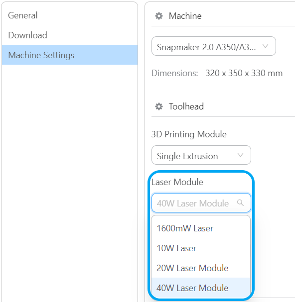
If you have already installed Luban, make sure to update it to at least V4.9.0, and select 20W/40W Laser Module in Settings > Machine Settings > Toolhead.
¶ 03 Assembly & Installation
To complete the assembly, you can either read the Assembly Guide in PDF format, or follow the online instructions below.
Before any assembly and installation, make sure the machine has been powered off.
¶ 3.1 Parts List
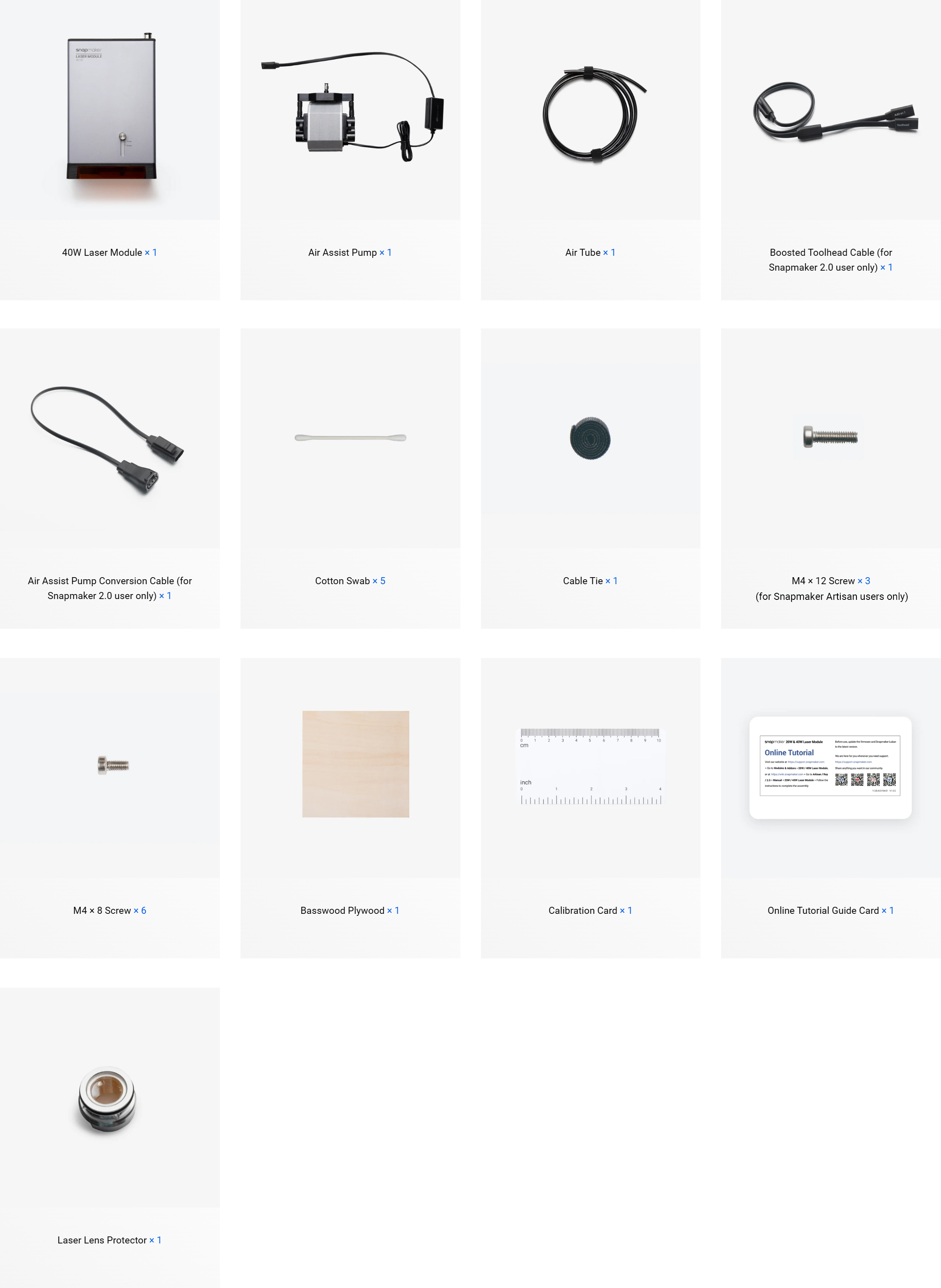
The spare laser lens protector included with the product is placed in the packaging, please keep it properly. It is used for maintenance, refer to Replacing the laser lens protector of the laser module for more detailed information.
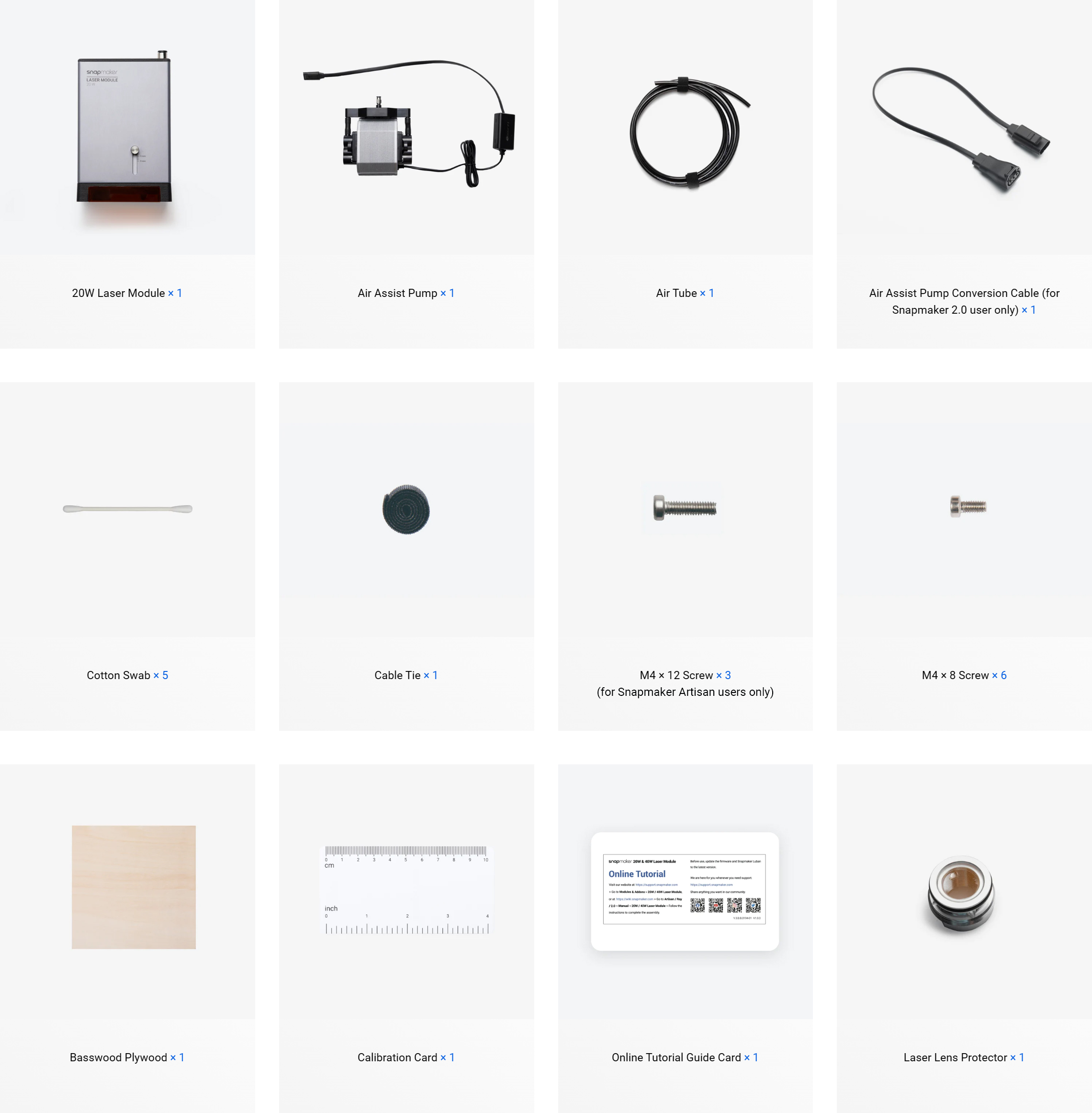
The spare laser lens protector included with the product is placed in the packaging, please keep it properly. It is used for maintenance, refer to Replacing the laser lens protector of the laser module for more detailed information.
¶ 3.2 Installing the toolhead
¶ 3.3 Installing the air assist pump
¶ 04 Setup
¶ 4.1 Restarting the machine
After updating the firmware and restarting the machine, the touchscreen will prompt a pop-up window to confirm the installation status of the quick swap kit.
There is a difference in the stroke of the Y axes and Z axis between the installation status with and without the quick swap kit, it is essential to select the appropriate installation status. Failure to do so may result in abnormal operation or damage to the product.
To restart your machine, wait for at least 5 seconds after power-off.
¶ 4.2 Calibrating the platform height
After reading the safety notes, tap Start, and the touchscreen will guide you through the Platform Height Calibration.
To recalibrate the platform height, swipe left on the touchscreen > select Settings > tap Guide.
¶ 4.3 Connecting the machine to Luban
You can connect the machine to Luban via a serial port or Wi-Fi and perform a series of operations.
File transfer to the machine is only supported via Wi-Fi.
When a task is started on Luban, it will be immediately stopped due to a serial-port disconnection.
Snapmaker 2.0 also supports LightBurn. For detailed tutorials, refer to Using Ray/Artisan/2.0 with LightBurn.
¶ 05 First Work
In order to help you quickly become familiar with the workflow for using the 20W/40W Laser Module with Luban and complete your first laser creation, this section will guide you through Luban's Beginner's Guide. You will have fun with the provided laser material and the example project tailored for your first creative experience.
¶ 5.1 Preparing the material
Take out the provided basswood plywood sheet from the material bundle, then fix the material on the platform using masking tapes.
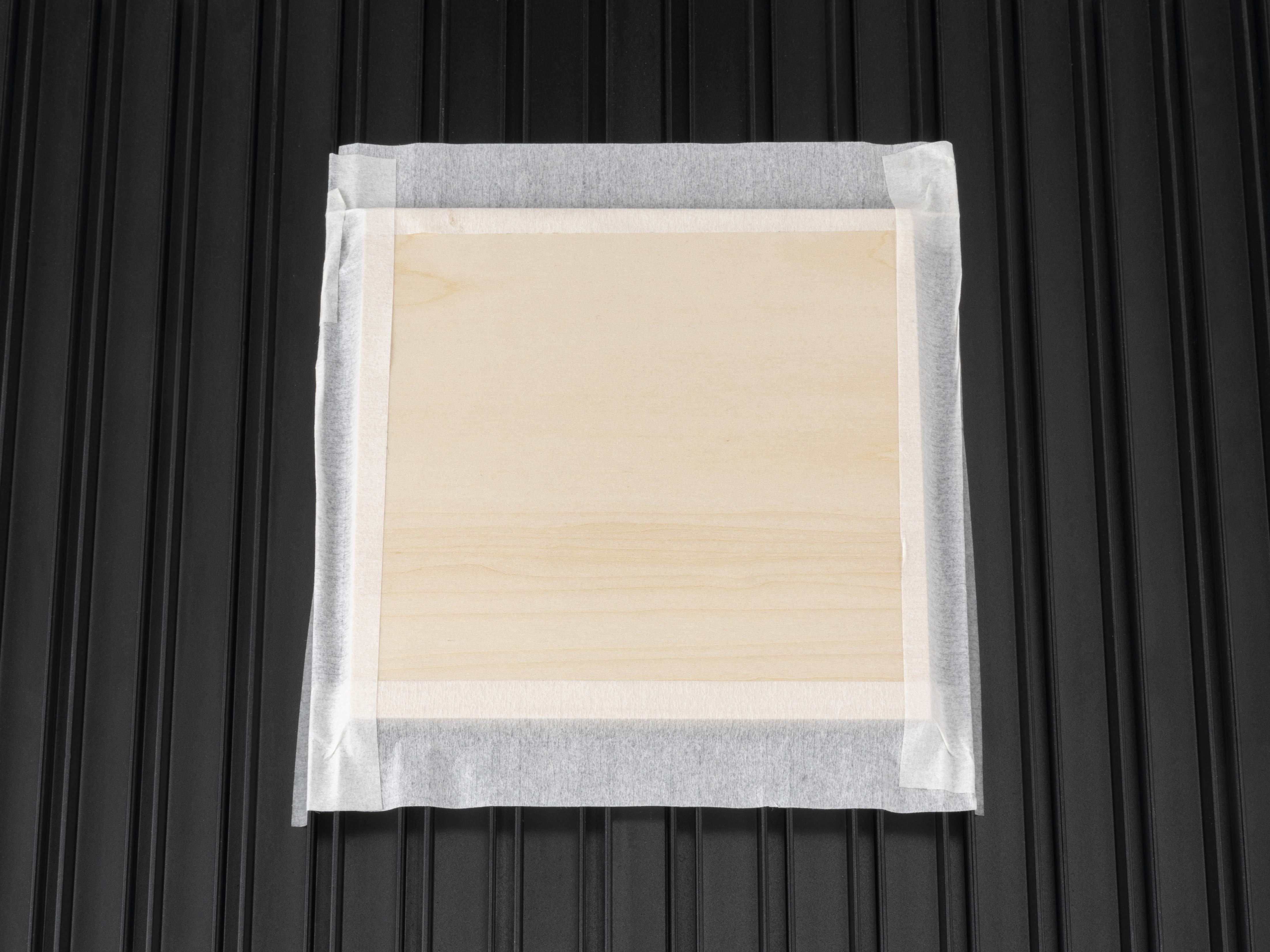
We do not recommend using fixtures that may collide with the laser safety shield of the 20W/40W laser module during the task to fix materials.
Do not use highly reflective materials (except for 304 stainless steel and anodized aluminium), as they can reflect blue light, which may cause burning on the bottom cover of the laser module, and increase the safety risk of burning nearby objects or even causing fires.
¶ 5.2 Preparing and transferring the G-code file
-
At the top-left corner of Workspace, click Back to return to the Home page of Luban. Then, select Laser > 3-axis to enter the Laser G-code Generator.
-
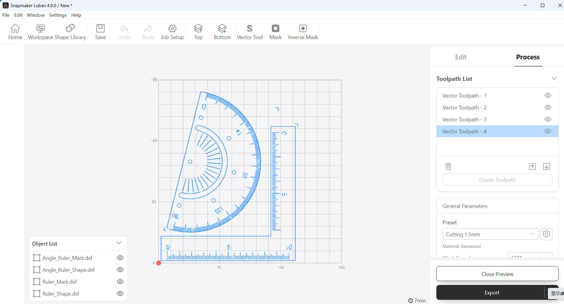
Familiarize yourself with the basic operations by following the Beginner's Guide. During this process, Luban will automatically load the example project and generate the G-code file.
If the Beginner's Guide does not pop up or unexpectedly closes, you can access it by clicking Help > Beginner's Guide in the menu bar.
You can also import your own files and configure the parameters.
-
After the G-code file is generated, click Export > Load G-code to Workspace at the bottom-right corner. The interface will automatically redirect to Workspace.
-
In the G-code Files panel, click Send to Device. The G-code file of the example project will be transferred to your machine.
Starting the laser task via Wi-Fi network is not supported due to safety concerns.
- After receiving the G-code file, tap Disconnect on the Touchscreen. Then find and select the received G-code file, and tap Next to enter the laser job preparation.
¶ 5.3 Adjusting the laser height
Adjusting the laser height to focus the laser can ensure optimal engraving and cutting outcomes.
¶ 5.4 Setting the XY work origin
Find out where the engraving/cutting will take place by setting the Work Origin. The Work Origin corresponds to the (0, 0) coordinate origin in the software.
The XY work origin for the example project should be set at the left-front corner of the material (workpiece).
Tap X-/X+/Y-/Y+ to move the laser's crosshair to where the Work Origin will be, and then tap Set Work Origin and Run Boundary to check if the work origin is proper. If not, reset the Work Origin and run boundary again.
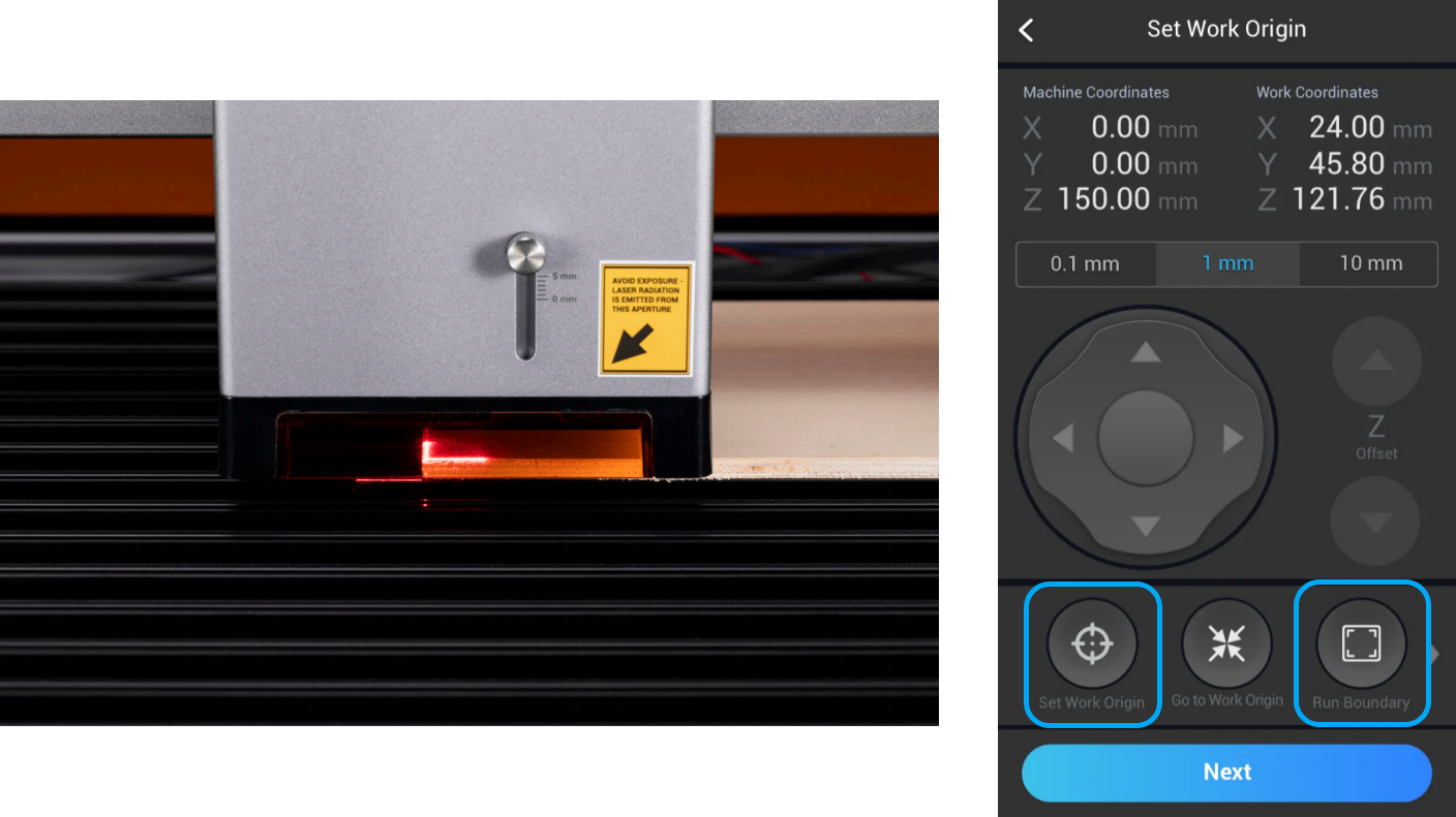
If the Laser Module runs into any portions of the machine, turn off the machine immediately.
¶ 5.5 Starting laser engraving and cutting
- IF you have installed the Enclosure, make sure the Enclosure door is closed and will stay closed throughout the task.
- Tap Start Job to start the laser task.
Keep the machine attended throughout the task!
¶ 06 Maintenance
To ensure the engraving and cutting effects, please perform the following maintenance operations.
- Cleaning the laser platform
- Cleaning the laser lens protector
- Replacing the laser lens protector
- Cleaning the bottom cover