Before you start, we recommend watching the U1 Video Guide, which can walk you through the initial setup and help you get ready with your first print.
¶ 1. Updating the Firmware
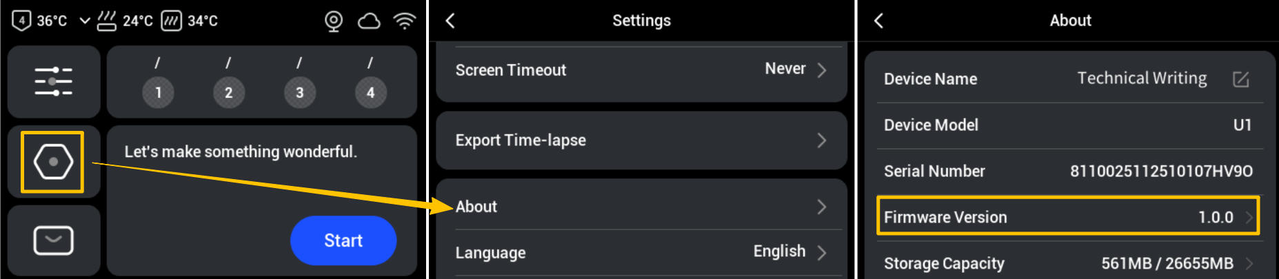
To ensure optimal performance, make sure the printer is running the latest firmware. Please refer to the U1 Firmware Release Notes for the latest version and follow the U1 Firmware Update Procedure for update instructions. Taking V1.0.0 as an example, you can check your current firmware version on the touchscreen settings menu:
¶ 2. Loading Filaments
2.1 Select the filaments you need and mount them on the filament spools.
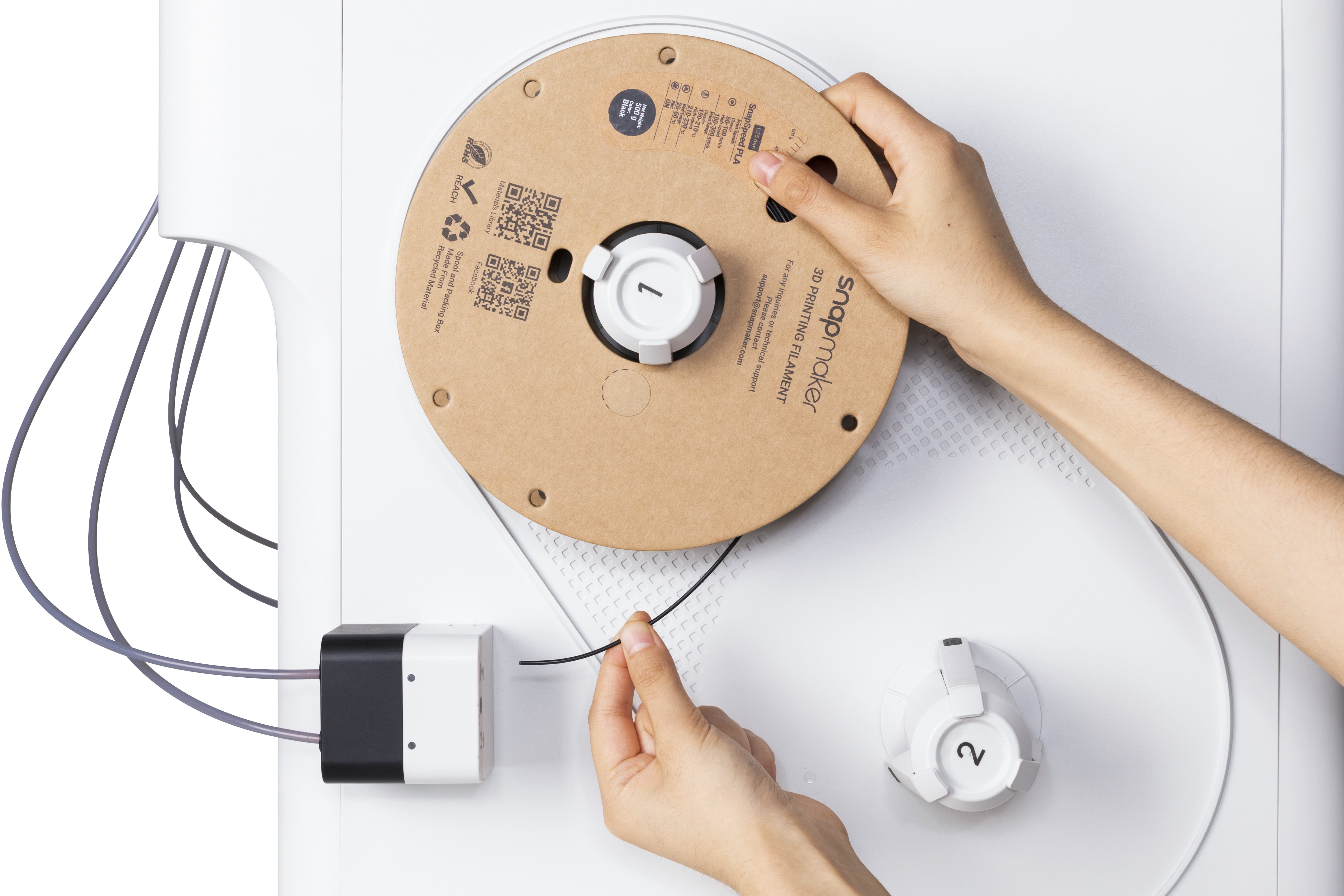
2.2 Load the filaments using either automatic loading or manual loading.
U1 offers two filament loading modes: automatic and manual.
When using rigid filaments or flexible filaments rated 95A or above, Automatic Loading is recommended.
When using flexible filaments rated below 95A, Manual Loading is required.
¶ 3. Running a Test Print
Once calibration is complete, print a four-color test model. Run your fingers over the surface and check for any noticeable ridges or unevenness to verify that the colors are properly aligned.
¶ 1. Importing the Model
¶ 1.1 Preparing Your Model File
The first step in 3D printing is to create a "digital blueprint" for your printer—the 3D model file. You can download models from popular 3D model sharing communities and resource platforms, or use 3D modeling software to design your own unique models.
¶ 1.2 Meeting Snapmaker Orca
Snapmaker Orca is a slicing software based on Orca and specifically customized for Snapmaker 3D printers. Click to view the Snapmaker Orca Release Notes and download the latest version.
When you launch Snapmaker Orca, you will see the following interface:
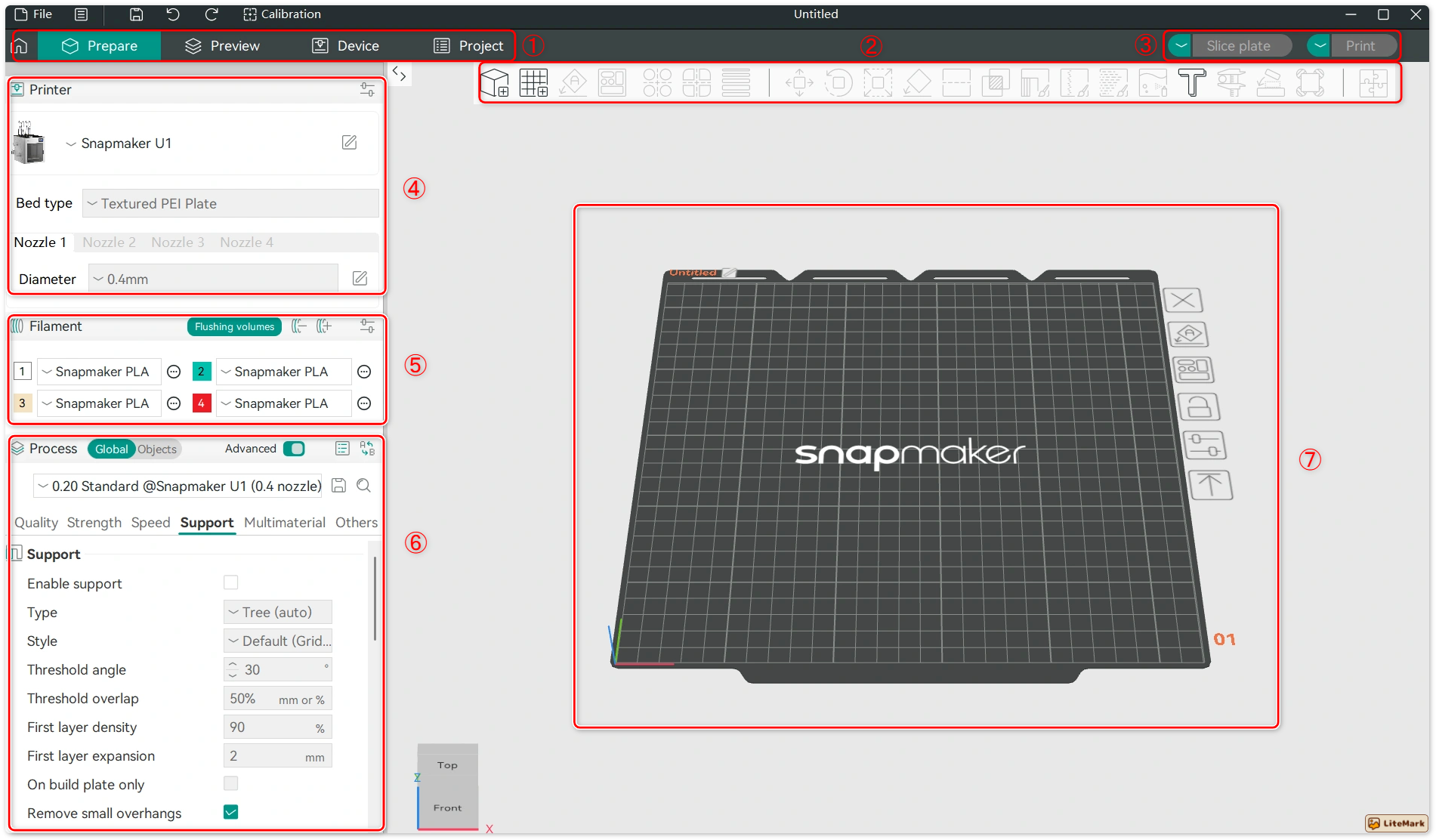
① Tab Bar: Includes Home, Prepare, Preview, Device, and Project.
② Toolbar: Provides tools for adding models, moving objects, painting, measuring, and more.
③ Action Bar: Used to slice models, generate G-code, and start print jobs.
④ Printer Settings: Allows you to configure the printer model and detailed parameters for each extruder.
⑤ Filament Settings: Allows you to add or remove different materials and manually configure their printing parameters.
⑥ Process Settings: Used to fine-tune model parameters to optimize print quality, speed, strength, and other performance aspects.
⑦ Model Display: The central area for viewing the 3D model, supporting rotation, panning, and zooming.
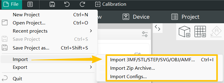
¶ 1.3 Importing a 3D Model
Next, import your model file into the slicer to begin the actual print setup. Snapmaker Orca currently supports the following two methods for importing models:
- Method 1: Drag and drop the model file directly into the software interface.
- Method 2: Click File > Import and select the corresponding file to import locally.
¶ 2. Basic Setup
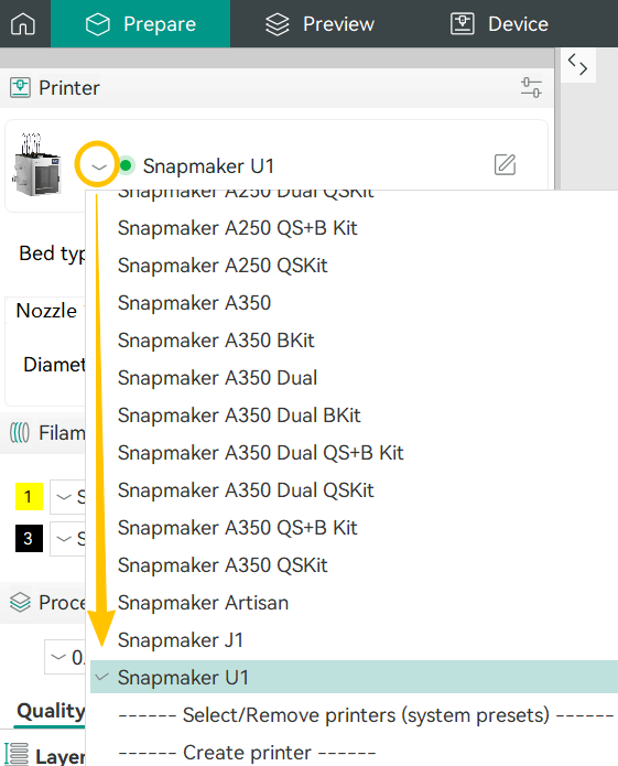
¶ 2.1 Selecting the Printer
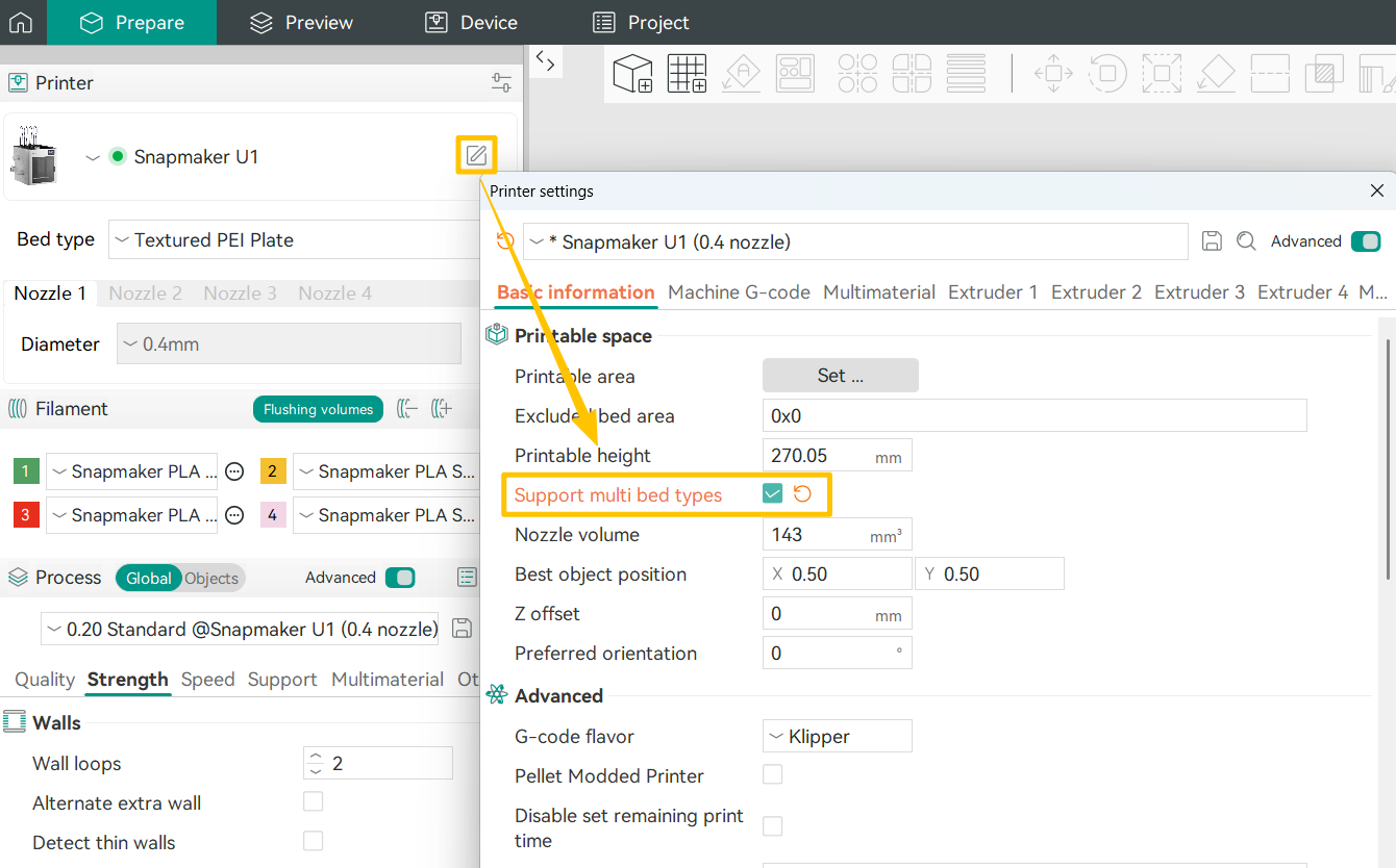
The default nozzle diameter for Snapmaker U1 is 0.4 mm, and the printer is paired with a textured PEI plate. To switch to a different model, click the icon and select the printer that matches your device.
¶ 2.2 Filament Mapping
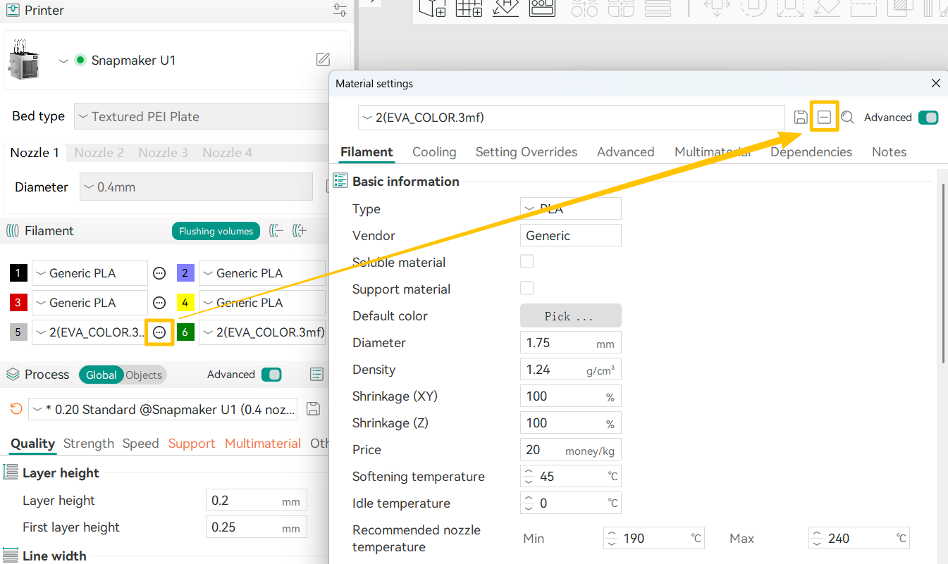
After importing the model, click the drop-down arrow next to the filament to view Machine Filament (the filaments currently loaded on the printer), Project Presets (the materials previously defined in the model), and System Presets (Snapmaker official filament profiles). Before starting a print, make sure the filament settings here match the filaments loaded on your printer. Otherwise, issues such as spaghetti or color contamination may occur.
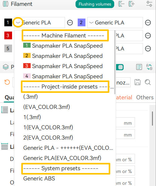
To remove a project preset, click the icon on the right > Edit > click the ➖ icon to delete the selected preset.
¶ 2.3 Painting Your Model
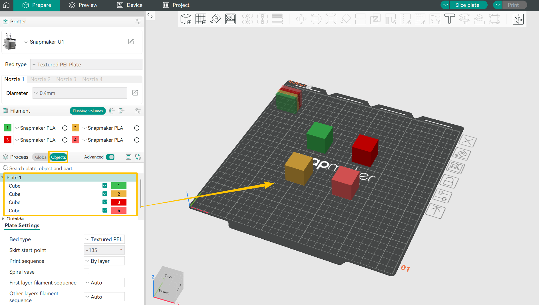
(1)Multiple Single-Color Models
Click Object in the Process Settings and assign a specific color to each object displayed on the right.
(2)Single Model with Multiple Colors
Snapmaker Orca provides six painting tools. In the following section, we’ll use a four-color baby dragon model as an example. You can also download the same dragon model from MakerWorld (@IK3Digital) to practice.
① Circle Tool
This versatile brush lets you paint directly onto your model’s surface. You can adjust the brush size to suit your needs.
Enable the Vertical or Horizontal option, and the tool will maintain a strict vertical or horizontal orientation while painting, making it easier to draw straight lines.

② Sphere Tool
Unlike the Circle tool, the Sphere tool colors every surface within the sphere, visible or not.
③ Triangle Tool
Use the Triangle tool to paint individual triangle faces under your cursor. A single click colors one triangle face, while dragging allows you to paint multiple connected triangles continuously.
④ Height Range
Use this tool to color surfaces based on Z-axis height. All surfaces within the specified height range will be uniformly colored, even if they are not physically connected in space.
⑤ Fill Tool
The Fill tool starts coloring from the face under your cursor and automatically spreads to all connected faces. The fill stops when it encounters faces of a different color. If Edge Detection is enabled, the fill will also stop when it reaches edges sharper than the specified threshold, preventing the color from spilling across distinct folds or corners.
If the fill covers too much (overflow) or too little (underfill), you can adjust the Smart Fill Angle for more precise control:
-Increase the value: The fill will cross gentler edges, expanding coverage—ideal for large, continuous areas.
-Decrease the value: The fill will stop at sharper edges, reducing coverage—perfect for fine details.
⑥ Gap Fill
Manual painting often leaves small gaps, which can affect the model’s appearance and increase material swaps. The Gap Fill tool automatically detects these empty areas and fills them using colors from neighboring faces.
To prevent Undesirable color blending, we recommend scaling up your model before printing. If you notice tiny gaps on the surface, use the Gap Fill tool and set the gap area to its maximum. The software will intelligently blend colors to improve the final result.
¶ 3. Initiating a Print
¶ 3.1 Binding Your Printer
Please refer to the Snapmaker Orca Quick Start Guide for U1 to complete printer setup and ensure that the Snapmaker Orca is successfully connected to your device.
¶ 3.2 Slice Preview
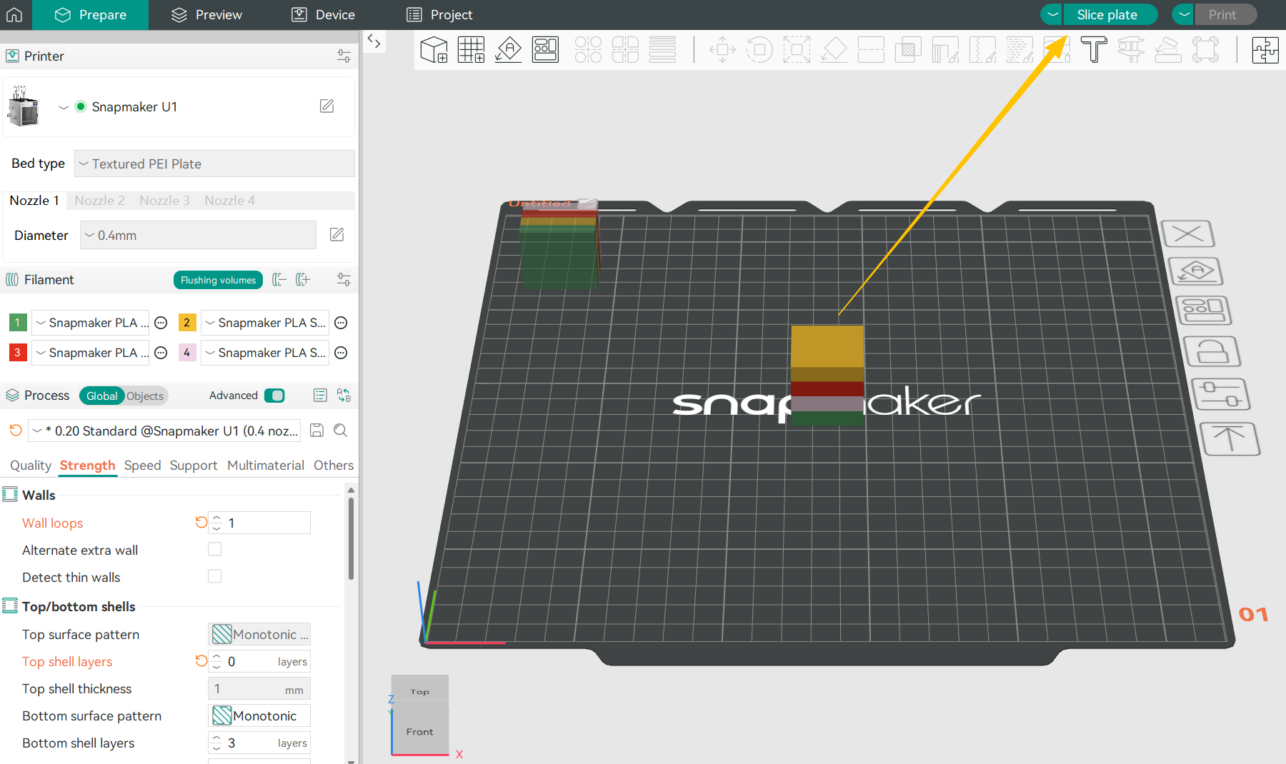
Return to the Prepare page and click Slice Plate. The interface will automatically switch to the Preview page.
¶ 3.3 Generating G-code
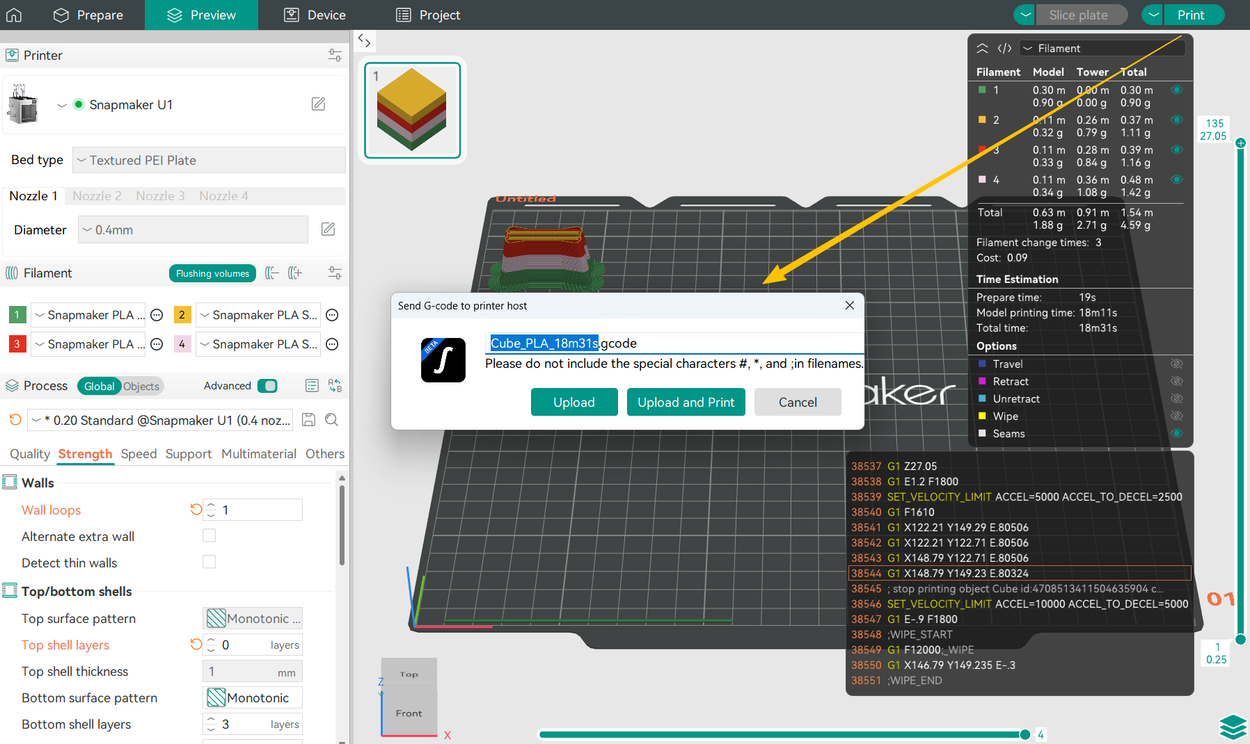
After double-checking that your model is correct, click Print. The software will automatically generate the G‑code file.
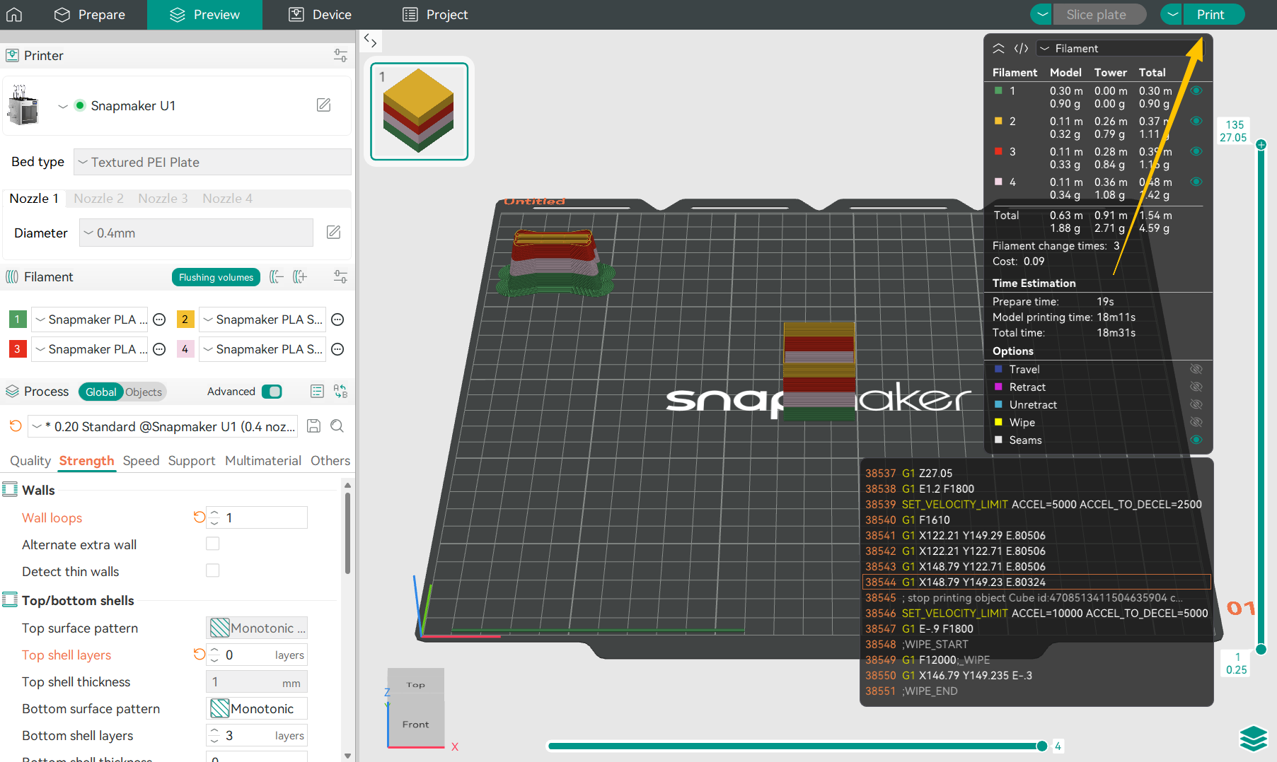
Click Upload and Print to enter the Print Preprocessing page.
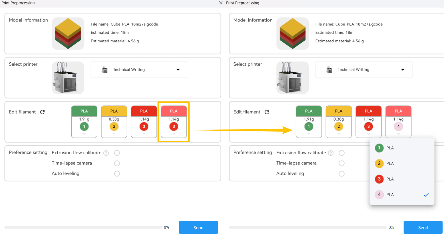
¶ 3.4 Print Preprocessing
Verify that the toolhead numbers assigned by the software match the loaded filament numbers. If colors are similar and the software misidentifies them, you can manually correct them.
For Preference Settings, we recommend adjusting based on your specific scenario:
- Extrusion Flow Calibration: Click this when:
- Installing or using the printer for the first time;
- Replacing or performing maintenance on the toolhead(s);
- Changing filament;
- Experiencing abnormal extrusion (over- or under-extrusion).
- Auto Leveling: Click this when:
- Installing or using the printer for the first time;
- Replacing the toolhead(s), heated bed, or nozzle(s);
- After a firmware update;
- After moving the machine or experiencing vibration;
- Observing frequent first-layer lifting or poor adhesion.
¶ 3.5 Sending the Print Job
Click Send, and the software will send the generated G‑code file to the printer and begin the print job.
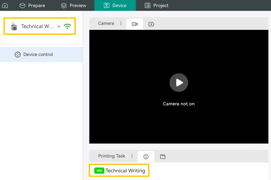
You can monitor the print remotely via the Snapmaker Orca or the Snapmaker App. Additionally, the Snapmaker U1 supports time-lapse photography. Click to learn how to export time-lapse files.
¶ 4. Print Complete
🎉Congratulations on completing your first multi-color print! Wait until the heated bed has cooled to room temperature before removing the model from the PEI sheet.
Regular cleaning of the PEI sheet helps maintain its adhesion and improves the success rate of future prints. We recommend using dish soap and a cloth for cleaning. Click How to clean your PEI plate for detailed instructions.
When you import a file, any parameters within the model are automatically loaded. Snapmaker Orca groups these settings into three preset categories: Printer, Filament, and Process. You can adjust the default values individually within each section.
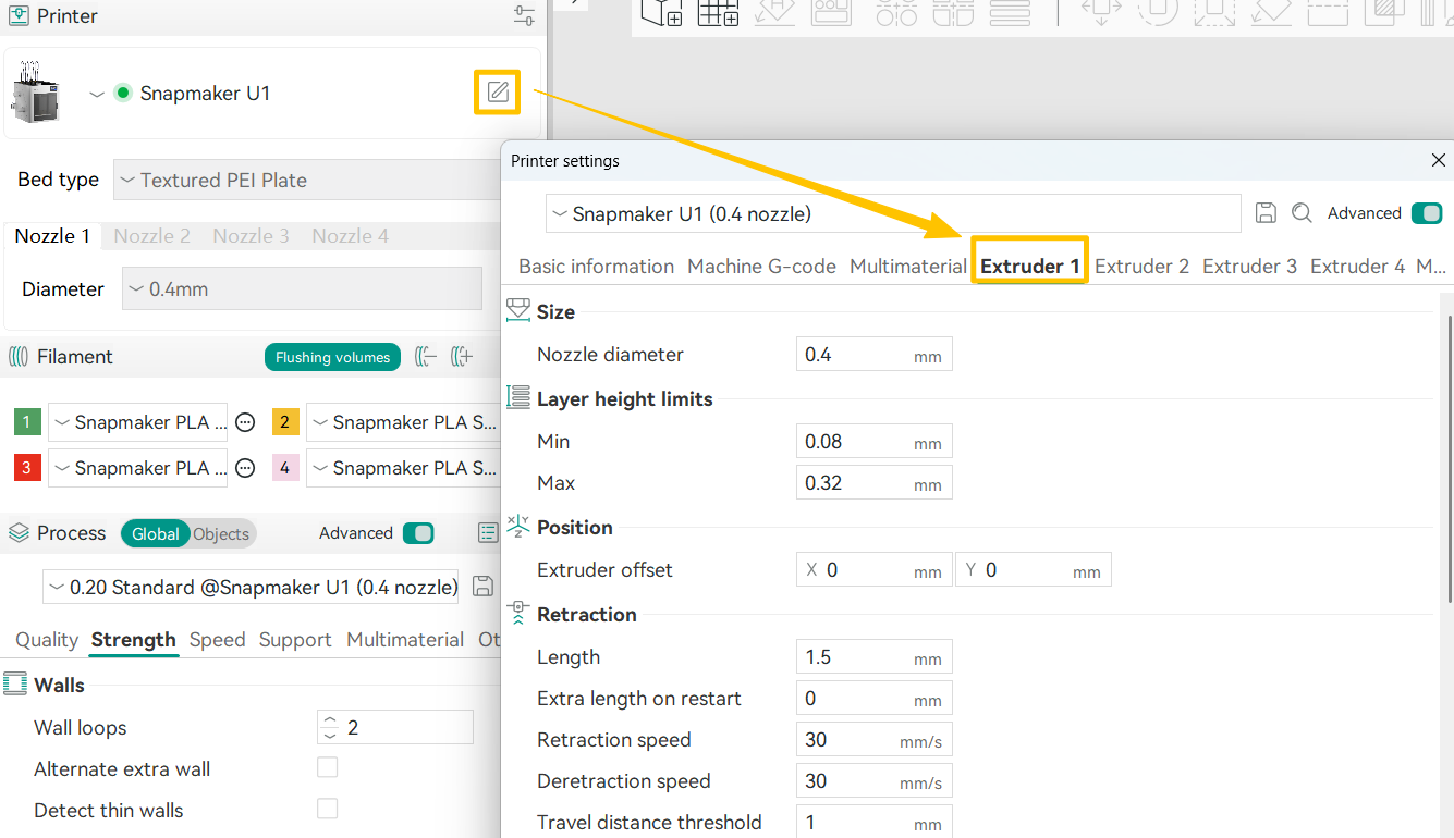
¶ 1. Printer Settings
Click the ✏ icon on the right to configure the printer model, heated bed type, or fine-tune settings for each extruder.
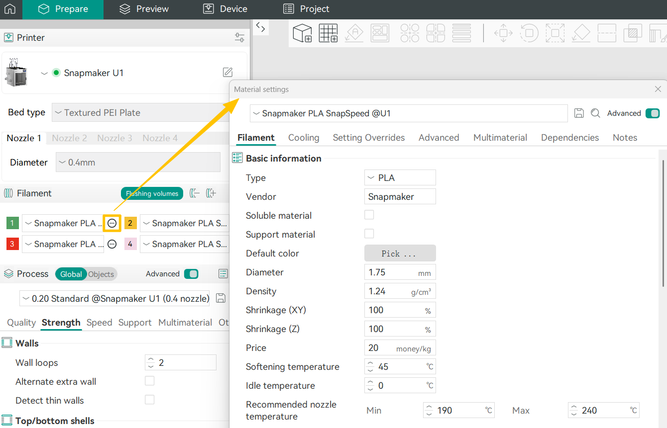
¶ 2. Filament Settings
To customize a specific filament, click the Edit button next to the material. Below are some commonly used parameters you may want to adjust:
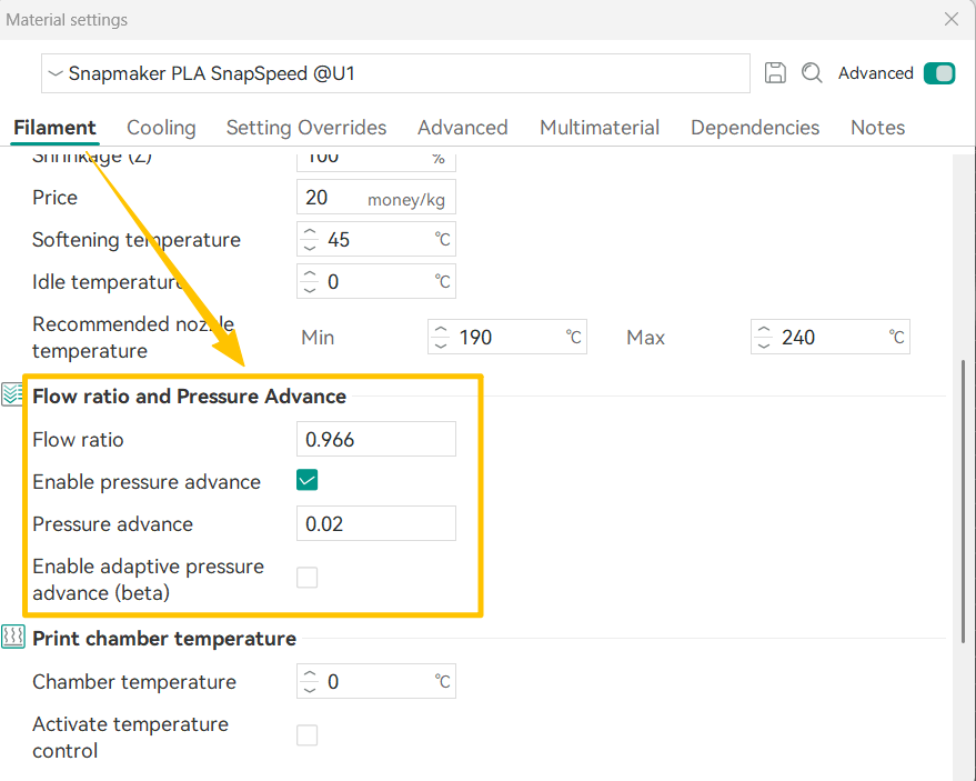
¶ 2.1 Flow Ratio and Pressure Advance
- Flow Ratio
As a material transitions between its molten and solid states, its volume may change. This setting scales all extrusion values for the selected material in the G-code. The recommended range is 0.95 to 1.05. If you notice slight over-extrusion or under-extrusion, adjusting this value can help achieve a smoother surface finish. - Enable Pressure Advance
This option compensates for pressure lag in the nozzle during acceleration and deceleration. It helps reduce issues such as oozing and blobs, improving overall print quality—especially around corners or during high-speed moves.
¶ 2.2 Print Temperature and Bed Temperature
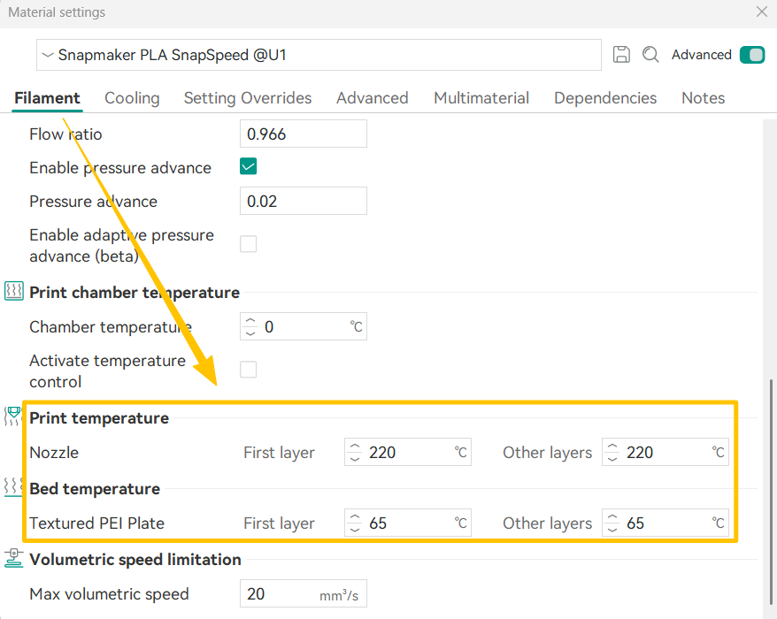
Different materials often require different nozzle and bed temperatures. You can refer to the table below to set the appropriate print temperature and bed temperature for each filament.
| Material | Nozzle Temp (°C) | Bed Temp (°C) for Textured PEI Plate |
|---|---|---|
| PLA | 190-230 | 55-65 |
| PETG | 230-270 | 60-80 |
| TPU | 220-240 | 30-35 |
| PVA | 210-250 | 55-65 |
| PCTG | 240-280 | 65-85 |
| PET | 260-290 | 80-100 |
| ABS | 240-280 | 90-100 |
| ASA | 240-280 | 90-100 |
| PA (Nylon) | 260-300 | 60-100 |
| PC | 260-300 | 80-100 |
| PLA CF | 210-240 | 55-65 |
| PETG CF | 240-270 | 60-80 |
| PET CF | 260-300 | 70-100 |
| ABS GF | 240-280 | 90-100 |
| ASA CF | 250-290 | 90-100 |
| PA6 CF | 260-300 | 60-100 |
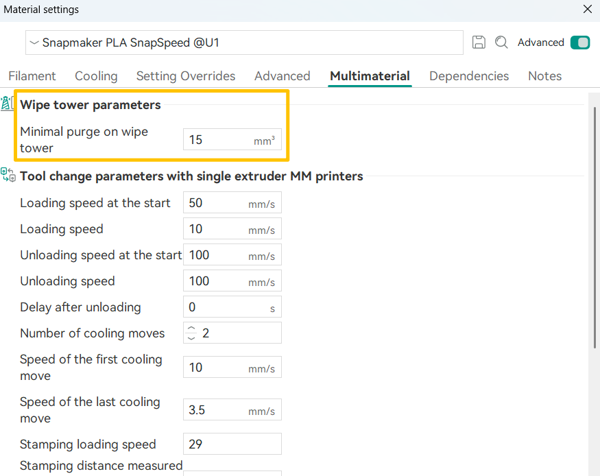
¶ 2.3 Wipe Tower Parameters
- Minimal Purge on Wipe Tower
This specifies the amount of filament purged during the first tool change of each layer. The default value is 15 mm³.
¶ 3. Process Settings
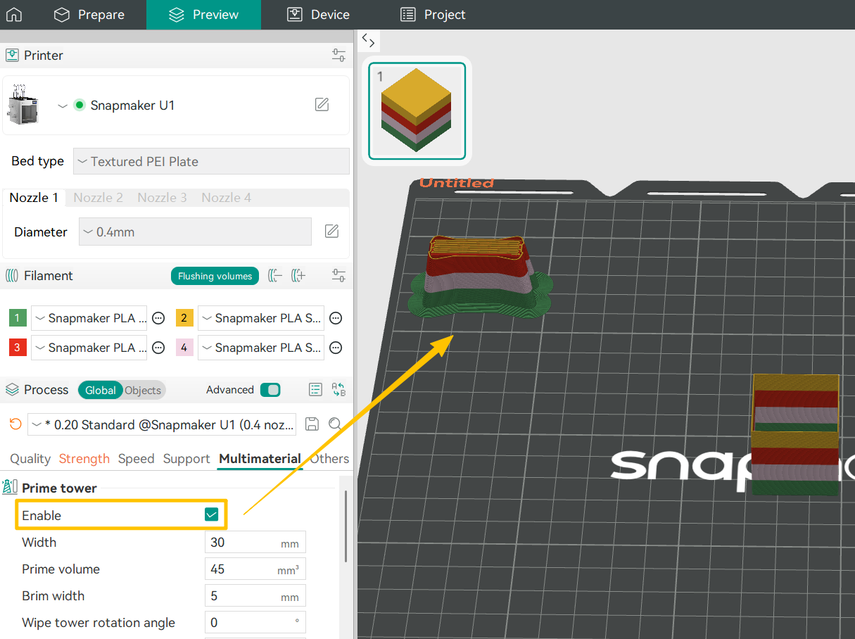
¶ 3.1 Prime Tower
(1)Why do you need a prime tower for multi-color printing?
The prime tower is designed to stabilize extrusion after a color change. To enable fast tool changes in multi-color printing, inactive toolheads are kept at a standby temperature and preheated in advance. However, when filament remains at high temperature for extended periods, its material properties can degrade. As a result, extrusion may be unstable when printing resumes, leading to issues such as stringing, dripping, or inconsistent color output.
(2)How do you configure prime tower settings?
The default prime tower settings are suitable for most printing scenarios. If you want to fine-tune them based on your model and filament properties, we recommend adjusting the following parameters:
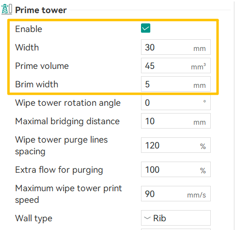
- Width
The default prime tower width is 30 mm. This value is chosen to produce a near-square cross section when paired with a 45 mm purge length. In the current version, if you need more precise control over the tower’s shape, you can fine-tune the width using this principle as a reference. - Purge Volume
The typical adjustment range is 40–60 mm³. For simple models with large color regions, you can reduce the purge volume to save material. For models with fine details or frequent color transitions, increasing the purge volume helps ensure clean color changes. - Brim Width
For most models, a brim width of 3–8 mm is sufficient. Taller prime towers may require 10 mm or more. If the prime tower is particularly tall or you are using filaments prone to warping (such as PETG or ABS), set the prime tower brim width to 1.5–2× the brim width of the model.
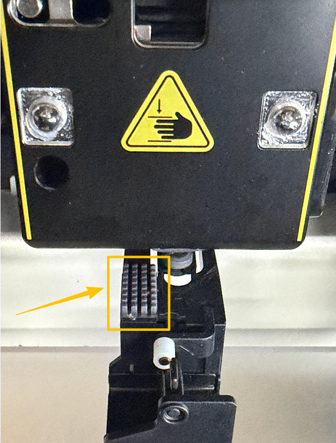
To further reduce the risk of color contamination, regularly clean the nozzle and the black silicone wiper beneath the toolhead using the wire brush in your tool box.
(3)How do you configure color-change settings for each filament?
To reduce reliance on large purge volumes in the wipe tower, you can use multi-tool ramming together with wipe tower settings to achieve cleaner and more efficient multi-color prints.
To access these settings, click the button next to the target filament, then go to Edit > Multimaterial, and scroll down to the corresponding section.
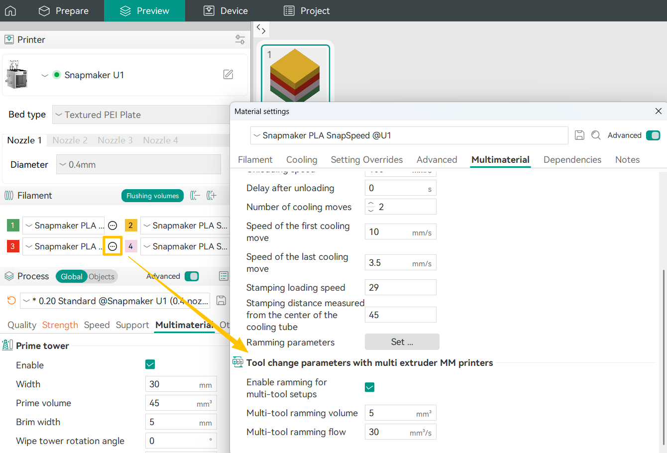
- Multi-tool Ramming Volume
This defines the minimum amount of filament extruded after a tool change to restore stable extrusion. Based on internal testing, a value of 5mm³ works well with official PLA filament, effectively preventing color contamination while minimizing material waste. When using other materials, you can fine-tune this value following the same principle. - Multi-tool Flow
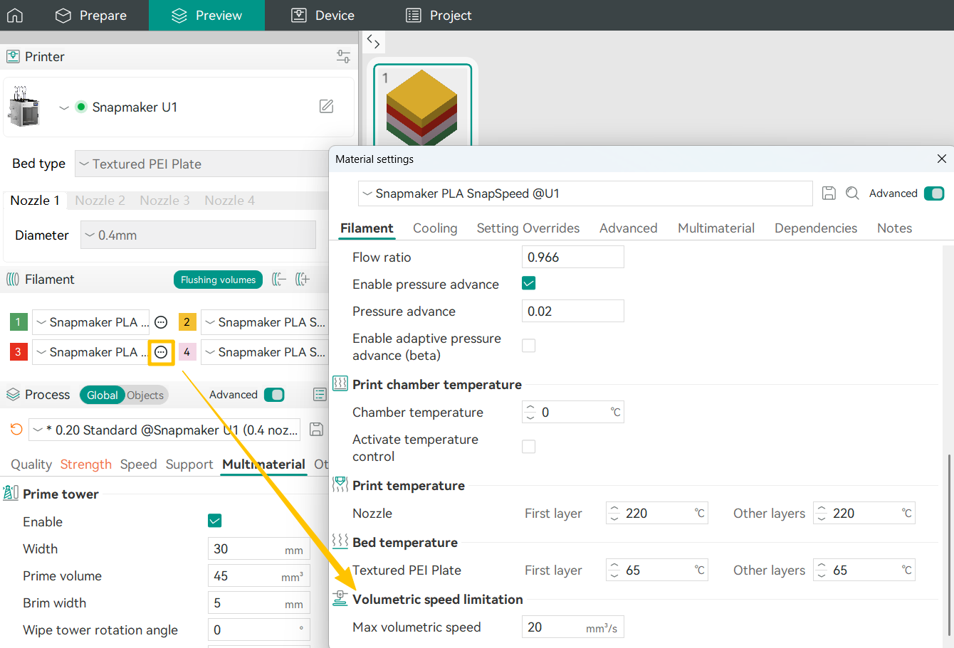
This controls the extrusion speed during the ramming process. In most cases, we recommend setting this to 1.2–1.5× the max volumetric speed.
¶ 3.2 Support
(1)Support Types
- Normal (auto)
This is the most basic support type. You only need to set an threshold angle, and the software will automatically generate dense, vertical supports beneath all areas that exceed this angle. It works like a reliable safety net, but the trade-off is that post-processing can be more time-consuming. - Tree (auto)
The software analyzes the model and generates branching, tree-like supports that grow and split to reach multiple overhangs while using minimal material. This approach significantly reduces material usage and makes supports easier to remove, making it especially well suited for statues, figurines, and other complex organic shapes. - Normal (manual)
In this mode, you can place individual support columns by clicking directly on specific areas of the model, much like using a brush tool. It is commonly used to supplement automatic supports that miss small, isolated overhangs; remove unwanted supports from critical surfaces (such as a figurine’s face); or reinforce key load-bearing areas by increasing support density or diameter. - Tree (manual)
This mode gives you full control over both the start and end points of supports, as well as their growth paths and branching structure. As the most advanced option, it requires a solid understanding of the model’s geometry and support principles to use effectively.
| Support Type | Core Principle | Key Advantages | Key Drawbacks | Typical Use Cases |
|---|---|---|---|---|
| Normal (auto) | The software generates dense vertical grid or line supports between the model and the build plate based on a predefined overhang angle. | Highly stable and reliable support generation. | High material consumption, difficult to remove, and likely to leave noticeable marks on the model surface. | Large models or structures with wide flat overhangs. |
| Tree (auto) | The software algorithm generates branching, tree-like structures that use minimal contact points to support multiple overhang areas. | Material-efficient, easy to remove, and fewer contact points. | Slightly less stable than normal supports; not suitable for supporting very heavy flat surfaces. | Figurines, characters, and models with complex curved surfaces and multiple isolated overhangs. |
| Normal (manual) | Users manually place vertical support columns (cylindrical or rectangular) at specific locations on the model. | Precise control; allows reinforcement of critical areas or avoidance of marks on important surfaces. | Highly experience-dependent and time-consuming to configure. | Refining automatic supports, fixing missed small overhangs, or protecting visually critical surfaces. |
| Tree (manual) | Users manually define the start points, paths, and branching of supports, which the software generates as customized tree-like structures. | Combines the efficiency of tree supports with the flexibility of full manual control, enabling highly customized support layouts. | Complex to operate; requires strong spatial understanding and experience. | Extremely complex geometries or fine-tuning the layout of automatic tree supports. |
(2)Styles
① Normal supports include two styles:
- Grid
The default style for normal supports. The support area is expanded into a regular grid pattern, creating a more stable and robust support structure. - Snug
The support area is not expanded and closely follows the shape of the overhang. This helps reduce material usage and minimizes surface marks on the model.
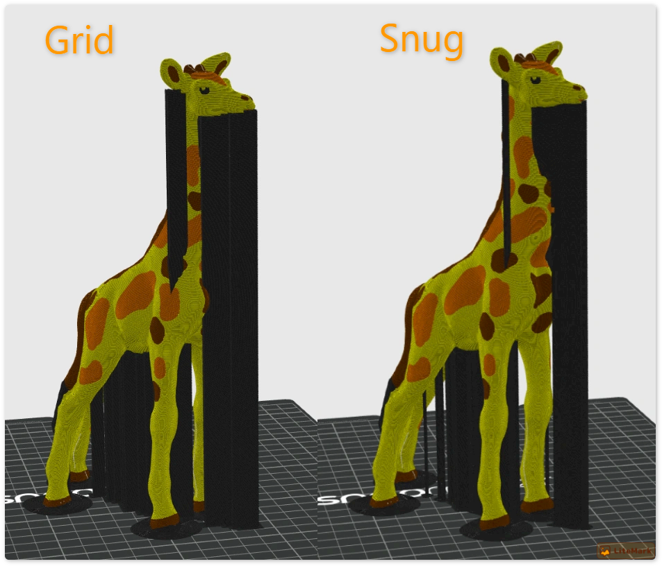
Normal supports are best suited for models with large flat overhangs, simple geometry, and relatively heavy structures.
② Tree supports offer four different styles:
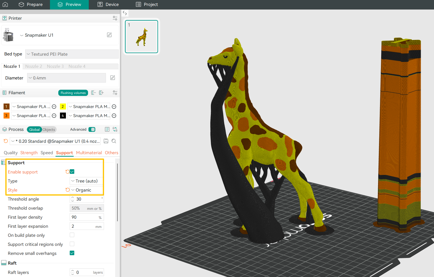
- Organic
Generated using a bio-inspired algorithm, this style finds optimized paths to reach overhang points. As the default tree support style, it balances material efficiency with easy removal.
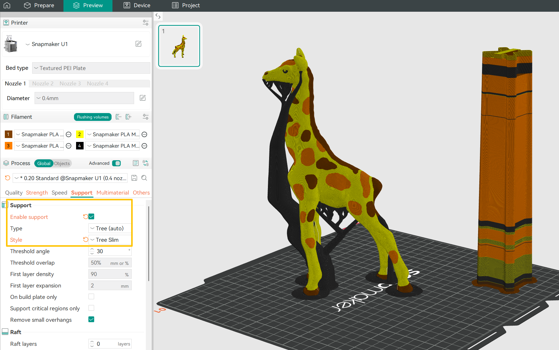
- Tree Slim
Uses more refined branch-merging logic to create smaller, lighter supports. This style minimizes material usage and removal marks, but provides lower structural strength.
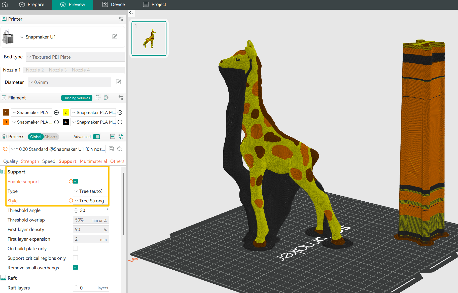
- Tree Strong
Features thicker and more stable branches with higher load-bearing capacity, offering additional support for larger overhangs. However, it may be more difficult to remove.
- Tree Hybrid
Combines the characteristics of tree supports and normal supports under large flat overhangs, allowing different support strategies to be optimized for different parts of the model.
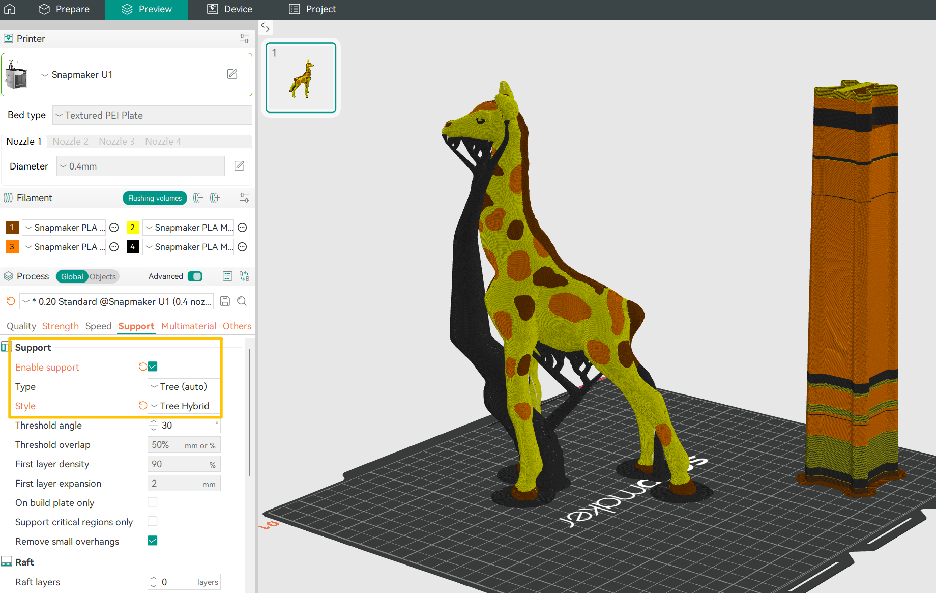
Tree supports are ideal for models with complex curved surfaces, fine details (such as figurines and statues), or multiple isolated overhangs.
(3)Manually Painting Supports
① On the Prepare page > click Support > Enable Support, and select either Tree (manual) or Normal (manual) as the support type.
② Select the model and click the Support Painting tool in the top toolbar.
③ Before you start painting, you can enable On Overhangs Only to help identify unsupported areas. Set an overhang angle, and the software will automatically highlight all faces below that angle.
④ Choose a painting tool and adjust the pen size or smart fill angle as needed.
- Hold the left mouse button and paint over the model surface to force supports in the highlighted (green) areas.
- Hold Shift + right mouse button and paint to remove supports you do not want.
(4)Threshold Angle
The threshold angle defines the maximum overhang angle that triggers automatic support. When a surface exceeds this angle, the software will generate support for that area. In general, the steeper the overhang, the larger the support area required. The default threshold angle is set to 30°. For most materials, this angle can be printed reliably without additional support.
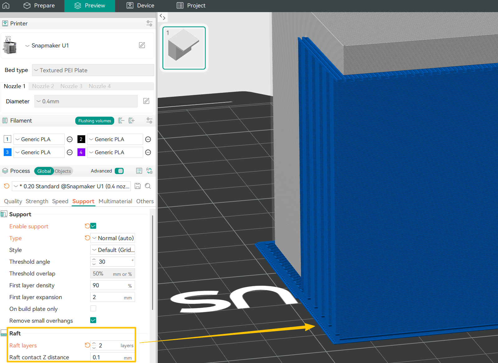
(5)Raft
① A raft is an additional grid-like base layer printed beneath the model to improve adhesion to the build plate. You can think of it as a dedicated “printing base” that helps address issues such as an uneven build plate, minimal contact area, or materials prone to warping.
We recommend enabling a raft in the following situations:
-The build plate is uneven or difficult to level.
-Printing materials that are prone to warping, such as ABS.
-The model has very small or point-contact bases, resulting in poor adhesion.
-The bottom geometry of the model is complex and does not adhere well when printed directly on the build plate.
② Increasing the number of raft layers makes the raft thicker and more rigid, but also increases material usage and print time. In most cases, 2–3 layers provide sufficient strength while remaining easy to remove.
③ Raft Z distance refers to the vertical gap between the top of the raft and the first layer of the model. A small gap makes the model easier to separate from the raft after printing. The default value is 0.1 mm. If this distance is set to 0 and the model and raft use the same material, they will bond firmly and may be difficult to separate.
During multi-color printing, you may encounter some issues. No need to worry. Here we’ve compiled common scenarios and solutions to help you quickly identify and resolve them.
¶ Issue 1: Different color regions are not properly aligned, causing overlapping or gaps.
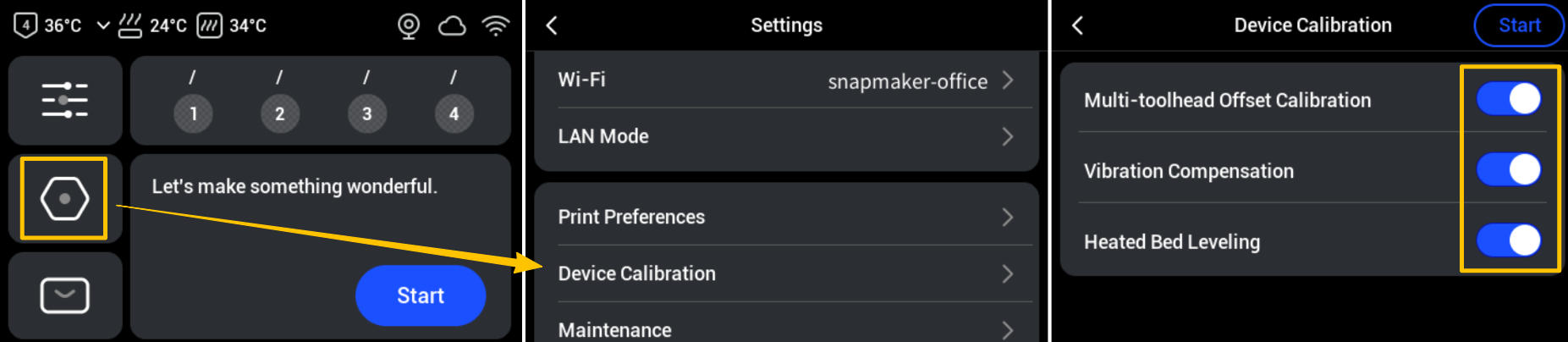
Possible Cause: The device is not calibrated, resulting in the XY positions of the four print heads being slightly off.
Solution: On the touchscreen main interface, go to Settings > Device Calibration and enable the relevant calibration options. Follow the on-screen instructions to complete the calibration process step by step.
¶ Issue 2: The print color does not match expectations.
Possible Cause: The filament colors are not correctly mapped to the toolheads.
Solution: Check the color assignment for each filament and toolhead.
- When printing from Snapmaker Orca:
On the Print Preprocessing page, verify that toolheads assigned by the software match the actual loaded filaments. If similar colors cause a misassignment (for example, the pink filament on toolhead 4 below), use the dropdown menu to manually correct the mapping.
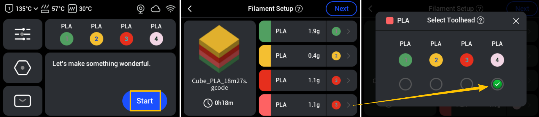
- When printing directly from the local device:
On the touchscreen, check and adjust the filament mapping. From the home screen, tap Start and select your local print file. Ensure the device’s assigned toolheads correspond to the actual loaded filaments. If similar colors cause a misassignment (such as the pink filament on toolhead 4), tap the arrow on the right to manually correct it.
¶ Issue 3: Color bleed-through on the model surface.
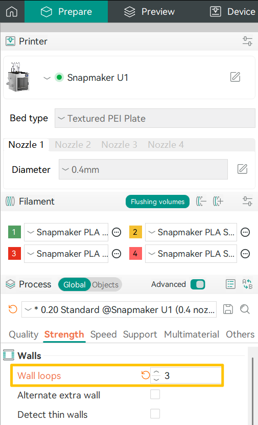
Possible Cause:Significant contrast between the infill color and the outer wall color (e.g., dark infill with a light exterior) or an insufficient number of wall layers.
Solution:When painting your model, try to avoid light exteriors over dark infills. You can also increase the number of wall layers (3 or more) to improve coverage.
If you encounter any other issues, please submit a ticket and we will provide help as soon as possible.