After selecting proper processing mode for the laser job, you can then create toolpath for it.
Toolpath settings are a crucial aspect of laser cutting and engraving in Luban. These settings determine how the laser will move and interact with the material, ultimately affecting the quality, precision, and efficiency of your project.
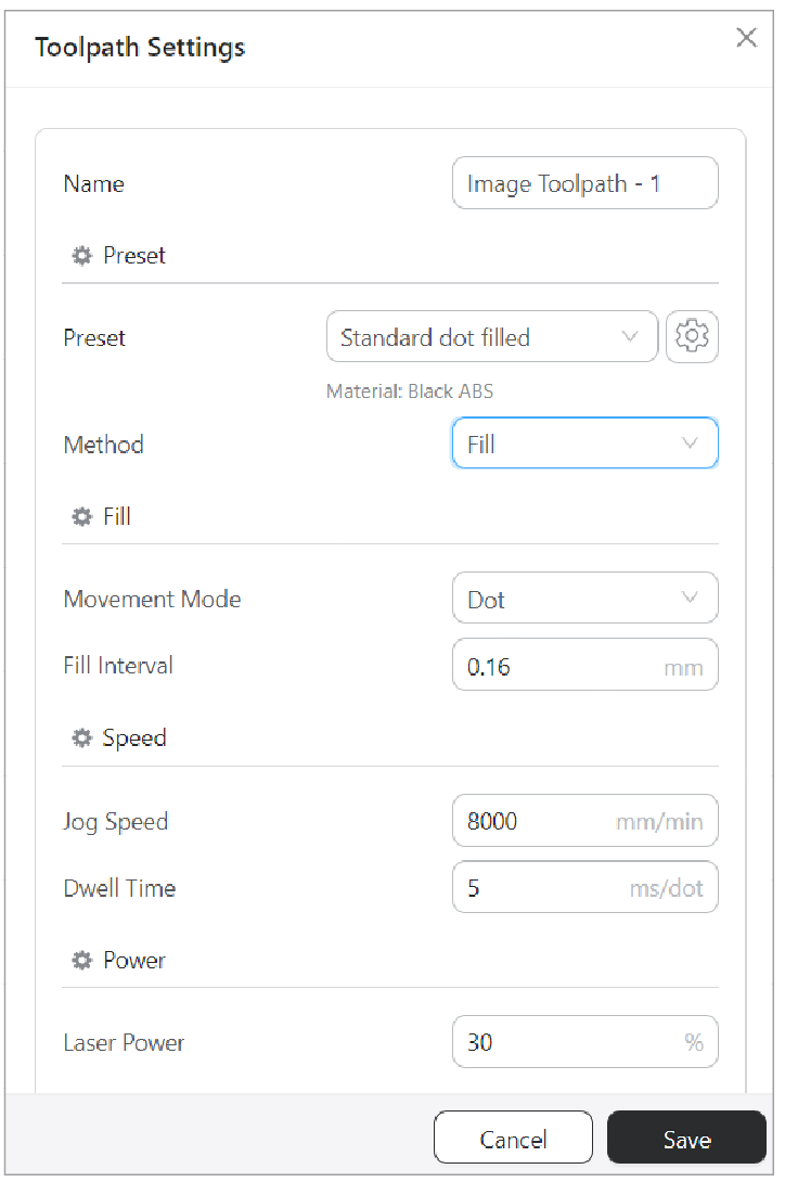
You can adjust the toolpath settings in Luban to suit different materials and effect, refer to - Adjust toolpath parameter settings. In addition, you can also create material or preset profile to customize the toolpath parameters, refer to - Create material or preset profile.
Laser processing modes and toolpath settings together determine the laser outcome: The processing modes define how the images will be processed, refer to - Laser: Four Processing Modes, while the toolpath settings control the specific movement of the laser.
Here comes the detailed explanation for each parameters:
¶ Name
Enter the toolpath name.
¶ Preset
¶ Preset
You can directly select one of the Luban's preset method for laser processing to process the object.
Or you can modify the parameters based on your own needs. The explanation of the parameters are listed below.
¶ Method
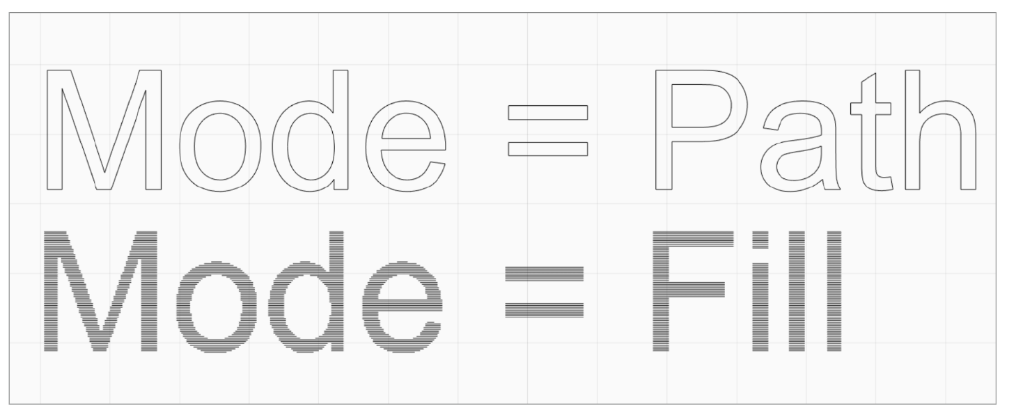
You can choose between two methods: On the Path and Fill.
¶ On the Path
Engraves along the shape of the object.
¶ Fill
Fills the object with lines or dots.
When you select Fill as Method, two other parameters will pop up: Movement Mode and Fill Interval.
¶ Fill
¶ Movement Mode
Movement Mode include Dot, Line and Variable Line.
¶ Line
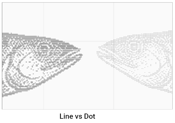
The object is filled with lines.
Though filling with lines will be faster, the engraving effect will not be as good as dot filling.
¶ Dot
The object is filled with dots.
Filling with dots has the best engraving result, but it will take a longer time.
¶ Variable Line
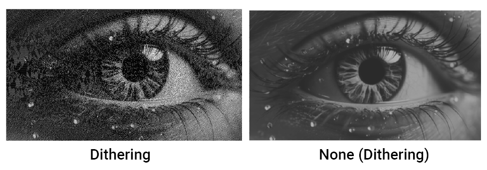
When you choose Variable Line for Movement Mode and choose None for Laser Processing mode Algorithm, you can activate None Dithering effect. More detailed explanation can be found in - Enable None Dithering.
¶ Fill Interval
Set the degree to which an area is filled with laser lines or dots.
The minimal interval is 0.01 mm (since V4.10.2).
In the Line-filled Engraving mode, the Fill Interval defines the distance between the lines comprising the engraved pattern. If the Fill Interval is too large, the engraved pattern will be light-colored or even discontinuous; if too small, the lines will overlap, making the pattern too dark or blurred.
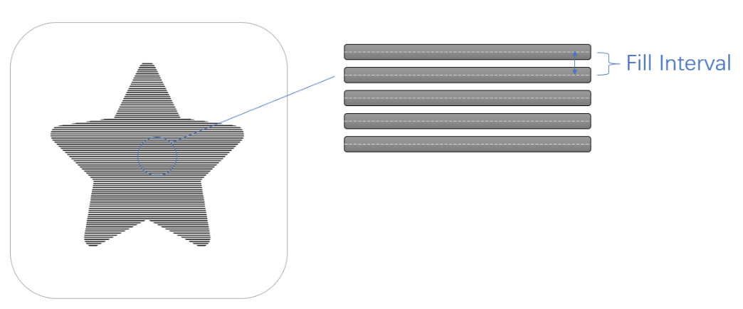
In the Dot-filled Engraving mode, which follows the similar principle as the Line-filled Engraving mode, the Fill Interval is the distance between the dots constituting the engraved pattern. If the Fill Interval is too large, the engraved pattern will be light-colored and might lose some details; if too small, the dots will overlap, making the engraving color too dark and the pattern indiscernible.
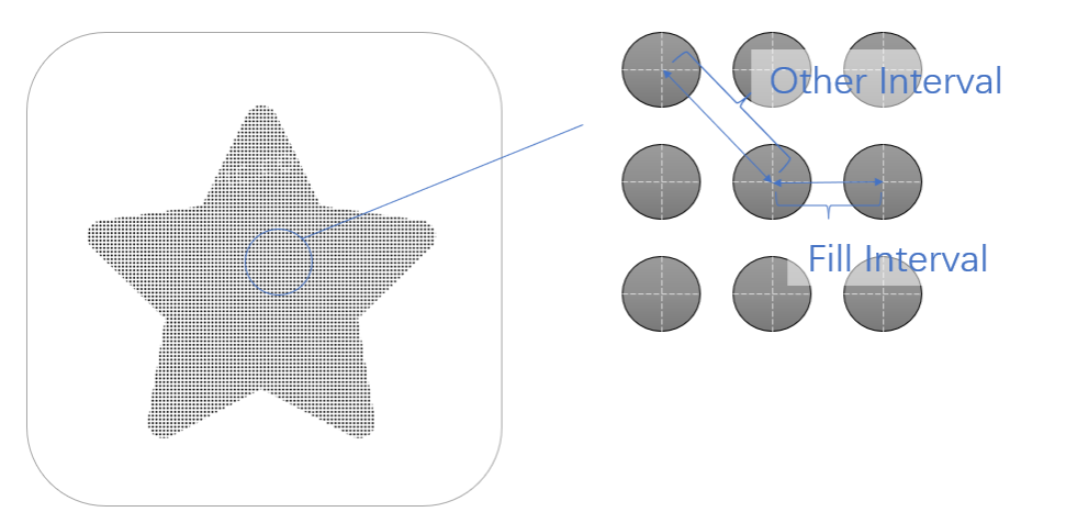
This is how the two modes differ: When you set the Fill Interval in the Line-filled Engraving mode, you only need to focus on the interval between each line and its adjacent line, but in the Dot-filled Engraving mode, you need to consider the interval between a dot and all of its surrounding dots. Therefore, the Fill Interval configuration in the Dot-filled Engraving mode is more complex.
¶ Line Direction
Appears only when the Movement Mode is set as Line.
Engraves the path in the horizontal, vertical, or diagonal direction.

¶ Speed
In high-speed fill operations, setting Jog Speed equal to Work Speed can enhance quality, since it reduces acceleration and deceleration, thereby suppressing vibrations and decreasing the impact of speed differences on laser engraving outcomes.
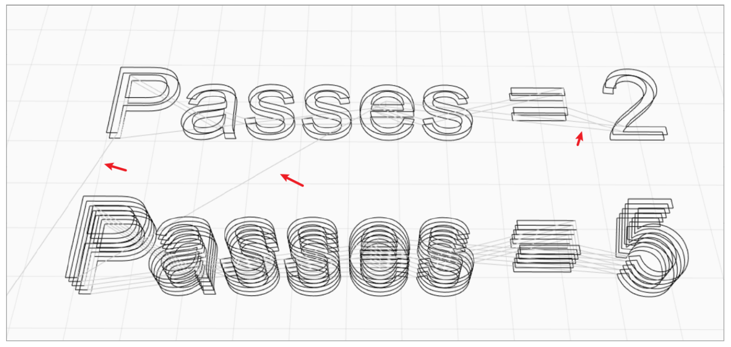
¶ Jog Speed
Set the speed at which the toolhead moves when it is not engraving or cutting. For example, when it travels along the grey lines in the figure below.
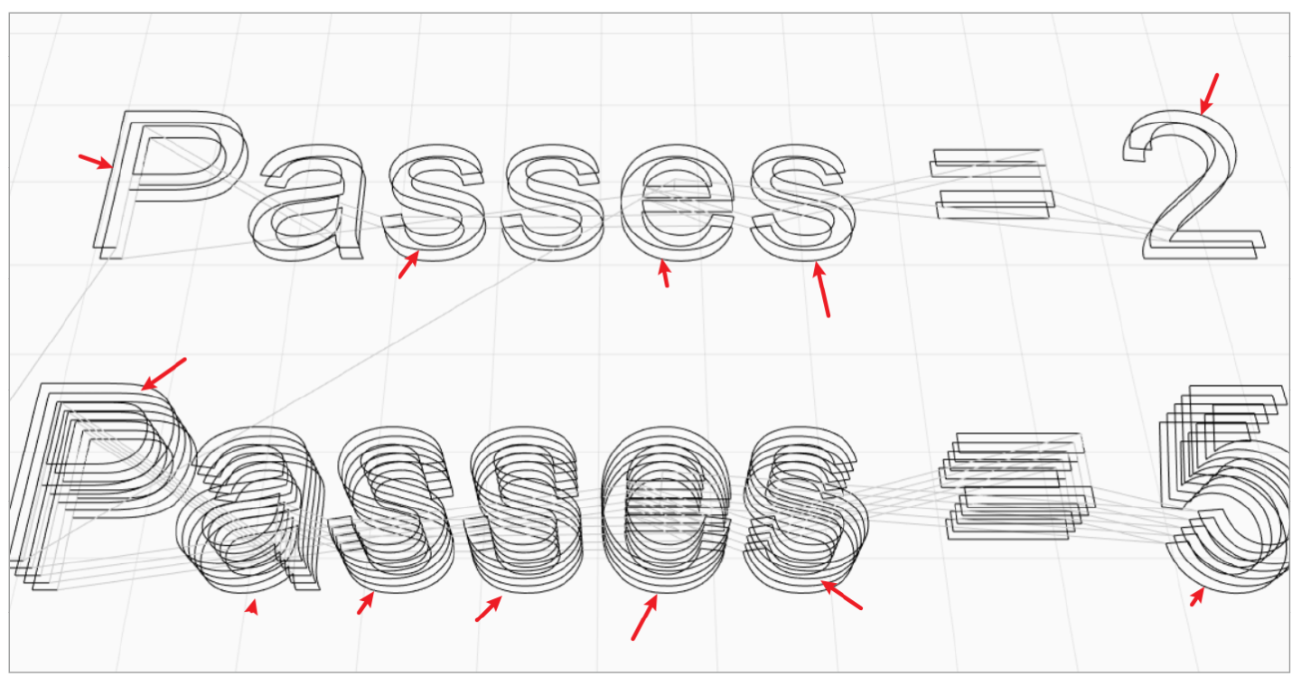
¶ Work Speed
Set the speed at which the toolhead moves on the material when it is engraving or cutting. For example, the speed when processing the black lines in the figure below.
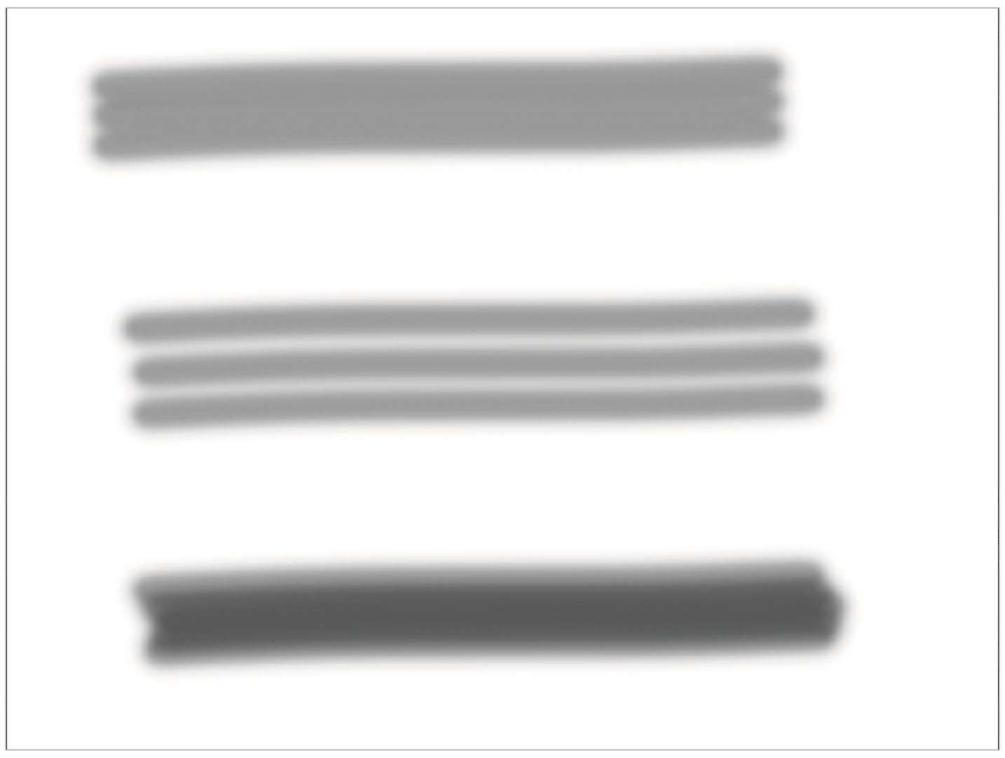
When Laser Power is set to a fixed value, the faster the toolhead moves, the shorter time the laser beam stays on the workpiece, and the less laser energy the workpiece absorbs. Therefore, in laser engraving, when the other parameters remain unchanged, the higher the Work Speed, the lighter the engraving color. In laser cutting, the higher the Work Speed, the shallower the laser cuts, and the less charred the cut edges.
¶ Dwell Time
Set how long the laser spot stays on when it is engraving a dot.
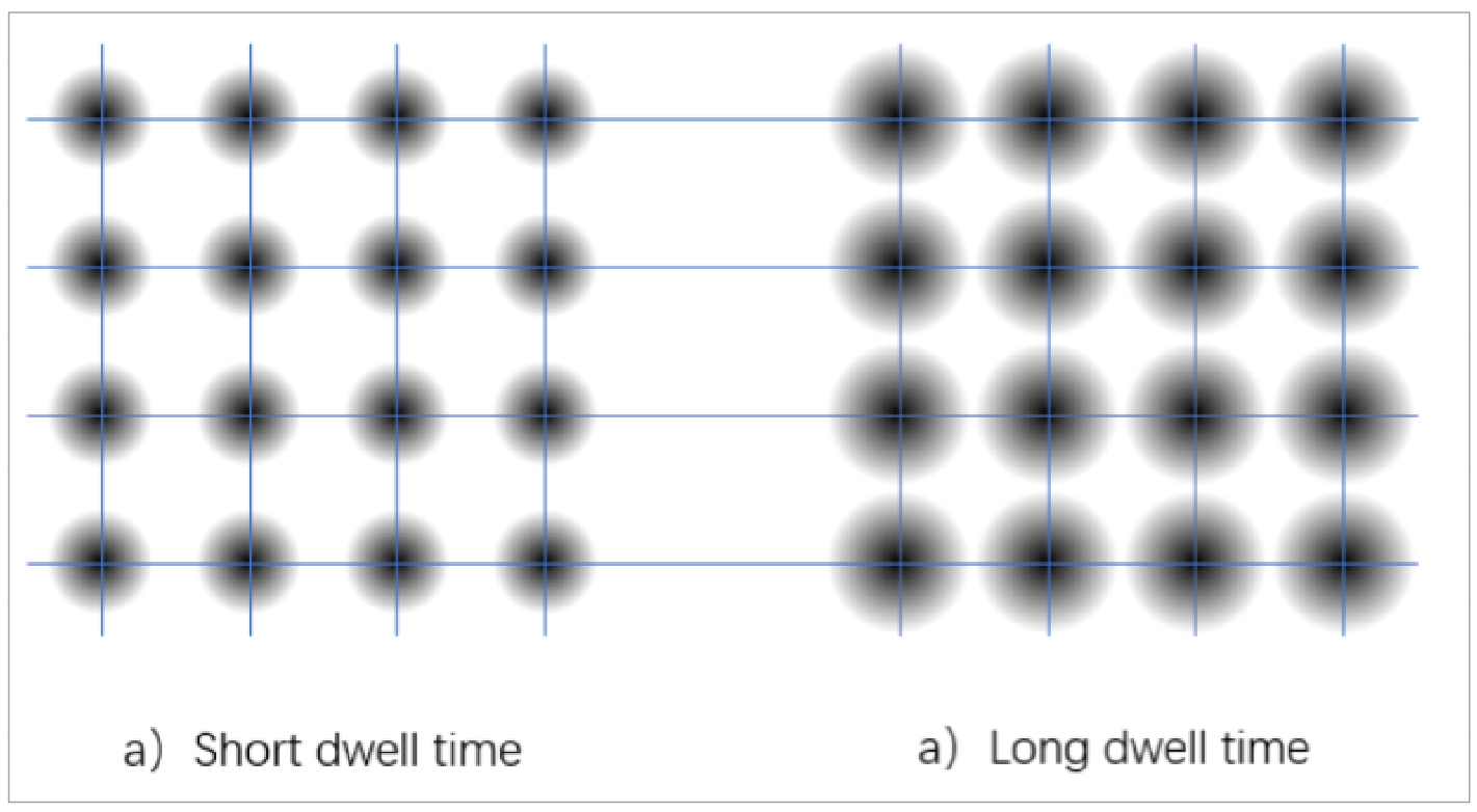
Dwell Time refers to the time for which a laser spot emitted by the toolhead stays on the workpiece during laser engraving and cutting. In laser engraving, when you select the Dot-filled Engraving mode, you can set Dwell Time. Both Work Speed and Dwell Time are used to control the time for which the laser with a fixed power stays on the workpiece, thereby controlling the laser energy absorbed by the workpiece. The shorter the Dwell Time, the lighter the engraving color.
Appears only when the Movement Mode is Dot.
Both Laser Power and Work Speed (Dwell Time) are vital to the effect of laser engraving or cutting, as they control how the workpiece is engraved and cut. When testing work parameters, it is recommended to adjust Laser Power together with Work Speed (Dwell Time) to determine an optimal combination, as the two parameters can restrict and affect each other.
¶ Pass
Appears only when the Processing Mode is Vector, or you add vector text.
¶ Initial Cutting Height Offset
Offset the cutting path in the Z-direction.
The initial cutting height is useful when cutting thicker materials, because it helps achieve cleaner and more precise cutting results. When cutting thick materials, the laser focus needs to be adjusted to a certain height below the surface of the plate. This ensures that the laser can effectively penetrate and cut through the thick material.
¶ Number of Passes
Set how many times the laser will trace the same path in a G-code file. A value between 1 and 5 is recommended.
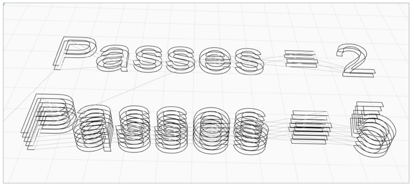
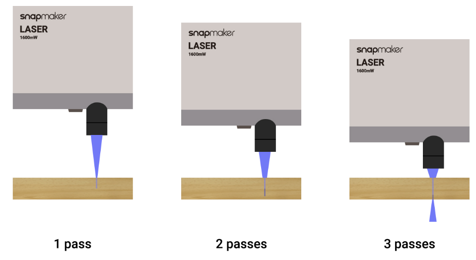
Generally, the laser beam emitted by the laser toolhead is in the shape of an inverted cone, and the focal point has the highest laser energy and cutting ability. To ensure that the focal point of each cut falls on the workpiece, the laser toolhead will lower by a certain height each time Number of Passes is increased so that the laser focal point can reach the workpiece. However, the laser toolhead cannot be lowered to a height where it is too close to the workpiece surface. Otherwise, the toolhead may bump against the workpiece. As the laser cuts deeper, the laser beam will be blocked by the workpiece on both sides, and the laser energy reaching the cutting position will taper off until it is unable to cut through the workpiece. Therefore, Number of Passes cannot be increased without limit.
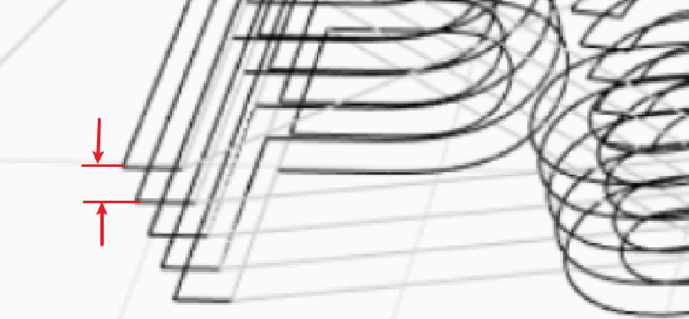
¶ Z Step per Pass
Set the amount at which the Laser Module is lowered with each pass. This setting is useful only when the machine engraves a multi-pass toolpath. The recommended value for the product of Number of Passes and Z Step per Pass is less than 5 mm.
¶ Power
Set the laser power to engrave or cut the object.
¶ Laser Power
Laser Power controls the amount of energy in the laser beam. It can be set as a percentage between 0% and 100%. In laser engraving, the higher the Laser Power, the darker the engraving color. In laser cutting, a laser with higher power can cut deeper, but it will also result in seriously charred edges.
Only with sufficient laser power can we engrave a clear pattern or cut through materials. However, excessive laser power may also cause trouble. It is crucial to keep the Laser Power parameter within an appropriate range.
¶ Constant Power Mode
In constant power mode, the laser does not change with the speed.
It is recommended to be turned on when cutting. And it is recommended to turn off when picture engraving.
¶ Half Diode Mode
For lasers that use multiple diode combining technology and support independent control of different groups of diodes, filter power control and smaller spot sizes can be achieved by turning on only one group of diodes.
Only available for 40W laser module.
¶ Optimization
¶ Dot Width Compensation
It is used to compensate for devaitions caused by the laser spot. It prevents excessive burning in image engraving situations. In the case of cutting, it guarantees more precise dimensions.

Excessive burning in image engraving and dimensional deviation in cutting caused by the laser dot offset have long been a headache for many. But now, with the parameter of the Dot Width Compensation available to configure, your machine is now able to optimize the toolpath based upon the size of the laser dot to reduce contour deformation and blurs.
¶ Over Scanning
Over Scanning is used to solve under and over burns from acceleration and deceleration phases.
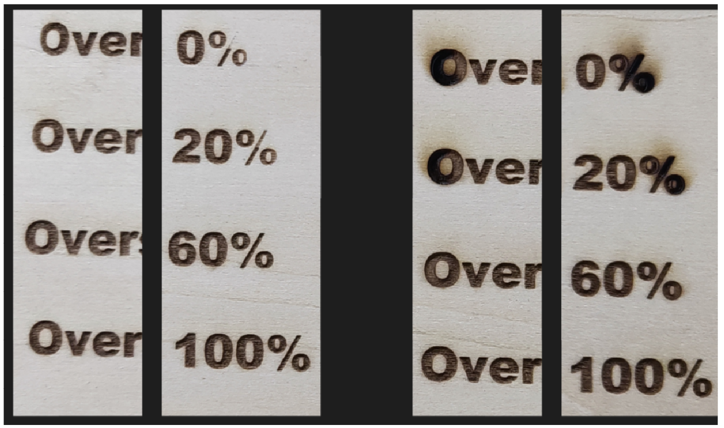
- If the work speed is set too high, the machine may not be able to achieve the target speed during machining due to acceleration constraints. This could result in insufficient engraving when the machine works in the dynamic power mode.
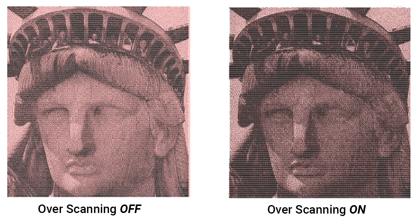
- To solve this problem, you can now adjust the Over Scanning ratio in the Line-filled engraving mode to ensure that the actual work speed of the machine is as close as possible to the target speed. Appropriate adjustment of this parameter will not only fix insufficient engraving in the dynamic power mode as mentioned, but also address excessive burning in the constant power mode.
- The underlying mechanism works by adding additional idle travel distance for the machine before it reaches the target speed. However, this also means sacrificing some machining travel distance, which might cause the machine to hit the limit switch if the overall travel distance exceeds the maximum work area. Therefore, we recommend being more cautious when adjusting this parameter.
¶ Scan Offset
You can tweak the parameter to compensate for the bidirectional scanning offset, which is caused by mechanical backlash and high-speed overshoot.
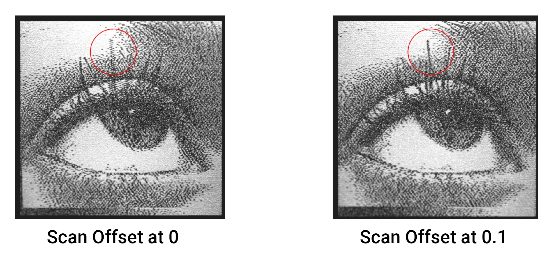
This feature works for the Line-filled engraving mode and is designed to impress you especially in cases where there is a large mechanical backlash or when the design to be engraved is intricate with rich details.
¶ Assist Gas
¶ Air Assist Pump
It can effectively increase the air flow rate over the laser focus point to achieve better cutting results.
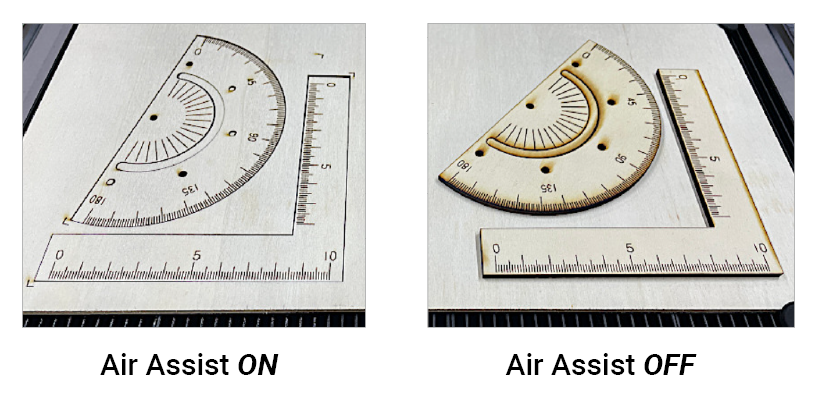
Only available in 20W/40W laser module.
It may give worse results for non-cutting conditions.