¶ 💡 Compatibility
This article applies to the following devices. Please take note when referencing:
Model: U1
¶ 📝 Problem Description
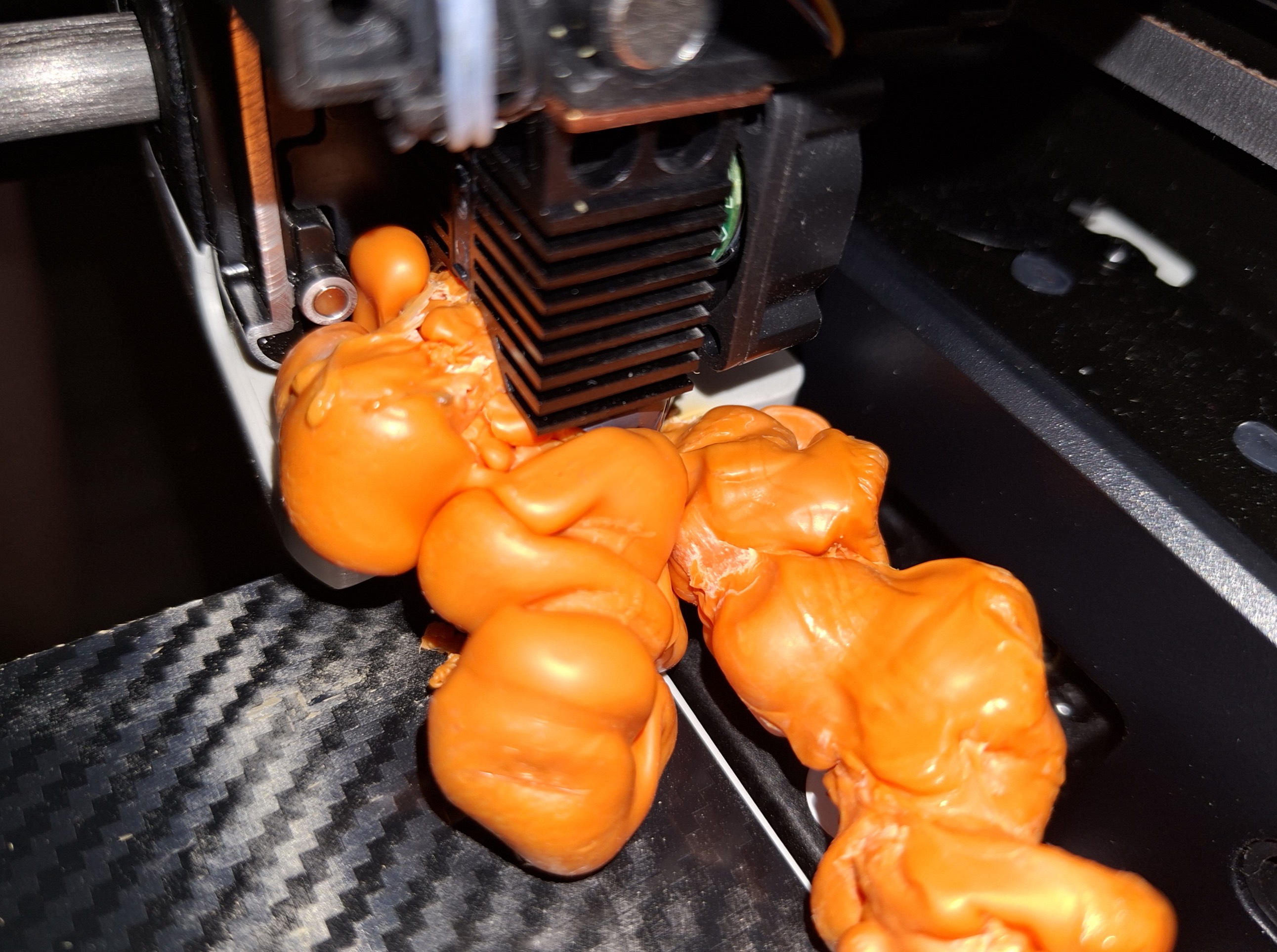
Extruded filament accumulates on the outer wall of the nozzle, gradually spreading to wrap around it;
This is often accompanied by issues such as the print detaching from the heated bed in the first few layers, the nozzle scraping the model, and layer shifting.
¶ 🛠️ Cleaning Method
If the nozzle can heat normally, please refer to the video tutorial to clean the blob first.
If a nozzle temperature error occurs or the hotend is damaged during cleaning, you can replace it with a new hot end, or purchase a ceramic heater and thermistor to use with the spare hotend in the accessory box.
Purchase links:
U1 0.4mm Stainless Steel Hot End
U1 Ceramic Heater 4-Pack
U1 Thermistor 4-Pack
¶ 🔬 Causes of Blob
¶ 1. Hotend Leakage
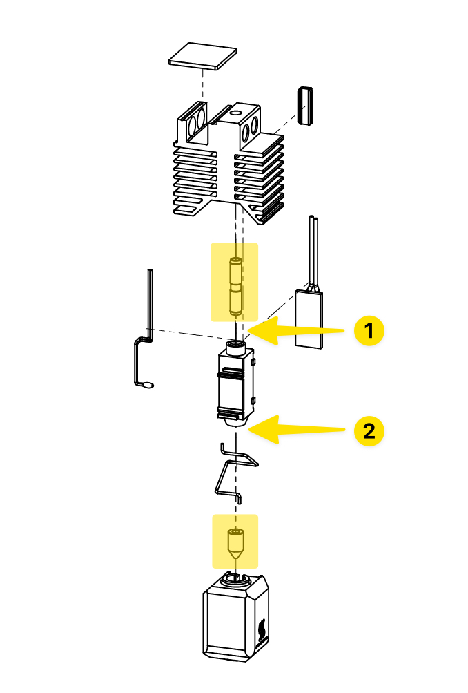
The hotend is assembled from multiple components, and assembly gaps may exist between them. When the gaps are large, molten filament seeps through and gradually accumulates to form a blob.
View Hotend BOM
If leakage occurs, it most commonly appears at Position 1 and 2 (the heat break and nozzle assembly points).
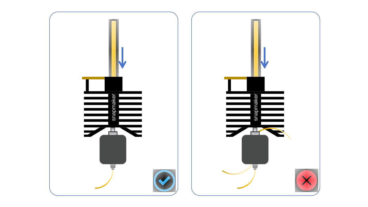
Preventive Measures
¶ 1. Check whether components are fully seated
Use a vernier caliper to measure the distance from the top of the hotend to the nozzle tip. Reference standard: 48 ± 0.2 mm.
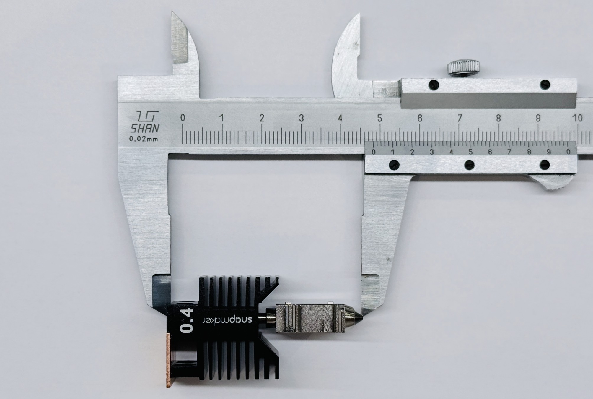
If the measurement is outside this range, replace the hot end promptly!
¶ 2. Clean the Nozzle
Check whether there is burnt black plastic around the nozzle and clean it off with a wire brush.
If burnt black plastic frequently appears on the nozzle exterior, replace the hot end promptly!
¶ 2. Nozzle too close to the heated Bed / model
¶ 1. Uneven Heated Bed
In certain areas of the heated bed, the top of the model is too close to the nozzle.
During printing, the nozzle plows across and peels the model off the bed while continuously extruding filament that wraps around the hot end.
Preventive Measures
-
Enable
Auto Levelingin print preference settings before each print.
-
If auto leveling is insufficient, perform manual bed leveling afterward.
-
Reduce the first layer print speed; recommended no more than 50mm/s.
¶ 2. Incorrect z_offset configuration
The relationship between the z_offset value and the nozzle-to-bed distance is approximately as shown in the diagram:
Effect of Z Offset on the Printing Process
When z_offset is too large, the nozzle is too close to the heated bed, forcing filament to overflow from the gap around the nozzle and bed, causing:
- Overflowed filament to creep upward and wrap around the hot end.
- The nozzle to scrape and peel the model off the bed while continuously extruding filament that wraps around the hot end.
Preventive Measures
-
After replacing the hot end, re-run the multi-toolhead offset calibration.
-
When using a third-party print platform, re-calibrate the Z offset.
¶ 3. Poor print platform adhesion
-
Print platform not cleaned and maintained regularly.
-
PEI steel sheet coating worn or contaminated.
Preventive Measures
-
Refer to How to Clean the PEI Steel Sheet and clean the print platform regularly.
-
The print platform is a consumable. Reduced adhesion after prolonged heavy use is
expected. If first-layer adhesion remains poor after ruling out hardware and process parameter issues, replacement is recommended.
¶ 3. Incorrect process parameters
A filament blob is usually caused by a combination of multiple incorrect process parameters. In the situations described below, it is recommended to stop printing and optimize the parameters.
¶ 1. Z_Offset too large + Flow ratio too high
Typical Symptom 1: Visible Material Buildup at Edges
Typical Symptom 2: Nozzle Scraping the Model
Optimization direction:
(1) Z Offset Calibration
(2) Flow Rate Calibration
¶ 2. Retraction distance too Short + Travel speed too high
Typical Symptom 1: Stringing
Typical Symptom 2: Wisps / Whiskers
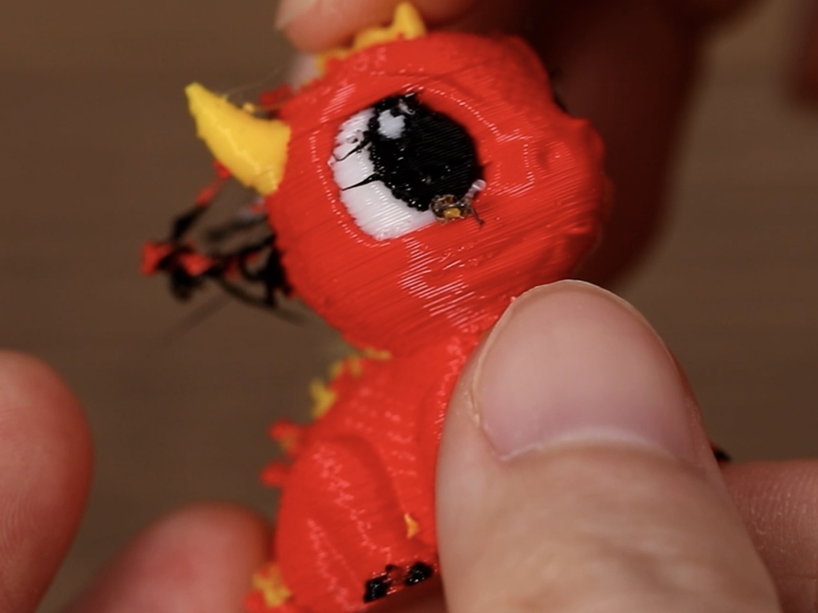
Optimization direction:
Refer to the following two wiki articles:
(1) Stringing or Oozing
(2) Filament Adhesion to Nozzle
¶ 3. Damp filament + Nozzle temperature too high
Typical Symptom 1: Surface Pitting / Pinholes
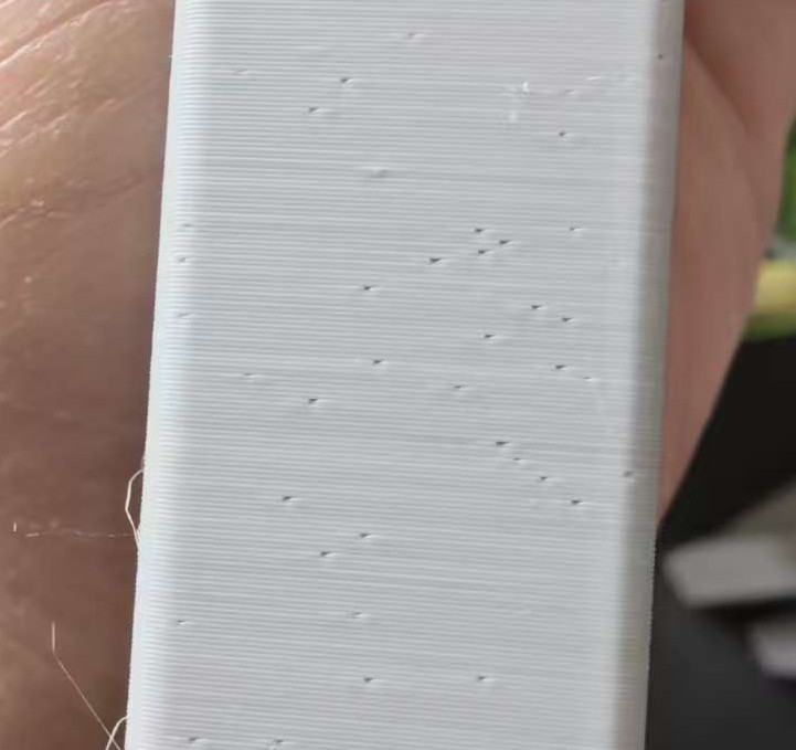
Typical Symptom 2: Stringing
Optimization direction:
Refer to the following two wiki articles:
(1) Stringing or Oozing
(2) Pitting and pockmarks
General Preventive Measures
-
When using third-party filament, perform temperature and flow calibration on top of the generic filament profile.
-
Optimize pressure advance and retraction parameters based on actual print results.
-
Monitor first layer print quality and stop the machine promptly to make adjustments.
¶ ↕️ How to Calibrate Z_Offset?
If you are using the official print platform, z_offset calibration is usually not required, but please ensure the bed type is set correctly before slicing.
If you are using a third-party platform, its rigidity may differ significantly from the official platform. You can perform z_offset calibration to achieve better print quality.
¶ 1. Overview
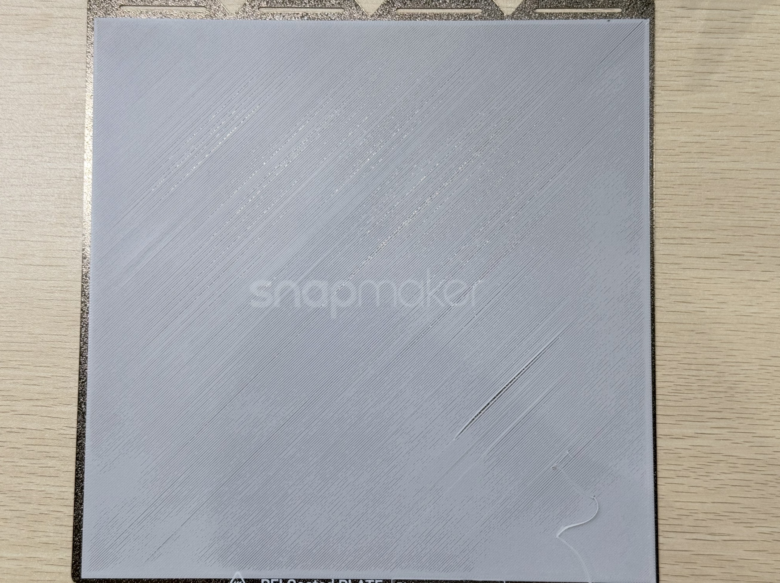
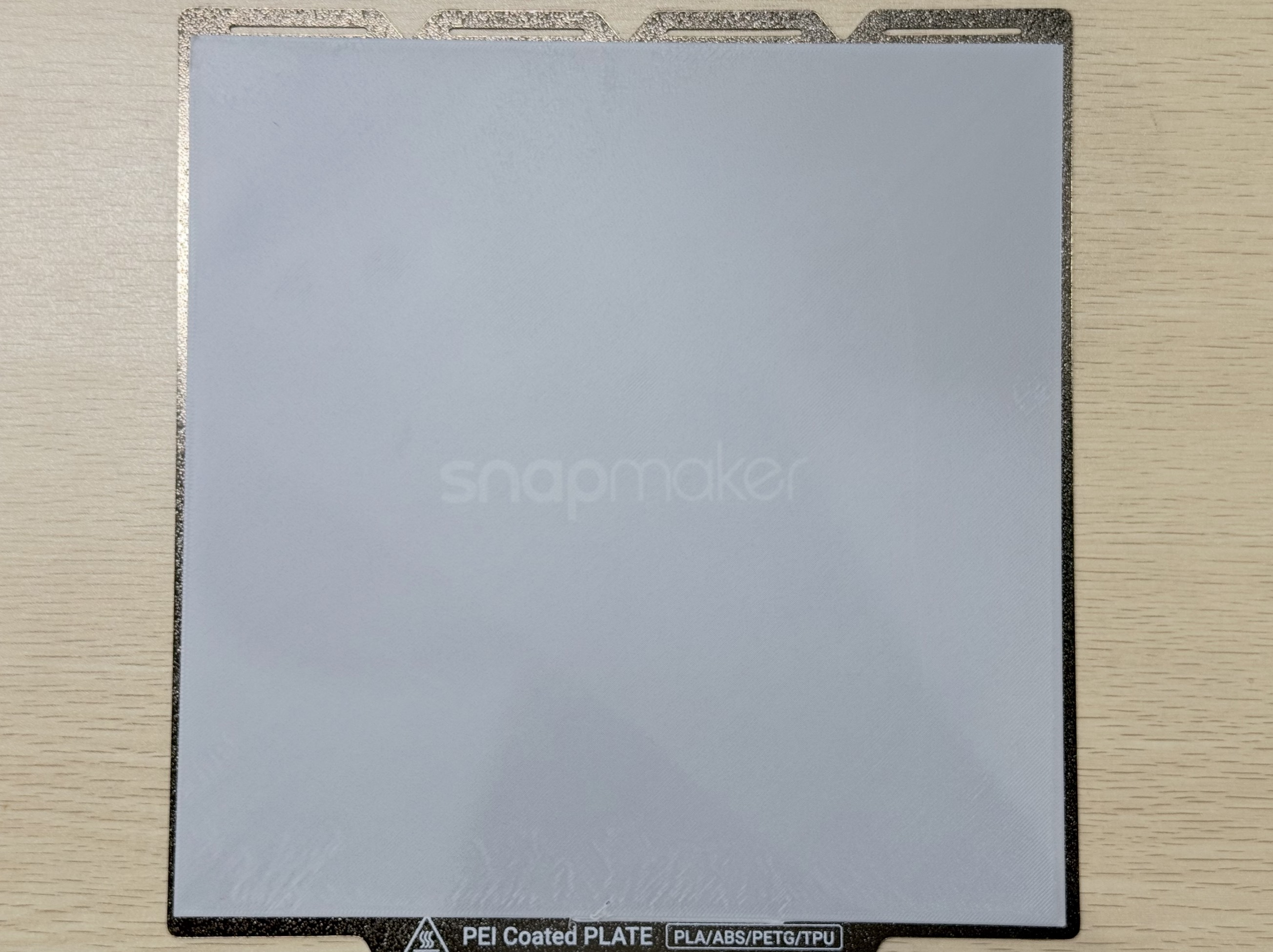
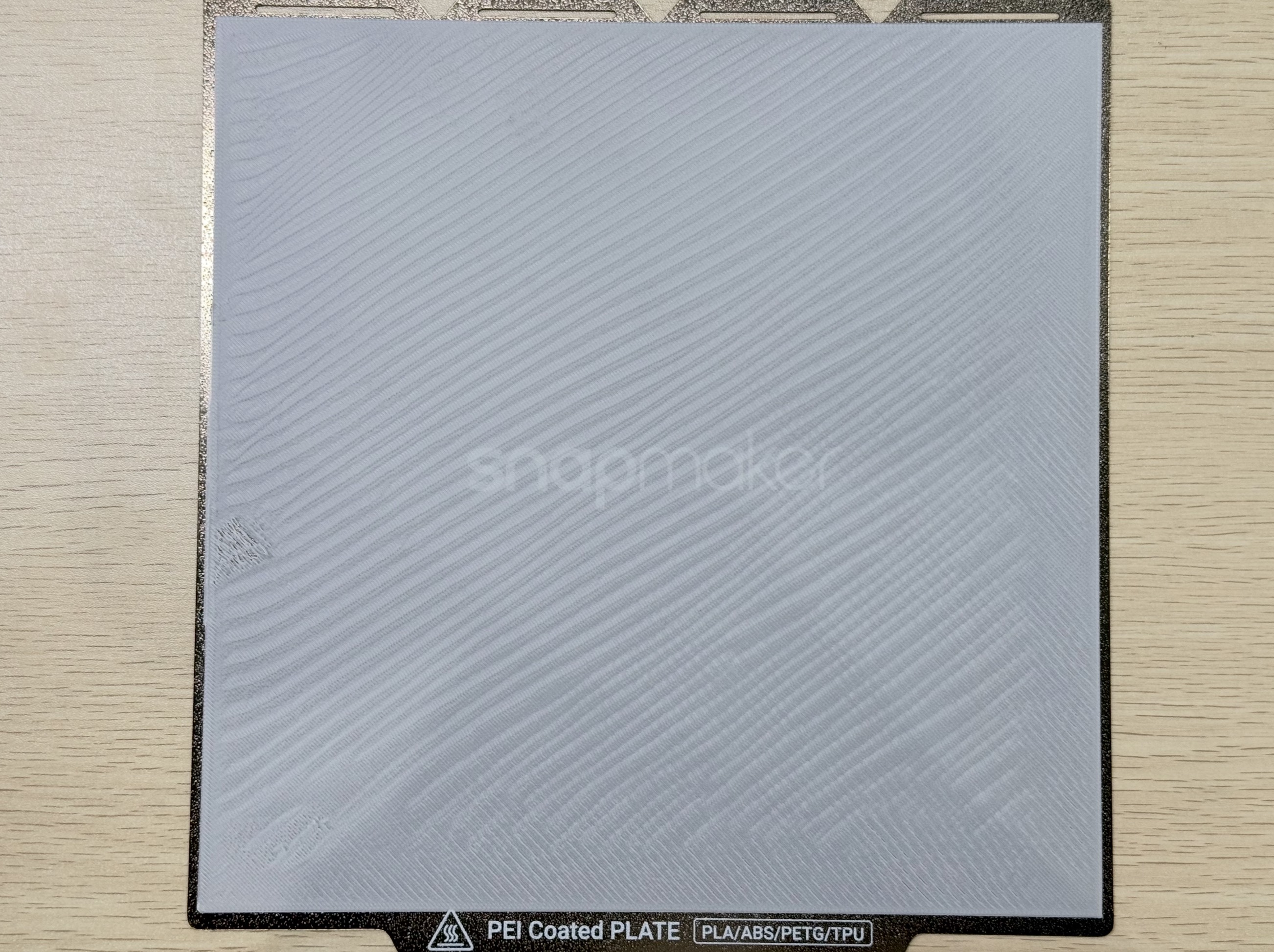
The default z_offset is -0.05. Printing a full XY-size first layer can reveal whether the current z_offset value is appropriate, for example:
-
First layer lines are sparse with visible gaps: Z_offset too small
-
First layer is uniform and smooth with minor imperfections (area ≦10%): Z_offset appropriate
-
First layer shows wrinkles or wave patterns: Z_offset too large
Adjust Z_offset based on print results until the first layer appearance is close to the middle example shown.
¶ 2. Steps
Using PLA + PEI textured steel sheet as an example.
-
Import the 270 × 270 × 0.2mm model into Snapmaker Orca.
-
Select Snapspeed PLA as the filament and
0.20 Standard @Snapmaker U1as the process profile. Enable bed leveling and send the print. -
Based on the print result, determine whether the current z_offset is too large or too small, then adjust it in increments of 0.01 and reprint. Always enable
Heated Bed Levelingeach time; otherwise the updated z_offset cannot be verified.
¶ 3. Z_offset Location
There are typically two places where the Z offset can be modified. Either one can be used.
¶ 1. Printer Configuration File
- Enable Advanced Mode.
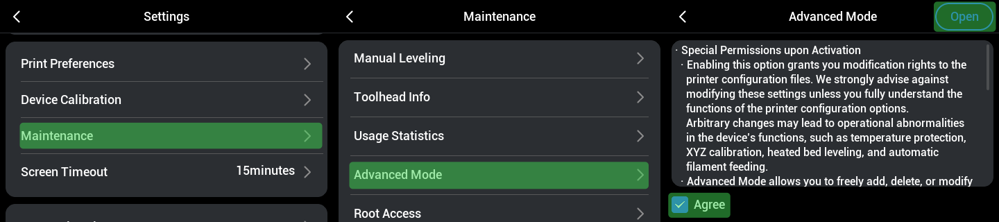
Enabling Advanced Mode for the purpose of z_offset calibration as described in this article has no effect on your machine's warranty.
-
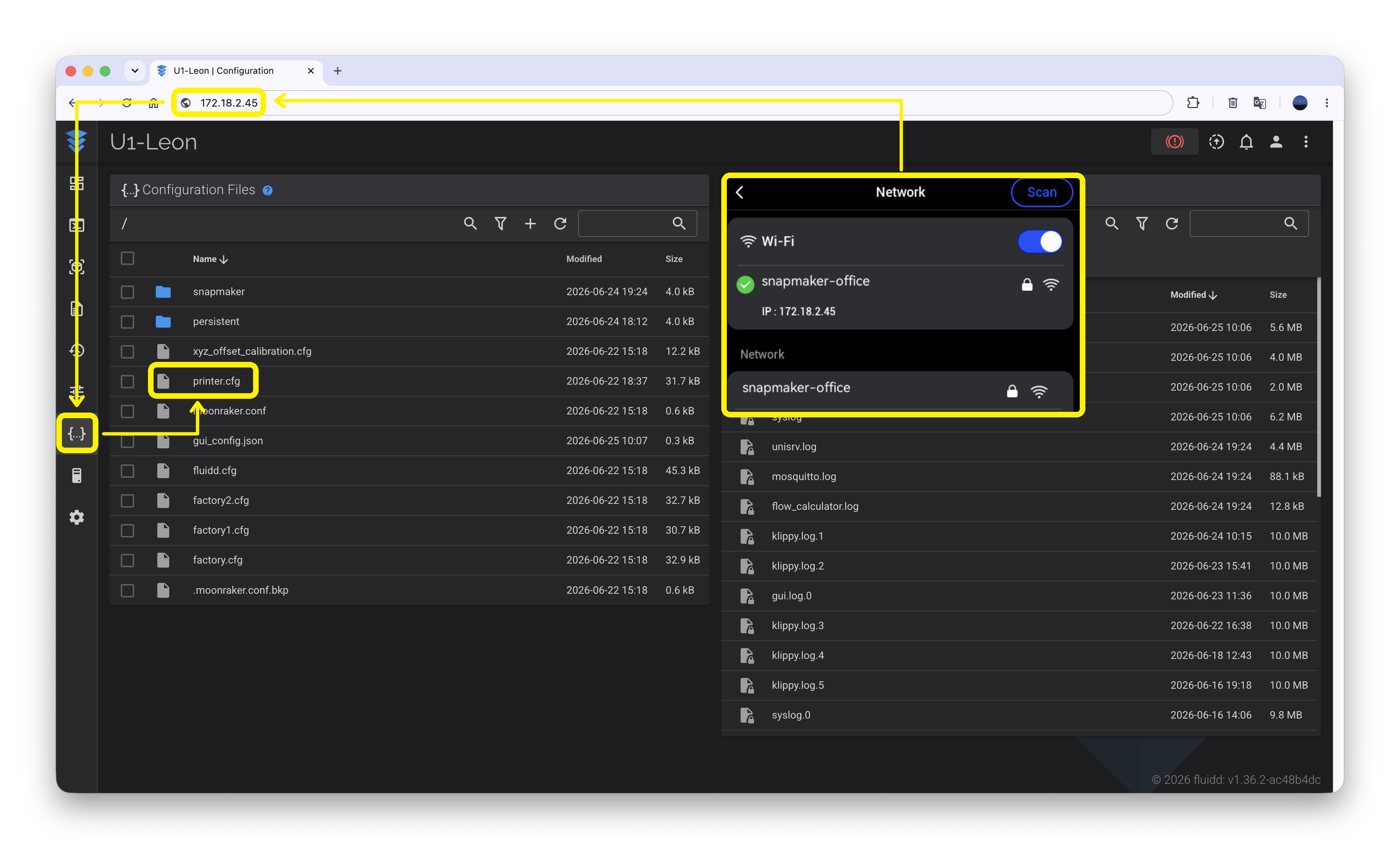
Connect your computer and the machine to the same Wi-Fi network.
-
Enter the machine's IP address in a browser to access Fluidd, then open
Printer.cfg.
-
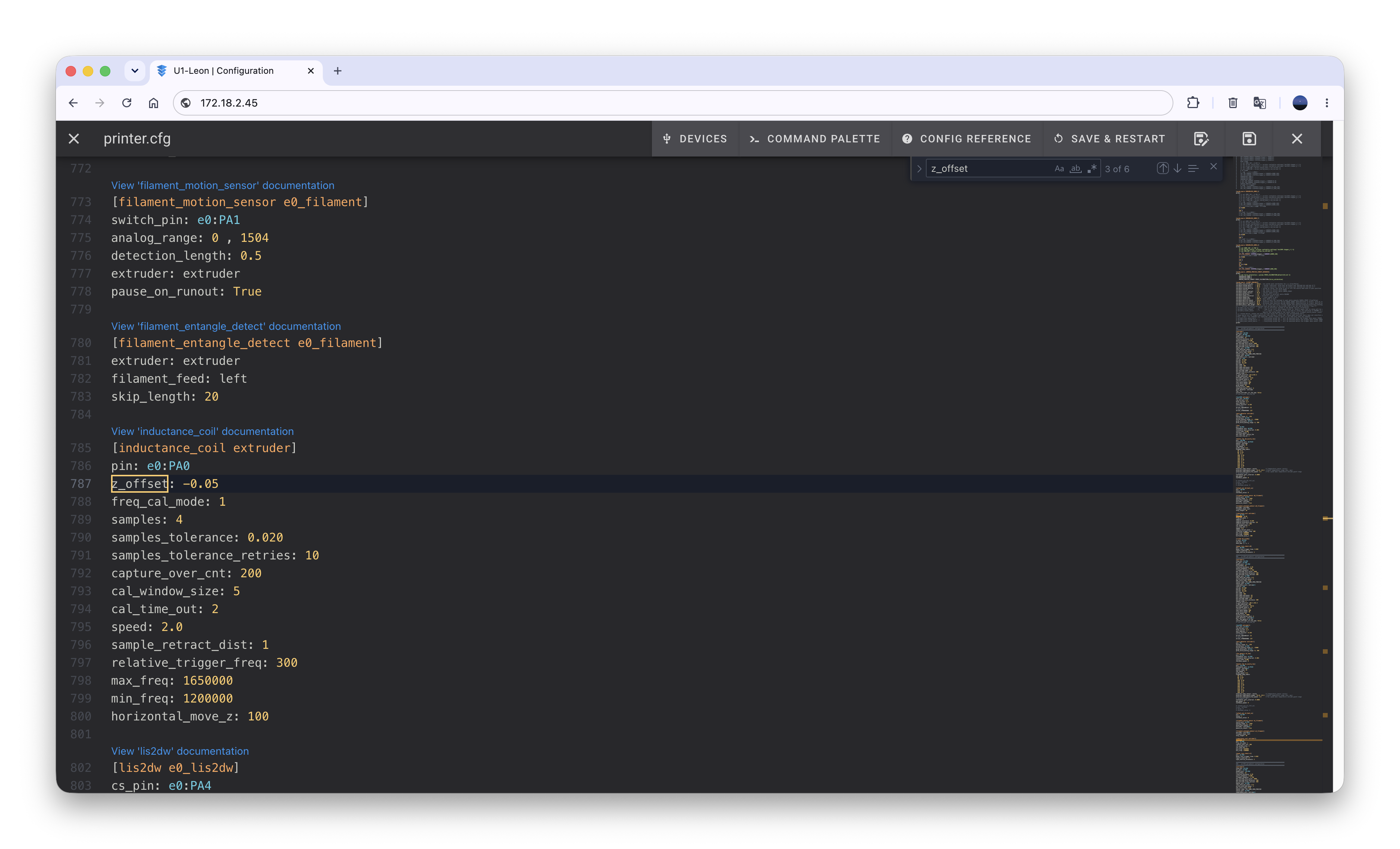
Press
Ctrl/Command + Fto open the search box, typeZ_offset, and press Enter to locate the parameter — it is typically on line 787.
-
After making changes, click
SAVE & RESTART.
¶ 2. Printer Start G-code
(1) Open the G-code generated by Snapmaker Orca in Fluidd.
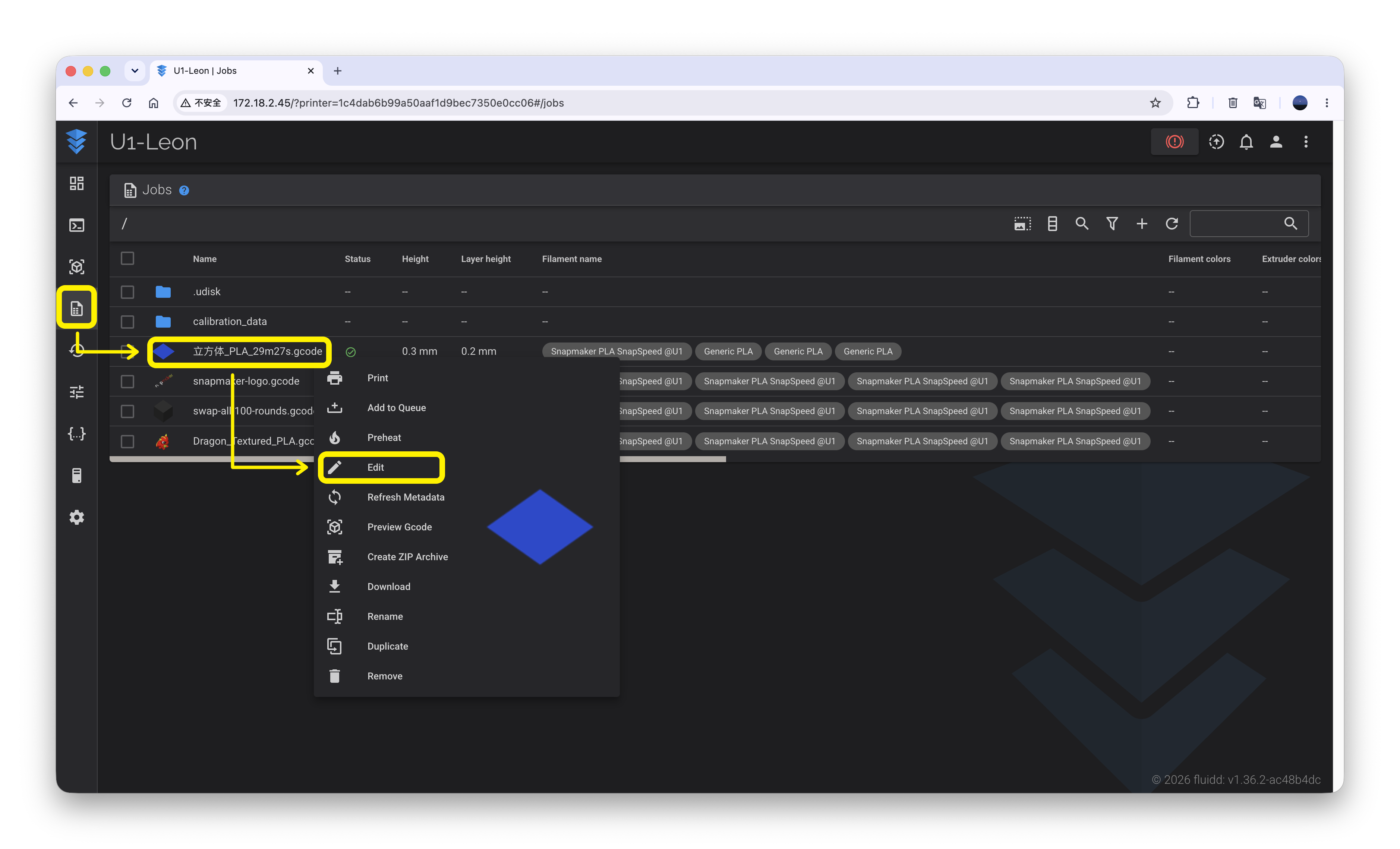
(2) At lines 145 and 151, you will find two commands:
-
G28 Z: Home the Z axis. -
BED_MESH_CALIBRATE PROBE_COUNT=11,11: Auto bed leveling before printing.
You can add commands at these two locations to adjust the z_offset. For example, to set the z_offset to -0.03:
- After
G28 Z, addz_offset -0.03. - After
BED_MESH_CALIBRATE PROBE_COUNT=11,11, addz_offset=-0.03.
Note: between z_offset and -0.03, one uses a space and the other uses an equals sign.
- Save and exit.
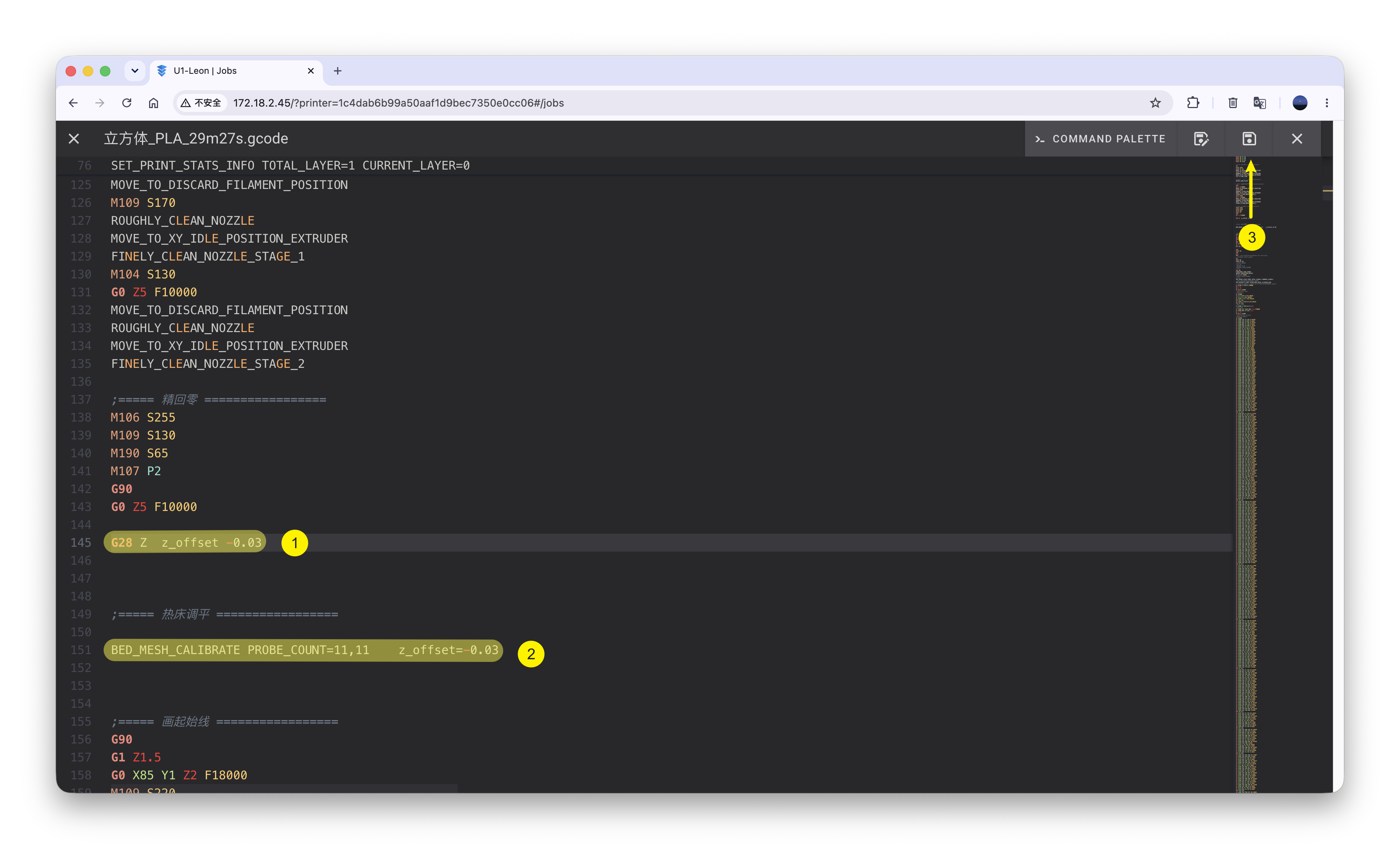
- Re-run the G-code to verify the effect of the adjusted z_offset.
(3) You can add the calibrated z_offset to the machine's start G-code and save it as a user preset. When printing with a third-party platform in the future, use this preset for slicing.
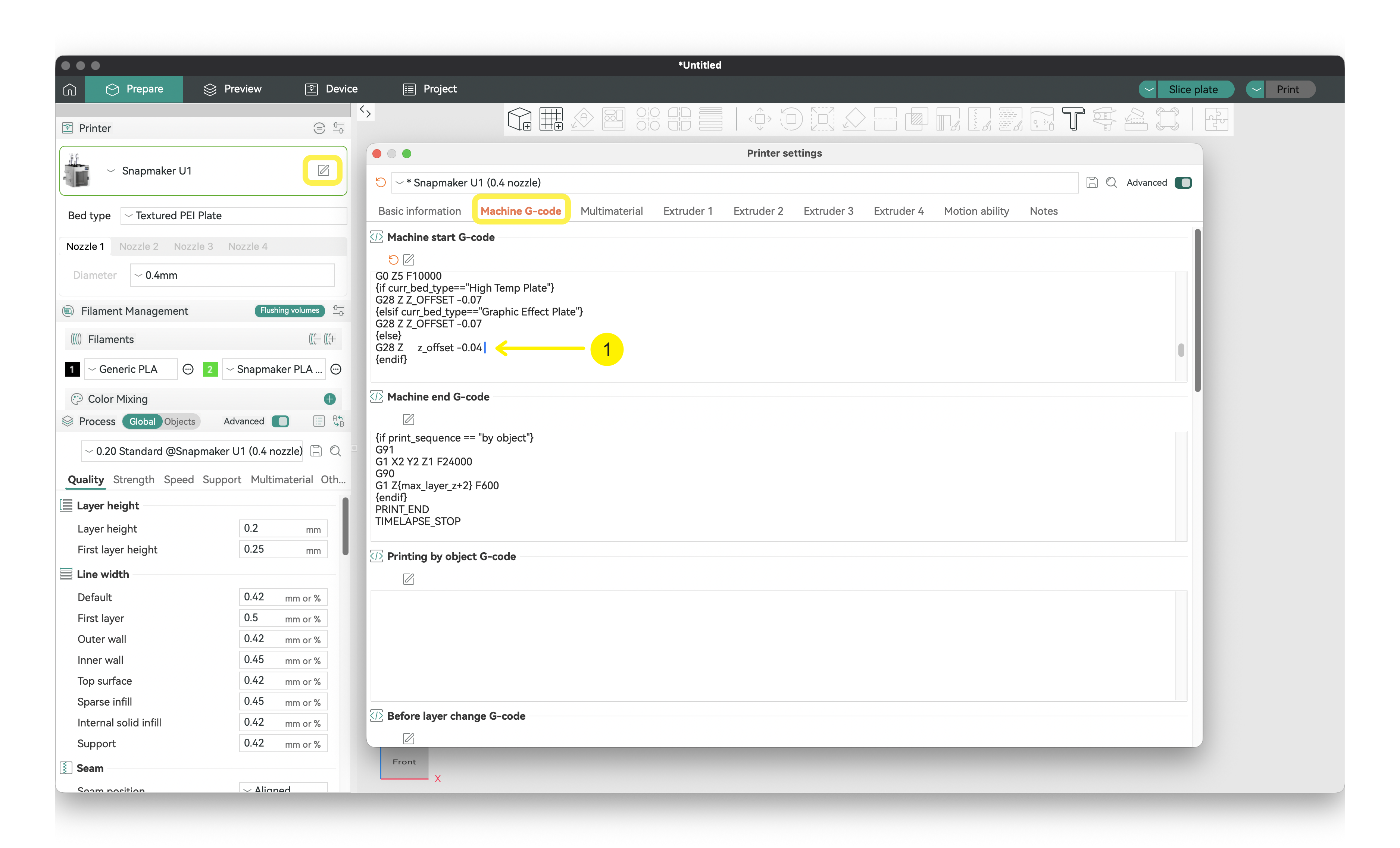
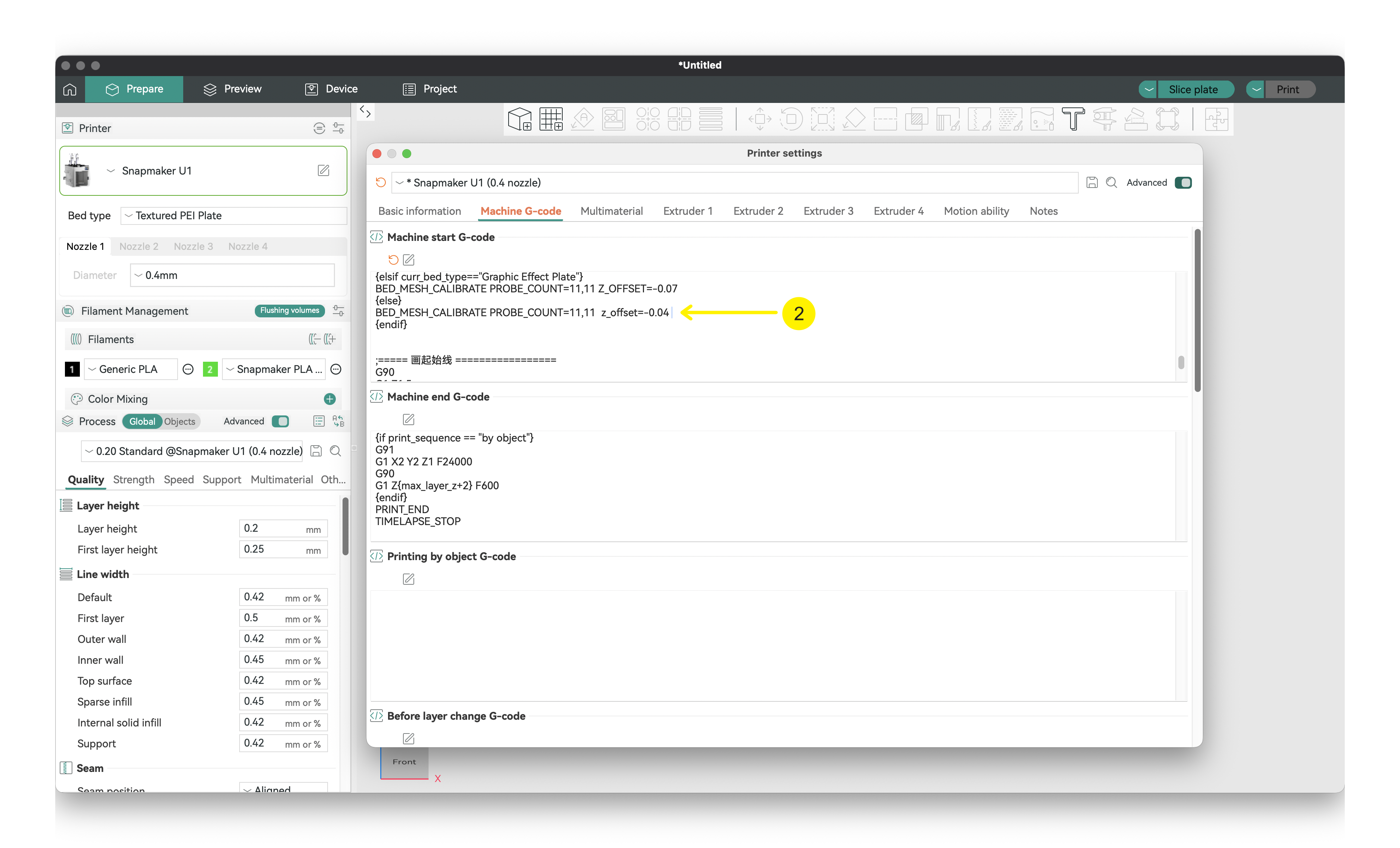
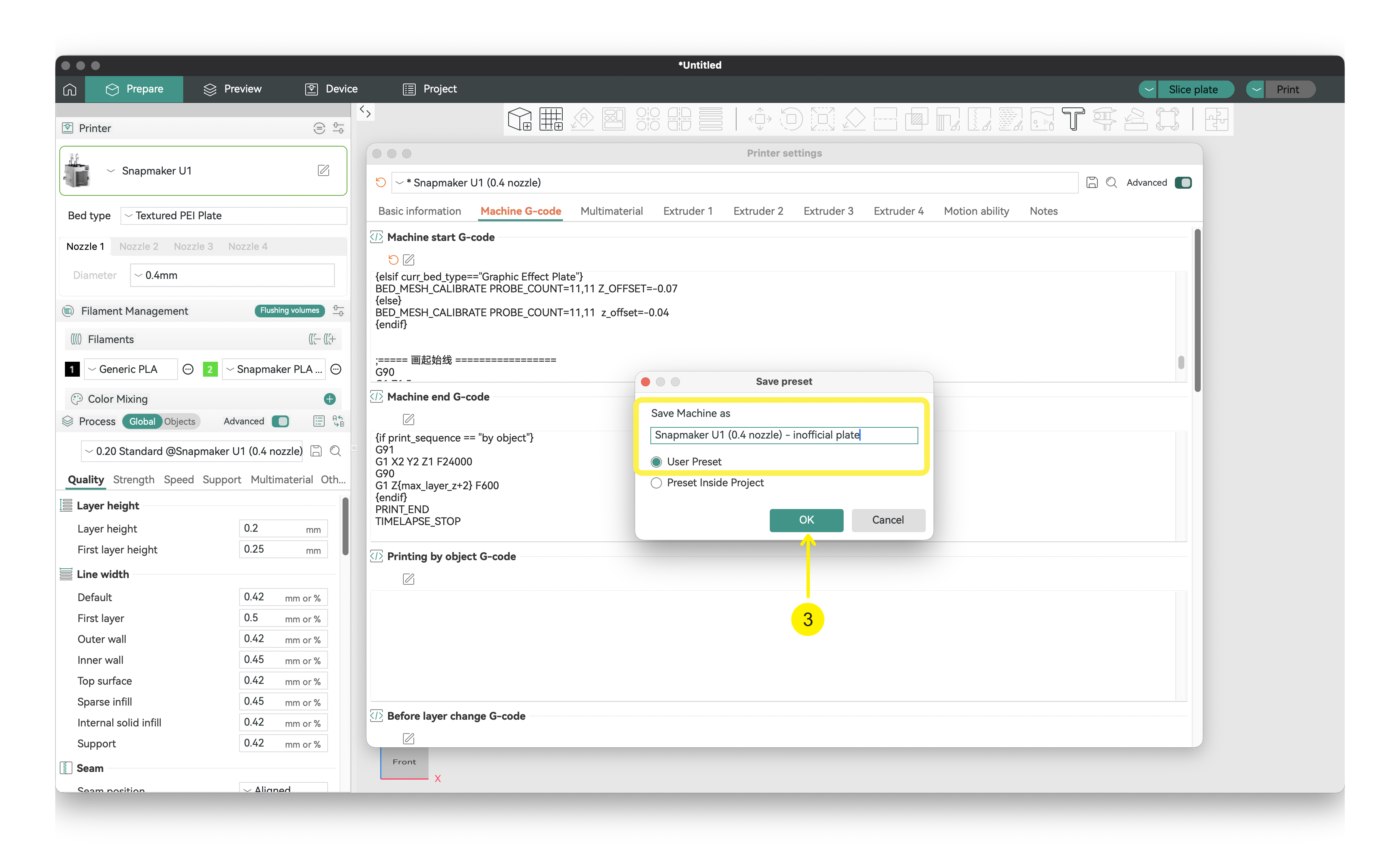
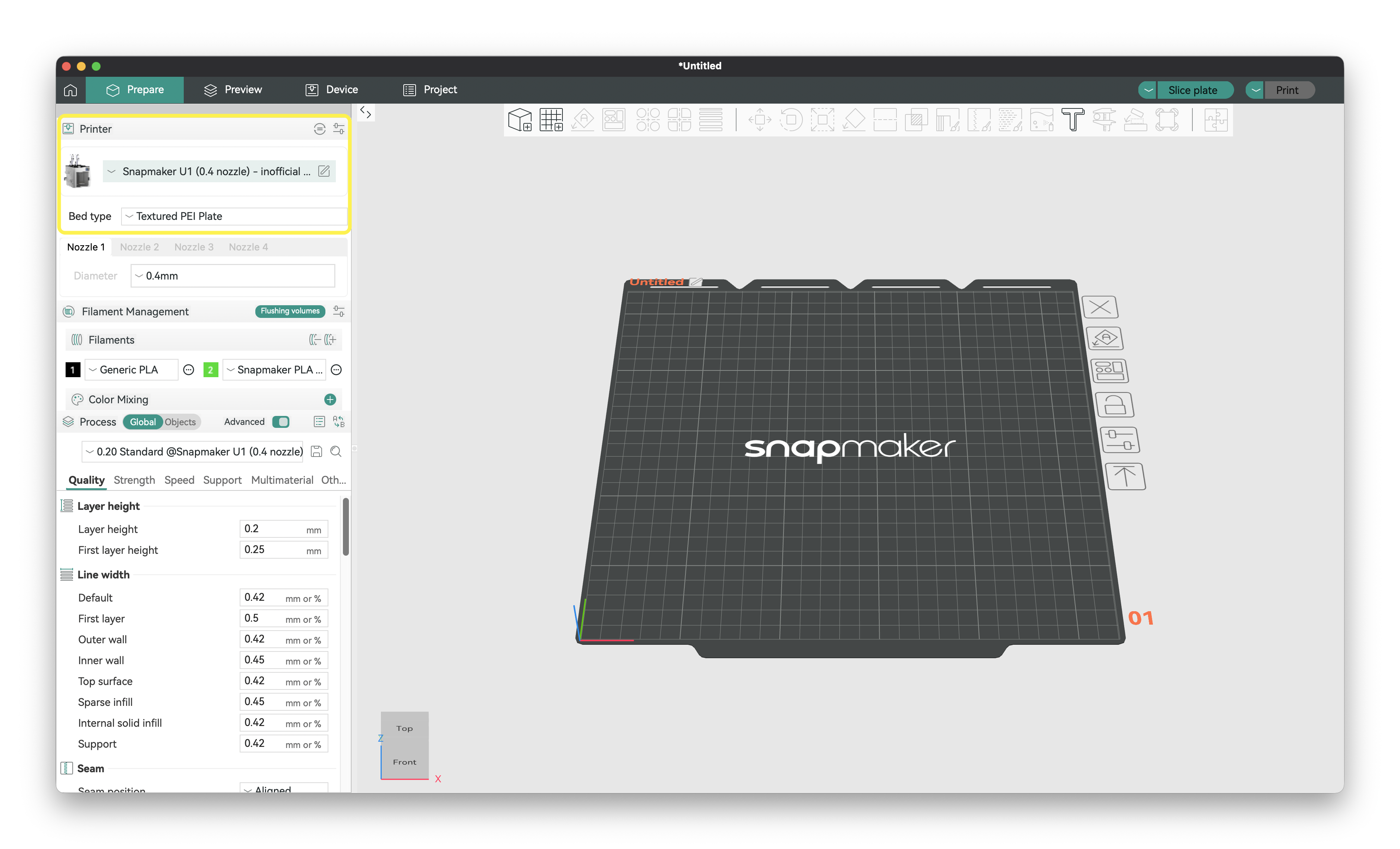
If the z_offset is modified in both the machine configuration file and the printer start G-code, the latter takes higher priority.