3D printing parameters refer to various settings and configurations that control the 3D printing process. These parameters althogether can determine print quality, material efficiency, mechanical properties, print time, printer longevity and so on.
Luban provides over 300 print settings, which can be further divided into effiency-related, strength-related, quality-related, accuracy-related, material consumption and printing success. This article aims to explain the meaning of each material parameter and what effects they can achieve.
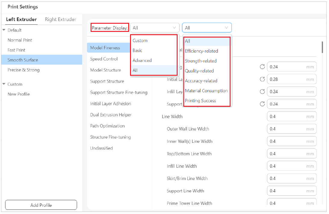
You can choose which print parameters are displayed.
- On one hand, clciking the Parameter Display dropdown list, you can choose between different parameter categories such as Custom, Basic, Advanced, or view all parameters.
- On the other hand, you can also choose to display the parameters that are most relevant to your specific printing needs, whether it be efficiency, strength, quality, accuracy, material consumption, or overall printing success.
- In addition, Luban also allows you to customized display, refer to - Customize print setting parameter display.
You can customize these parameters to achieve better printing results, refer to - Adjust print setting parameters in Luban.
If you need to add new print profile, refer to - Add print profiles into Luban
¶ Model Fitness
¶ Layer Height
Description
Set the thickness of each layer. Printing at a thicker layer height can decrease your printing time, at the cost of a smooth surface and rich details. On the flip side, printing at a thinner layer height increases the printing quality, gives a smoother surface, and allows more detail. However, it will cost you much more time.

It is recommended to keep the layer height between 25% and 75% of the nozzle size.
Influence
-
Having thinner layers will:
(1) increase the smoothness of the print;
(2) reduce the stair stepping effect at the layer's borders. -
Having thicker layers will:
(1) make the print stronger;
(2) give better-quality overhangs;
(3) reduce printing time.
Many settings depend on the Layer Height. Because Layer Height significantly affects the flow rate of material through the nozzle, many parameters of the printing process will change.
Additional notes
At very low layer heights, you could run into the resolution limit of your Z axis. Look up the step size of your printer's Z axis and make sure that the layer height is a multiple of the step size. If the step size and layer height don't match up properly, some layers will be thicker than others which will result in banding.
Note that the layer height setting is not applicable to the initial layer of the print or for the raft layers, which have their own settings to adjust the layer height separately. When using adaptive layers, this layer height setting will be used as a baseline but the actual layer height will have some variation.
¶ Initial Layer Height
Description
This setting defines the thickness of the first layer of your print. When printing starts, 3d printer will use the first layer height value to print the first layer of a model and then use the Layer Height value to print the remaining layers.

Usage
The initial layer is normally printed thicker than the rest in order to create a stronger adhesion with the build plate.
Having too thick of an initial layer causes the first layer to sag more, which causes elephant's feet. The Initial Layer Horizontal Expansion setting can prevent the elephant's feet by setting a small negative value.
¶ Infill Layer Thickness
Description
This setting causes multiple infill layers to be combined together. When this setting is enabled, the toolhead will then not print any infill on some of the layers, but in the highest of the combined layers it will extrude more material to make up for it.
In layer view, it will look as if the infill lines have become much wider. When actually printed, the infill lines will drop down further instead of spreading out horizontally.

Usage
Since the layer height of the infill is not important for visual quality, you can use thicker layers for the infill to reduce the printing time.
The Infill Layer Thickness must be a multiple of the ordinary layer height. Otherwise, this setting will be rounded to the closest layer height.
Be careful with increasing this setting too much. When switching to and from infill, the flow rate through the nozzle needs to accelerate and decelerate significantly. There is some delay on the acceleration and deceleration, so the nozzle will extrude too little at the beginning of the infill and too much after the end of the infill.
In the in-between layers, the toolhead will still print infill with a lower layer thickness where there is no infill in the layers around it. This can cause small lines of infill to be printed alongside sloping walls.
¶ Line Width
Description
This is the horizontal width of the lines that the printer will place down. Normally the diameter of the nozzle opening determines how wide your lines will be, but by extruding more or less material, the printer can vary a little bit in how wide the lines will become.

It's not advisable to reduce the line width below 60% of the nozzle size or above 150%. Both may fail to extrude enough material.
¶ Outer Wall Line Width
The width of a single outer wall line.
The line width for the walls can be adjusted separately from the rest of the print.

¶ Inner Wall(s) Line Width
The width of a single inner wall line.
The line width for the walls can be adjusted separately from the rest of the print.
¶ Infill Line Width
The line width of all infill material.
¶ Top/Bottom Line Width
The line width with which the top and bottom layers are printed.
¶ Skirt/Brim Line Width
The width of the skirt or brim lines.
¶ Prime Tower Line Width
The width of a single prime tower line.
¶ Speed Control
¶ Print Speed
The print speed defines the speed (in mm/s) at which the print head moves while printing.
A higher print speed will lead to a shorter print time. Note that increasing the print speed means that you may have to increase the temperature as well to ensure the filament is properly melted.
You can set different print speeds for specific parts of the print:
¶ Infill Speed
The speed at which the infill material is printed. If the visual quality of the infill is not important, you could use a higher speed for the infill. However, keep in mind that this may affect the strength of your print.
¶ Outer Wall Speed
The speed at which the outer walls are printed. Printing the outer wall slower usually results in a better surface finish.
¶ Inner Wall Speed
The speed at which the inner walls are printed.
¶ Overhanging Wall Speed
With this setting, the speed can be adjusted at which overhanging walls are printed. The speed is set as a ratio of their normal print speed, which is either the Outer Wall Speed or the Inner Wall Speed.
Printing overhang at lower speeds can be very effective to reduce droop.
¶ Top/Bottom Speed
Top/Bottom Speed refers to the speed at which the top and bottom side of the model is printed. This setting can be configured separately from the normal print speed.
This setting has no significant effect on the build plate adhesion. The Initial Layer Print Speed is used for the first few layers.
¶ Prime Tower Speed
This setting configures the speed at which the prime tower is printed.
It's usually good to print the prime tower at a similar speed as the rest of the print, so that the material gets primed properly. However, printing the prime tower slower will make it more stable as well, which can be useful for runny materials or very tall prints.
¶ Travel Speed
This is the speed at which the toolhead moves when it is not extruding.
A higher travel speed reduces the chance of filament oozing from the nozzle, resulting in a cleaner print. However, increasing the speed can also cause the nozzle to collide with previously printed parts, potentially damaging the print due to the heated nozzle. This can be mitigated by using Z-hop during retraction. Additionally, very high travel speeds may lead to accuracy issues.
The travel speed for the initial layer is different from the rest of the print to ensure proper adhesion to the build plate.
¶ Enabled Acceleration Control
This setting configures how fast the toolhead should accelerate.
Acceleration is a very important part of printing. Just like a car, the print head needs to accelerate to get to the speeds as explained above.

Influence
-
The toolhead will reach the desired speed sooner, which ensures faster print, especially when printing small parts.
-
The toolhead will reach the desired speed sooner, which ensures faster print, especially when printing small parts.
Usage
Normally the printer decides by itself how fast the toolhead should change direction and speed, but if this setting is enabled, Luban can decide this instead, which allows you to set different acceleration rates for each feature of a print.
¶ Enable Travel Acceleration
¶ Print Acceleration
Desciption
This setting refers to the acceleration rate of toolhead towards the desired velocity when starting, stopping or changing direction. Just like a car, the toolhead needs to accelerate in order to change its speed or direction.

Influence
Increasing this setting has the following two effects:
-
The toolhead will reach the desired speed and direction sooner, which ensures faster print, especially when printing small parts.
-
More vibrations will occur, which will reduce dimensional accuracy and cause ringing.
¶ Infill Acceleration
This setting controls how fast the nozzle accelerates into different directions while printing the infill.
The Infill Acceleration can be set to a different rate than the rest of the print.
Acceleration has a big impact on printing time for infill lines. And since the infill is on the inside where it is not visible, adjusting this setting tends to have a low impact on the visual quality of the print. Therefore, it is common to set the acceleration rate for infill higher than the acceleration for the rest of the print.
¶ Outer Wall Acceleration
This setting controls how fast the nozzle accelerates into different directions while printing the outer walls.
The acceleration during the outer walls can be set to a different rate than the inner walls.
As the outer walls are very visible from the outside, it's common to have the outer walls printed with a lower rate of acceleration than the inner walls, which will increase the printing time though.
¶ Inner Wall Acceleration
This setting controls how fast the nozzle accelerates into different directions while printing the infill.
The Infill Acceleration can be set to a different rate than the rest of the print.
Acceleration has a big impact on printing time for infill lines. Therefore, it is common to set the acceleration rate for infill higher than the acceleration for the rest of the print.
¶ Top/Bottom Acceleration
This setting controls how fast the nozzle accelerates into different directions while printing the top and bottom of the object.
The Top/Bottom Acceleration can be set to a different rate than the rest of the print.
Increasing this setting will have the following two effects:
-
Increasing this setting compared to the rest of the print can save some time. Since the top and bottom sides typically consist of long straight lines, the nozzle can reach great speeds during printing. The nozzle must also make sharp corners with the typical lines pattern for the skin, which requires great acceleration.
-
However, increasing this setting will cause the printer to shake more as well, but the accuracy of the top and bottom sides is not normally a constraint because they are surrounded by walls.
¶ Prime Tower Acceleration
This setting controls how fast the nozzle accelerates into different directions while printing the prime tower.
The Prime Tower Acceleration can be set to a different rate than the rest of the print.
Increasing this setting allows the extrusion to be more constant, allowing for better priming. A higher acceleration rate for prime tower also reduces printing time. However, the prime tower may topple more easily if the acceleration rate gets very high and the printer vibrates a lot during its printing.
¶ Travel Acceleration
This setting controls how fast the nozzle accelerates into different directions while travelling across the build volume.
The Travel Acceleration can be set to a different rate than the rest of the print while material is extruded.
Since the printer is not extruding any material during the fast travel moves, any vibrations of the printer don't have any real effect on the print. As a result, the Travel Acceleration should be set relatively high to save printing time.
Setting the Travel Acceleration rate too high can cause the motors to lose some steps, leading to layer shifts.
¶ Model Structure
¶ Model Structure Type
This setting allows you to choose which type of structure you want to print.
By default, Luban uses Normal Structure to print the model. With this selection, all parts of the model will be printed integrally.
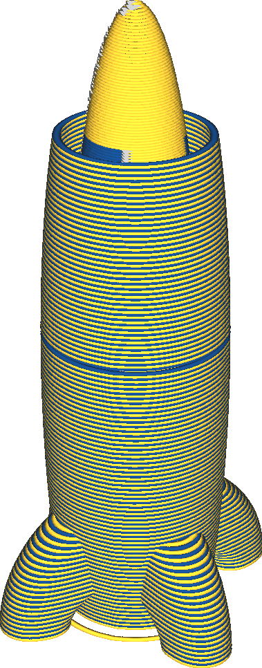
Vase Structure, also called Spiralize Outer Contour/Vase Mode, prints only the bottom layer and the outer wall of the model. The structure of the print is similar to that of a vase, with a bottom and a wall, but with no infill or top cover. The model is built by a continuous smooth movement of the z-axis. There are no travels, no retractions. And there is no starting point and end point in the perimeter of each layer, and there is no "scar" like seams on the surface of the model, which can greatly improve the quality of the model surface.
Vase Structure has the following effects:
-
Prints extremely fast.
-
The surface becomes very smooth. There is no Z seam any more where it moved to the next layer.
-
The model will not be very strong. If the model is too big, it tends to split due to warping.
-
It is difficult to get the print to be watertight if it is large.
Vase mode is great for printing things like lamp shades, rockets, containers, pyramids, sculptures and so on.
Vase Structure will not work well with prints with many horizontal surfaces. It doesn't handle overhangs at all, and doesn't print top surfaces so nothing will be able to lean on a horizontal surface. It also doesn't work well when there are multiple parts on a layer.
¶ Bottom Thickness
This setting configures how thick the bottom layers of the print will be.
Different from the normal layers that are made up of walls and infill, the bottom layers are solid layers. They are fully printed so as to close the gaps at the print bottom.

The left model has thinner bottom layers, while the right one has thicker bottom layers.
By increasing the thickness of the bottom layers, you can achieve the following effects:
-
Your print will be more watertight. The bottom layers can close gaps on the bottom side of your print.
-
Your print will be stronger. Having more bottom layers will mean that your print will be made more firm, with less infill and more solid layers.
-
Your print will cost more time and material.
¶ Initial Bottom Layers
Initial bottom layers refer to the print's bottommost layers that rest on the build plate.
The initial bottom layers are part of the bottom layers. However, you can configure different settings for the initial bottom layers from the rest of the bottom layers.
By adjusting settings for all the bottom layers, you can make the print watertight, hide the infill from sight, and improve model strength. However, that will also cost more material and time.
If you adjust those settings only for the very bottom layer or two, you can still get a watertight model with little shine-through effect of the infill. Although the strength of the print will be compromised, a lot of time and material can be saved.
Therefore, if strength is not an issue, it's useful to configure initial bottom layers to improve the quality of your print bottom.
¶ Top/Bottom Pattern
This setting allows you to choose how the top and bottom layers get filled up with material. Several different printing patterns are available, namely, lines, concentric and zigzag, but the patterns here are more limited than those for infill. Only patterns that create solid layers are available.

Lines
This setting allows you to choose how the top and bottom layers get filled up with material. Several different printing patterns are available, but the patterns here are more limited than those for infill. Only patterns that create solid layers are available.
- Provides a nice surface quality.
- Adheres strongly to the walls, creating relatively strong parts.
Concentric
The concentric pattern draws contours from the walls towards the inside of the model.
-
Equally strong in all directions.
-
Prevents creating air pockets and gaps. It's easier to create watertight objects with this pattern.
-
Great overhang quality, because the lines tend to bridge very well.
-
If the part is circular, this will create a nasty spot in the centre where the contours converge.
-
Surface quality is less than ideal.
Zigzag
The zigzag pattern is very similar to the lines pattern, but instead of ending the lines in the walls, it will turn around when it touches the walls and continue extruding towards the next line.
-
Provides a great surface quality.
-
Keeps the extrusion rate more constant, which improves the consistency of the surface.
-
Doesn't stick as well to the walls as the lines pattern. The effect of the Skin Overlap is reduced. This makes the part weaker and reduces the quality of overhangs.
¶ Bottom Pattern Initial Layer
This setting configures which pattern will be used for the bottom side of the model where it rests directly on the build plate or the raft. The pattern for this layer is configured separately from the rest of the bottom layers.
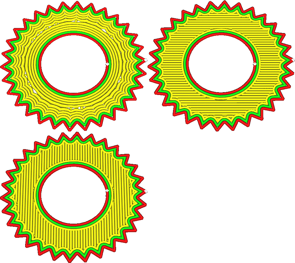
The concentric pattern tends to adhere much better to the build plate than other patterns, because the tension in the lines when they are shrinking is spread out in all directions. This prevents warping and improves the reliability of the print. Other patterns contract all in one direction.
When printing with a raft, using the lines pattern tends to give a slightly stronger part. The lines are then also oriented such that they bridge the gaps between the raft lines well, creating a smoother bottom side.
¶ Support Structure
¶ Support Type
With this setting you can choose which algorithm to use to construct the support structures. These constructions have vastly different properties, so choosing an algorithm will have a big influence in how well your print gets supported. There are three options available.
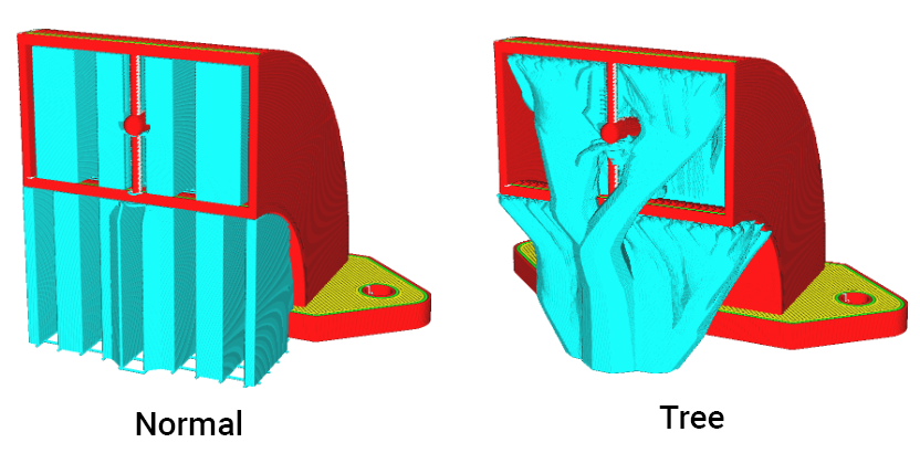
Normal
This is a traditional support structure, the one that most people are used to. The structure is generated underneath the overhanging areas, and typically filled with a pattern that directly supports the overhanging areas. From there it is dropped straight down until it reaches the build plate or a part of the model that supports it.
The normal support construction has been the default for most of 3D printing processes, and works similarly in all slicers. This is the golden standard, and not without reason:
-
Due to its sturdy structure, with big contact areas on the model and build plate, it is very reliable. It is very forgiving with bad settings or a badly tuned printer.
-
Because the shape is simple, it is quick to slice.
-
The straight support structure is easy to customise for a user, since it's immediately clear which borders are going to be supported and which are not.
The most important downsides arise from the same properties:
-
Due to the large contact areas, the support is often hard to remove and can leave significant scars on the surface where it touched.
-
Although it is stable, it can use a lot of material and take a lot of time to print. This can be counteracted to an extent by using conical support.
Tree
With tree support, the support structure will start out small on the build plate, and will grow branches towards the parts of the print that need supporting.
Tree support can avoid obstacles when growing towards the overhang areas, since the support doesn't need to drop straight down. If at all possible, the support will rest only on the build plate, to prevent scarring of the surface that the support rests on. If no path exists from the build plate to the overhang, it will rest on a surface that is as close to the overhang as possible, to minimise material usage. The branches of tree support are limited by the Tree Support Branch Angle so that they don't produce too steep an overhang themselves. This limits their ability to grow around obstacles.
-
Tree support often uses way less material than ordinary support. Between 25% and 50% of the material usage is common. This saves a lot of time and reduces the cost of the print.
-
Because of its small contact area, overhang tends to look better when using tree support.
-
Also because of the small contact area, the support will be easier to remove.
-
It leaves fewer scars on the surface than normal support, due to being able to reach around the model from the build plate towards the overhang.
The main disadvantages are however:
-
It takes significantly longer to slice than normal support. Patience will be necessary, especially with tall models.
-
There are lots of interruptions in the flow when the smallest branches are printed, making tree support unsuitable to print using materials that are hard to extrude, such as PVA or flexible materials.
-
Tree support tends to place too few branches to support flat, sloped overhangs.
Tree support is hollow by default. Due to its jagged shape, the tree support is normally quite sturdy. The Support Density can be used to give the support more structural strength.
No Support
No support is generated for the model. With this option selected, the overhanging parts of the model may collapse during printing.
¶ Support Pattern
With this setting you can choose the pattern that will be used to fill the volume of the support structure. Different patterns have different strengths and weaknesses.

Line
The lines pattern draws straight lines. The lines are oriented such that they are never perpendicular to the skin lines it needs to support (by default).
-
Easiest to remove from the model of all patterns. This is very useful if there is an overhang area that is close to the build plate. A knife can be used to cut away the remnants if necessary.
-
Provides the best overhang quality of all patterns together with Zigzag. The lines are very close together and oriented such that they are not perpendicular to the skin.
-
Tends to be unstable, since the lines are prone to topple over.
Grid
The grid pattern draws two sets of straight lines perpendicular to each other. They overlap, forming a pattern of squares. By default, one perimeter is drawn around this pattern.
-
Very sturdy and reliably.
-
Provides a mediocre overhang quality, since the lines are fairly far apart.
-
Can be hard to remove, since the support will not flex much.
Triangles
The triangles pattern draws three sets of straight lines in 60 degree angles with one another, forming a pattern of equilateral triangles. By default, one perimeter is drawn around this pattern.
- The sturdiest of all support patterns.
- Provides bad overhang quality, since the lines are very far apart.
- Can be hard to remove, since the support will not flex at all in any direction.
Concentric
The concentric pattern causes the support to consist of concentric rings spaced evenly from the outside inwards.
- Lines are close together, providing good support of the overhang areas for a smooth surface.
- Fairly sturdy, since the loops individually have a large width to stand on.
- Easy to remove, since the support structure will bend inwards easily.
- Often ends up parallel to the walls it needs to support. This leads to worse overhang quality, since some walls don't get supported at all.
Zig Zag
The zigzag pattern is like the lines pattern, but the lines are connected on the ends.
- Fairly sturdy, greatly increasing reliability.
- Provides the best overhang quality of all patterns together with Lines. The lines are very close together and oriented such that they are not perpendicular to the skin.
- Easy to remove. The support structure bends inwards, and when pulling on it, the support will pull off in strips.
- Almost always draws the support in a single line, minimising the need for retractions or travel moves.
Cross
The cross pattern draws a fractional pattern throughout the volume with cross-like shapes in it.
- Easiest to bend of all patterns, since there are no long straight lines in this pattern.
- Almost always draws the support in a single line, minimising the need for retractions or travel moves.
Gyroid
The gyroid pattern is a wavy one, with a curve wiggling back and forth. The curve varies across the layers.
- Fairly sturdy pattern, increasing reliability.
- When printing with soluble support materials, this allows the solvent (water, ethanol or otherwise) to protrude to all the innards of the support structure, even if there is a brim underneath. This allows it to dissolve the support faster.
- Supports all lines in the overhang evenly, regardless of their directions.
¶ Support Wall Line Count
This setting adds a number of walls around the perimeter of the support.

The extra walls add strength to the support, reducing the chance that they topple over. It also allows the support to better support the very edges of the overhang area. For models with sharp corners, these edges tend to be problematic because lines end in mid-air there. This setting can make them end on a support line instead.
However the extra walls also take more time to print, use more material and make the support harder to remove from the object afterwards. When working with soluble support materials, the extra walls cause the support to take longer to dissolve because the solvent cannot enter the support structure from the side any more.
¶ Connect Support ZigZags
If the zig-zag pattern is chosen for the Support Pattern setting, this setting makes the endpoints of the support pattern connect back towards itself, making the support stronger, but harder to remove and causes it to leave more of a scar.
¶ Support Density
This setting defines the rate at which the support structures are filled with material. At great infill rates, the support lines will be placed very close together. At low infill rates, the lines will be placed further apart.

Here are some of the effects that need to be weighed off:
- Since the distance between the support lines is smaller, the surface resting on top of this support will sag less.
- The support will be stronger, improving reliability of the print.
- It's harder to remove the support due to the increased adhesion surface.
- It will take more material to print the support.
- The print will take longer to complete.
¶ Support Line Distance
This setting defines the distance between two adjacent lines in the support pattern. This way of adjusting the density of support may be more intuitive than adjusting Support Density, since it directly adjusts the distance that the supported lines must bridge.
¶ Initial Layer Support Line Distance
The density of the support's first layer can be adjusted separately from the density of the rest of the support. This setting configures the distance between two adjacent lines where the support rests on the build plate. It is useful to improve the adhesion between support and the build plate, making it stick better.
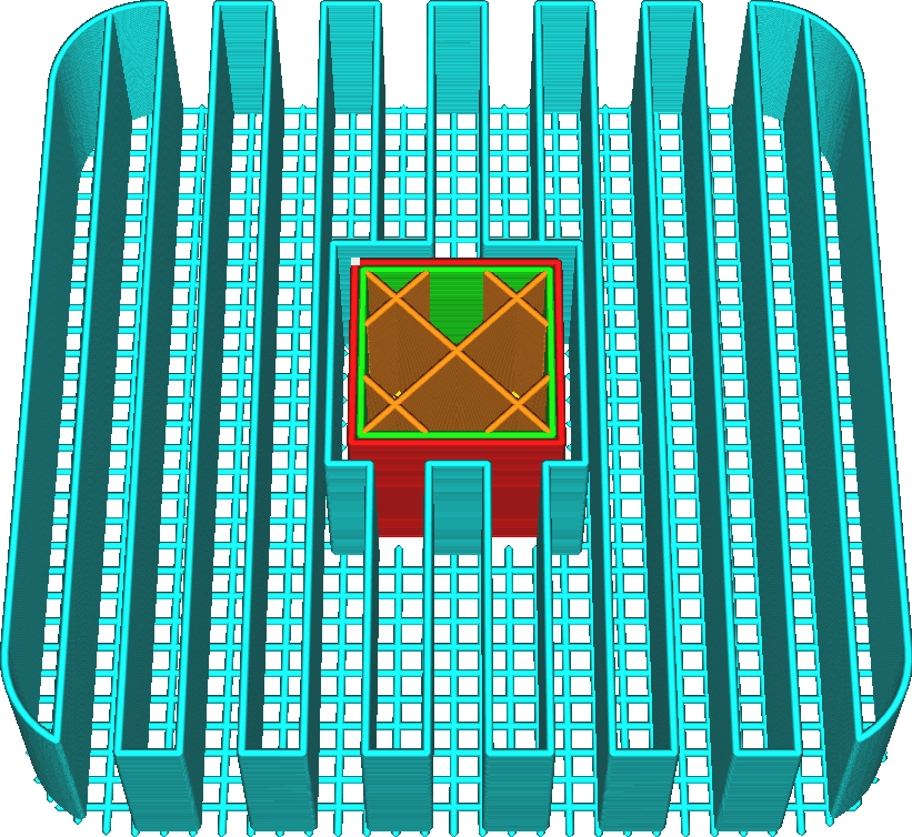
Since this setting only affects the first layer, so it doesn't significantly affect the strength of the support nor the time and material cost. It also doesn't affect the quality of overhangs.
It is a good idea to make this setting a multiple of the line distance of the main body of support. This way, the lines of support will match up with the lines on the first layer, allowing them to rest on the first layer instead of floating in air.
¶ Support Placement
This setting allows you to choose where support can be placed on top of. You can choose to place support everywhere it may need, or place support only when it touches the build plate.

Everywhere
Placing support everywhere is more reliable for the support. All overhangs that would sag are supported properly. However, the support may rest on top of the model as well, leaving a scar where it touches. This reduces the visual quality and the smoothness of the model's surface after the support is removed.
Touching Buildplate
Instead, placing support only on the build plate prevents support from resting on the model. This may leave some parts of your model unsupported, though.
As a trick when using support on the build plate only, try enabling conical support and giving the Conical Support Angle a negative value. This allows the support to grow around the model and still support most of the mesh without resting on the model. Alternatively, try tree support.
¶ Support Overhang Angle
The overhang angle in 3D printing refers to the maximum angle at which a part of the model extends outward at an angle from the vertical axis of the object being printed. The 45° rule serves as a practical guideline when dealing with overhangs in 3D printing, and it is not recommended to set the angle bigger than 50°.
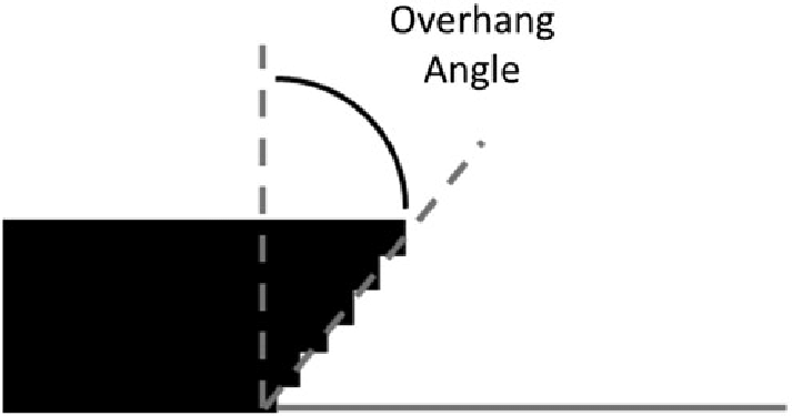
The overhang angle influences how much support material is added and where. Reducing the value of this setting generates more support. For example, at a value of 10° most of overhangs are supported, while at 90° no support material is added.
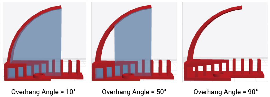
Reducing this setting makes more of the printed parts get supported, even surfaces that are steeper and won't sag much during printing. If unnecessary support is generated, it'll increase the printing time and material usage unnecessarily and also create scars where the support touched the print.
Reducing the support angle is sometimes necessary to prevent the material from sagging too much. It generally improves the dimensional accuracy of the final part and makes the overhangs look better.
Whenever working with support, it's a good idea to preview what the support looks like in the Preview stage. There you can see where it will actually generate support. Adjusting this setting can filter out unnecessary support.
¶ Support Preference
Removable
Generates supports that are easy to remove without scarring the model.
Reliable
Generates supports that are reliable to ensure a successful print. However, the adhesion between model and supports is increased, making the the supports hard to remove. Thus, it applies best to easily breaking or soluble materials.
0 Gap
There is no gap between the support and the model.This can improve print success rates, but may result in some loss of underside print quality (For breakaway and soluble materials).
¶ Support Z Distance
This setting indicates the vertical clearance that must be kept between the support and the model, both at the top of the support and the bottom. This setting is the most influential factor in how well the support adheres to the model.

-
If this setting is reduced, the support will stick better to the model. This makes overhangs look better since they are not allowed to sag as much. It will also improve the stability of the support, because it is firmly positioned on top of the model at the bottom side of the support.
-
If this setting is increased, the support will be easier to remove. It won't leave as much of a scar on the surface where the support was supporting the model. On the other hand, the model won't be supported as well. This reduces the surface quality of the overhangs.
As a general rule, the better the support material sticks to the build material, the greater this setting must be. If you're using a different material to print the support, the Z distance can be lowered considerably since two different materials tend to separate more easily after solidifying. If you're using a material with good layer bonding, the setting must be increased a bit. Printing hotter or with thicker lines also increases bonding, and thus also require increasing this setting.
¶ Support Top Distance
This setting configures how much distance is kept between the top of the support and the overhung surface of the model.

The support top distance is the most influential factor in how well the support adheres to the model where the model rests on the support. Increasing the distance makes it easier to remove the support after printing, since it won't adhere well to the printed object. However it will also make the overhang look worse, since it's allowed to sag a few more layers down before resting on the support.
¶ Support Bottom Distance
¶ Support X/Y Distance
This indicates how much distance must be kept horizontally between the support and the model.
The horizontal distance is meant to prevent the support from hitting the model, where it would leave a scar on the surface. However, this also creates a larger distance between the model and the support structure where the overhang is, leaving some overhangs unsupported.

¶ Support Distance Priority
The settings for Z distance and XY distance typically differ. When generating support structures, Luban cannot adhere to both of these rules simultaneously. The Support Distance Priority setting determines whether XY or Z is more important.
¶ X/Y overrides Z and Z overrides X/Y
If X/Y overrides Z is selected, the X/Y distance between the model and the support structure will remain constant, while Z distance might change across different layers.
Conversely, if Z overrides X/Y is given priority, then Z distance will be kept constant, while the X/Y distance might change acorss different layers. In such case, the X/Y distance only gets influence over the print in locations where the Z distance does not come into play, not at the top of the support, but only at the sides.
The image below illustrates the effect when XY overrides Z, and when Z overrides XY.

¶ Minimum Support X/Y Distance
When Z distance takes priority over X/Y distance, to satisfy the Z distance setting, the X/Y distance might become smaller than the Support X/Y Distance setting, and end up too close to the model. To ensure that the support does not collide with the model, Luban introduces Minimum Support X/Y Distance. This setting deifnes a minimum X/Y distance that must be held constant regardless of the Z distance. When conflicts the Z distance, it overrides the Z distance.

- Increasing this setting reduces the chance that the support hits the model on the side, leaving a scar where it's unnecessary. It also makes the support easier to remove. However, increasing this setting also makes the overhang sag more, reducing its surface quality.
¶ Support Stair Step Height
When the support placement type "Everywhere" is selected, support structures can be generated on top of the model. These structures do not necessarily follow the contours of the model smoothly. Instead, the bottom of the support structure consists of small stair-like steps. Adjusting the stair step height value affects the size of these steps. A lower value results in a smoother bottom of the support and more connections between the model and the support structure. Conversely, a higher value makes it easier to remove the support afterward.
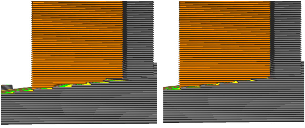
¶ Support Stair Step Maximum Width
It determines the maximum width of the stair steps. The support structure normally follows the model with the given stair step height value. However, if that exceeds the maximum width setting, it then follows the model's surface for the rest of that step.
¶ Support Stair Step Minimun Slope Angle
On shallow slopes, the stair steps at the bottom can be very wide, increasing the need for bridging. This setting controls the minimum slope angle for which to apply stair steps. Higher values lead to sturdier support, but these structures can be harder to remove. Lower values reduce scarring and are easier to remove, but may cause unstable support structures.
¶ Support Join Distance
When multiple pieces of support are adjacent to one another, they can be joined together, forming one piece of support that is much sturdier.
This setting controls the maximum distance between separate support structures in the X and Y directions. When supports are closer together than this specified distance, they will merge.

The left model has separate supports, while in the right model, the two supports have merged.
Setting a high value will cause support structures to merge sooner.
Merging support structures results in more stable support. Depending on the pattern, it can often reduce printing time and material usage. However, if this value is increased too much, it may create a large block of unnecessary support that uses more material and becomes harder to remove.
¶ Minimum Support Area
This setting determines the minimum footprint area that supports must cover before being disregarded. By default, supports are printed for all necessary areas. However, when thin support structures appear in undesired locations, they can be filtered out. Thin supports are often unstable and should generally be avoided. With this setting enabled, some parts of the model may not receive support, resulting in decreased overhang quality.
To avoid thin support pillars, you can use Support Horizontal Expansion or Join Distance to increase the support area, or apply support blockers to eliminate unnecessary thin support sections.
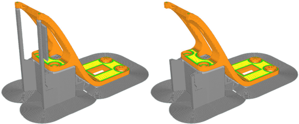
The model on the left shows all supports in place by default. In contrast, the model on the right applies a minimum support area of 3 mm², ignoring the thin overhang regions.
¶ Support Structure Fine-tuning
¶ Enable Support Interface
A "support interface" is an intermediary structure in between the normal support and the model. This structure can adjust the properties of how support interfaces with the model without affecting the majority of the support much.
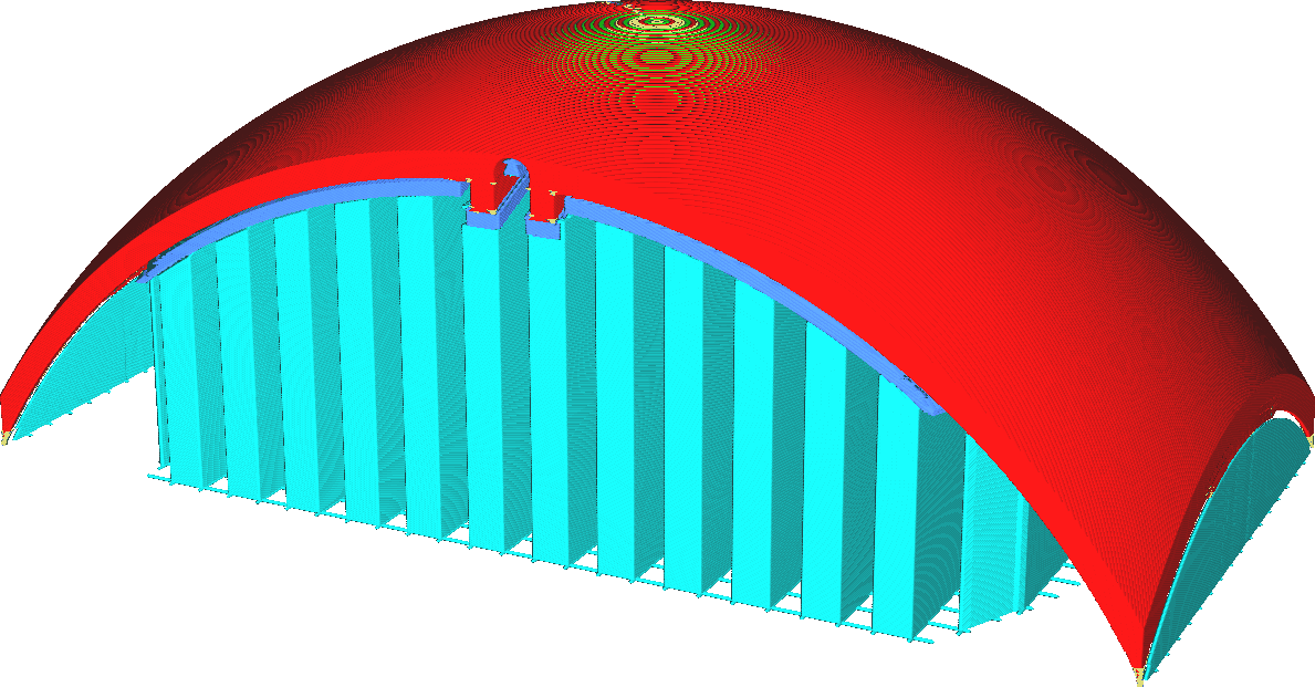
By default the interface layers are denser than the normal support. This achieves a better overhang surface without needing all that much extra material and printing time. However, it will be harder to remove the support.
The support interface can also be printed with a different extruder than the rest of the support. Therefore, it is possible to print the support with cheaper or faster material, then print the other parts with the fancier material.
¶ Enable Support Roof
The support roof is an intermediary structure between the support and the model where the model rests on the support. It can be used to provide better support for the model without significantly impacting printing time. The support roof is typically printed more densely or slower.
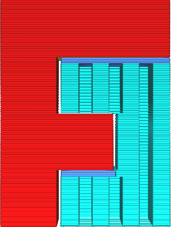
By default the support roof is denser than the normal support. This provides a better quality overhang, since the model doesn't need to bridge large distances. However, it will be much harder to remove the support.
¶ Enable Support Floor
The support floor is an intermediary structure between the support and the model where the support rests on the model. It can be used to provide a more stable base for the support or to make the support easier to remove from the print, leaving fewer scars.
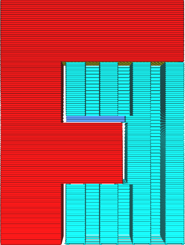
The support floor is not generated where the support rests on the build plate.
The support floor can be printed more slowly to get more stable support, or using a different material that is easier to remove from the model. This way, not all of the support needs to be printed with this material or these settings, which can save a lot of printing time.
¶ Support Horizontal Expansion
This setting causes the support to become slightly wider, expanding horizontally in every direction.
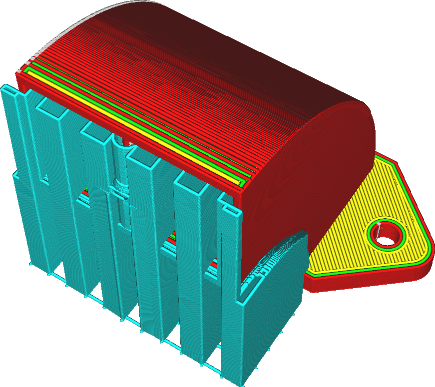
This setting has multiple uses, depending on the material used for support and the type of model that needs supporting:
-
Increasing this setting will make support wider and thus sturdier. This is useful for tall models with small areas of overhang, since the overhang would otherwise be supported with a very tall, thin pillar of support. With some horizontal expansion, it becomes a very tall but slightly wider pillar of support.
-
Increasing this setting also functions as a safety measure to make sure that support areas have a certain minimum area. This is necessary for materials that are hard to extrude, such as PVA.
-
Reducing this setting will reduce material usage and printing time for support. Increasing it will increase the required material and printing time, of course. See also the conical support feature, which reduces the width of support without compromising the area that the support supports.
-
Setting it to a negative value can also remove thin pillars of support completely.
¶ Use Towers
Small areas of overhanging surfaces produce small pillars of support. These pillars are prone to topple over. Instead of those small pillars, Luban can generate specialised towers that are wider and more sturdy, to prevent the support from falling over.

Overhang areas smaller than the Minimum Tower-Supported Diameter will get supported by such a tower instead of the normal support structure. These towers are wider so that they won't topple over. Near the top of the tower, the tower will get more narrow towards the width of the overhanging surface that actually needs support.
These towers have a larger diameter than the region they support. This makes the towers more stable than regular support, but also requires more material, printing time and space on your build plate.
¶ Tower Diameter
Some overhanging parts of the model are very small. The support that would be generated would topple over easily. Instead, Luban generates towers for these pieces that are wider, so they won't topple over.
This setting configures how wide those towers are.
Wider towers take slightly longer to print and consume more material, but they also make the support more sturdy which ultimately improves the reliability of the print.
¶ Maximum Tower-Supported Diameter
This setting is a threshold for the diameter of a piece of overhang to choose between normal support and support towers. If the piece is thinner than this threshold, it'll get supported by a support tower. If it is wider than this threshold, it'll get supported by the ordinary support structures.
If a very thin strip of overhang needs support, normal support would topple over. Instead, a more sturdy tower is generated.
Increasing this setting will cause towers to be generated more frequently. This increases the reliability of the support, but also requires slightly more material and printing time.
¶ Tower Roof Angle
Support towers get a pointy top, which transitions the wider pillar of the tower towards the narrow area of overhang that actually needs to get supported.
-
A higher value makes the support towers have a very pointy roof. This causes the tower to start reducing its width a bit lower down already, which reduces the stability of the tower but saves on some material and printing time.
-
A lower value makes the support towers have a flatter roof.
¶ Enable Support Brim
When the support brim is activated, an additional brim will be drawn inside the support area on the first layer.
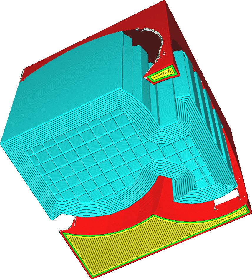
The support brim is drawn towards the inside, unlike the ordinary brim. If the Build Plate Adhesion Type is set to Brim, another brim will also be drawn around the support.
The purpose of this brim is to give the support more surface area where it can adhere to the build plate. This can also be achieved by adjusting the Initial Layer Support Line Distance, but with this feature the adhesion will be concentrated around the edge of the support area, where it is more effective to prevent warping.
A support brim can significantly make the support stronger. It will also slightly increase the printing duration and material cost, but since it's only on the first layer this is very minimal.
¶ Support Brim Width
This setting adjusts the width of the support brim. With a wider support brim, more contours will be drawn inside the support area to give better adhesion.

A wider brim will increase the adhesion of the support to the build plate and reduce warping of support. As a result, the support will stand more sturdily, which improves reliability of the print.
¶ Support Brim Line Count
This setting adjusts the number of contours that will be drawn inside the support area for the support brim. With more lines, the brim will become wider.
More brim lines will increase the adhesion of the support to the build plate and reduce warping of support. As a result, the support will stand more sturdily, which improves reliability of the print.
¶ Fan Speed Override
This setting causes the fans on the toolhead to spin at a different rate while the skin that rests on top of support is printed. The speed at which the fans spin is determined by the Supported Skin Fan Speed setting.
Where the model has overhangs, you'll want that to be supported. The part that gets supported should rest on the support but should not stick to it. If the material is too hot, it'll sag a lot and really lean into the support. This makes it stick too much to the support, and reduces the accuracy of the overhang as well. With this setting, you can increase the fan speed for parts where the model is resting on the support. This cools down the material faster, which makes the model stick less to the support and improves the quality of overhangs.
¶ Gradual Support Infill Steps
Gradual support reduces the amount of support material used, by reducing the support density in the lower layers. This saves on printing time and material, while not reducing the overhang quality much. The primary purpose of support is to support overhanging areas. This feature focuses the support to that purpose only.
This setting indicates in how many steps the support density gets reduced. At every step, the support's density is halved. For example, starting at a density of 20% and two gradual support steps, the support density of the lower parts will be 10% and 5% respectively.
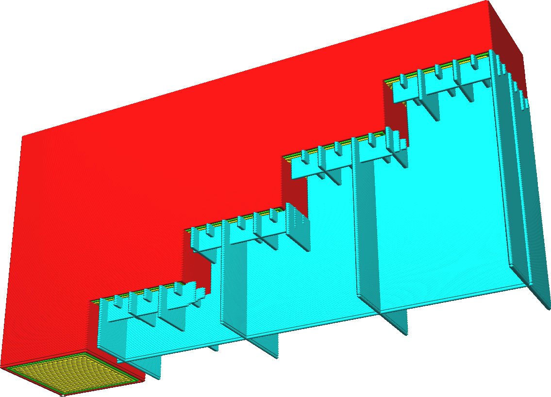
Increasing the number of steps cause the density to be halved more and more, resulting in lower density support. This saves a lot of material and printing time, but will make the support weaker.
Some of the support will be floating in mid-air. However, in practice with most support patterns this will repair itself quickly as the layers can build up properly even on weakened lower layers. The intent of the Gradual Support Infill Step Height is to allow sufficient time for the layers to repair themselves before the next gradual support step is piled on top.
This setting is best combined with at least one Support Wall Line. This gives the support lines something to hang on to, rather than being suspended in mid-air.
¶ Initial Layer Adhesion
¶ Build Plate Adhesion Type
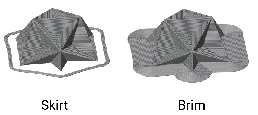
There are three types of build plate adhesion: skirt, brim and raft.

You can also disable adhesion by setting the Build Plate Adhesion Type to None.
-
Skirt
A skirt is single line or multiple lines encircling the base of your print. It will not directly contribute anything to build plate adhesion. However if you don't want to use the other adhesion methods, this method still serves two functions.
It causes your nozzle to prime before starting the printing of your actual model, to make sure that the material is properly flowing.
It allows you to see whether or not your build plate is properly levelled. -
Brim
A brim is a single layer flat area around the base of your model. Its purpose is to keep the edges of your print down and make the contact area between your print and the build plate bigger.The bigger surface area allows your print to stick better to the build plate. This is useful for pretty much any print larger than a few centimetres.
This brim will also keep the edges of your print down. Materials that shrink a lot when cooling down (like ABS) tend to warp a lot while printing. Having a brim with sufficient width can keep the corners in place, preventing this warping.
-
Raft
A raft is a thick plate between the model and the build plate. This raft shields your print from the heat of the build plate. It will also have a lot of surface area to stick to the build plate with. The print gets put on top of this raft, where it may stick much better. Be careful with thin prints though, since it may be hard to remove the raft without damaging the print.
¶ Skirt Line Count
This setting configures the number of contours to draw around the print, for the skirt.
¶ Skirt Distance
Skirt Distance is the distance of the closest line of the skirt to the model.
By keeping enough distance, the skirt won't attach to the model, reducing the elephant's feet effect.
¶ Skirt/Brim Minimum Length
The skirt/brim length refers to the total length of extrusion required to prime the nozzle when printing the skirt or brim.
The value of this setting should be set such that the volume extruded by this minimal length is just enough to prime the nozzle before a print.
¶ Brim Line Count
This setting controls how many perimeters are being drawn around the base of your print, for the brim.

More brim lines will improve adhesion to the build plate, by increasing the surface area of your print. However, it will reduce the effective print area.
¶ Initial Layer Line Width Factor
This makes the lines in the initial layer wider or thinner by a certain ratio.
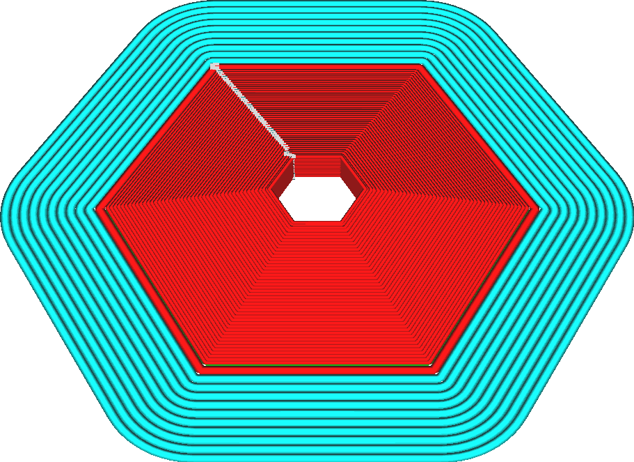
The goal of this setting is to improve adhesion to the build plate. In order to print wider lines, the nozzle has to extrude more material and that material has to flow wider outward. This causes the nozzle to press the material harder on the build plate, which increases adhesion between the filament and the build plate.
Configuring this setting will have two effects:
-
Not only will the lines be wider or thinner, but they will also be farther apart or closer together by the same factor, so it would not produce overextrusion or underextrusion.
-
This setting affects all line widths, skin, walls, adhesion, support, and the prime tower on the first layer. They will be made wider or thinner by the same ratio.
¶ Initial Layer Speed
This setting adjusts the speed at which the initial layer of the model is formed.
Reducing the initial layer speed will improve the adhesion between the model and the build plate. This is because the material stays hotter for a longer time and can then flow out further, which can increase the adhesion.
For the initial layer, the printing speed can be adjusted separately from the travel speed. This setting can adjust the speed of the brim and skirt by default, however, it does not influence the speed of the base layer of the raft.
¶ Initial Layer Print Speed
This setting controls the speed when printing the initial layer of the model.
Reducing the initial layer printing speed will improve the adhesion between the model and the build plate. This is because the material stays hotter for a longer time and can then flow out further. This reduces the internal stresses in the material and increases the contact area, both of which increase the adhesion.
Adjusting this setting will adjust the speed of the extrusion moves in the first layer, but not the travel moves. For that, adjust the Initial Layer Travel Speed setting. By default, this setting influences the Skirt/Brim Speed setting. The speed of the raft base layer is not affected.
¶ Initial Layer Travel Speed
This setting adjusts the speed of the travel moves during the printing of the first layer.
The travel speed needs to be lower during the first layer than during the rest of the print, because there is a greater chance for the nozzle to rip the print off the build plate.
¶ Skirt/Brim Speed
This setting adjusts the printing speed of the skirt or the brim separately from the rest of the print.
The skirt or brim is usually printed rather slowly, in order to make it stick better to the build plate, but takes more time to print.
Even though the skirt and brim are printed on the first layer, this setting overrides the Initial Layer Print Speed.
¶ Initial Layer Acceleration
This setting controls how fast the nozzle accelerates into different directions while printing the first layer. The acceleration during the first layer can be set to a different rate than the rest of the print.
While the walls, platform adhesion, bottoms, support and infill may all have different rates of acceleration, during the first layer they will be made the same. The initial layer acceleration rate will override the individual structures' acceleration rates.The Skirt/Brim Acceleration setting overrides the initial layer print acceleration as well.
¶ Initial Layer Print Acceleration
This setting controls how fast the nozzle accelerates into different directions while extruding in the first layer.
-
Printing at high rates of acceleration can cause vibrations of the printer. In particular, these vibrations can make the build plate shake up and down, which is detrimental to the adhesion of the print on the build plate.
-
Reducing the acceleration for the first layer can reduce vibrations during this critical part of the printing process. It will take more time to print though, and reducing the acceleration rates too much can cause inconsistent extrusion in the corners which is also detrimental to build plate adhesion.
¶ Initial Layer Travel Acceleration
This setting controls how fast the nozzle accelerates into different directions while travelling across the build plate during the first layer.
-
Printing at high rates of acceleration can cause vibrations of the printer. In particular, these vibrations can make the build plate shake up and down, which can cause the nozzle to hit the build plate and damage the printer. The vibrations can also continue on after the travel move and affect extrusion, which is detrimental to the adhesion between the model and the build plate.
-
Reducing the acceleration of travel moves during the first layer compared to other layers can prevent these effects. However to save time, the acceleration during travelling in the first layer can still be higher than during the extrusion moves of the first layer, because vibrations are usually only a problem while extruding.
The acceleration during travels on the first layer can be set to a different rate from the travel moves in the rest of the print or the extrusion moves of the first layer.
¶ Skirt/Brim Acceleration
This setting controls how fast the nozzle accelerates into different directions while printing the skirt or the brim.
The brim is crucial for bed adhesion, so reducing the acceleration rates during the printing of the brim can reduce vibrations while the brim is printed and then make the adhesion of the brim to the build plate better, increasing the effectiveness of the brim at a minor printing time cost.
The effect of acceleration on the brim and skirt is usually extremely small though, because the brim and skirt consist of lines with smooth curves. The acceleration is often completely taken over by the Skirt/Brim Jerk setting.
The acceleration during the skirt or the brim can be set to a different rate than the rest of the print. This setting overrides the Initial Layer Print Acceleration setting. The Brim or skirt will be printed using the acceleration determined with this setting, not the setting for the initial layer in general.
¶ Number of Slower Layers
The initial layer is not the only layer that gets printed slower. This setting configures how many layers get printed slower. Over the course of these layers, the printing speed will gradually increase to the normal printing speed.

There are two reasons why you could want to transition to the normal printing speed over several layers:
(1) The second and third layers are still quite close to the build plate, and moving fast over them can rip the print loose pretty easily.
(2) The difference in flow rate between the initial layer printing speed and the ordinary printing speed may be so great that the large flow rate change may take some time to come into effect.
Transitioning slowly prevents underextruding at a great speed change. However, transitioning slowly will also increase the total printing time.
¶ Dual Extrusion Helper
¶ Dual Extrusion Helper Type
During dual extruder printing, the extruder being inactive may continue to ooze out material when its nozzle temperature is still high. Then, when this extruder starts printing again, the accumulated ooze beneath the nozzle may stick to the object, leading to an unsightly print. That's why we need to use dual extrusion helpers. Luban provides you with two types of dual extrusion helpers, each with its own feature.
-
Prime Tower
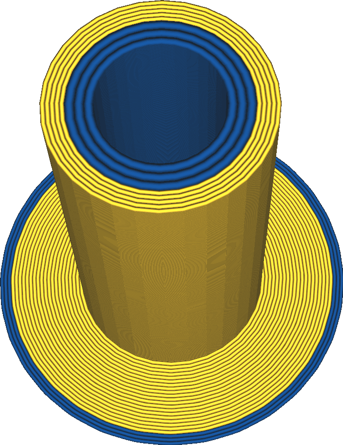
Prime tower, also called wipe tower, is an additional print that's created separately on the build plate to help the inactive extruder switch back properly.

Actually, material oozing will not only cause unsightly appearance, but also result in an empty chamber, followed by improper flow at the beginning of the print. By printing the prime tower, the stand-by extruder can wipe off any ooze from its nozzle and prime its chamber for proper mateiral flow.
The prime tower is a hollow cylinder consists of a continuous outer shell printed by one extruder and some discontinous inner walls printed by the other extruder. The continuous outer shell is necessary for maintaining the stability of the tower, although it may cause extra extruder switches for some prints. The inner walls are not printed when there is no extruder switch.
The disadvantages of the prime tower are that it takes some extra time to print and occupies some space on the build plate.
-
Ooze Shield
Ooze shield is a one-layer wide wall around the object that catches ooze during dual extruder printing. The ooze shield is thin enough to break or cut easily, and keeps its distance from your model so that it can be removed without scarring the surface.
The ooze shield will print up to the height of the highest extruder switch. Above that height,printing an ooze shield is unnecessary since no nozzle will be moved into the print after being on stand-by mode.

¶ Prime Tower Minimum Volume
Prime Tower Minimum Volume refers to the minimum amount of material the extruder must purge before switching back.

Setting the Prime Tower Minimum Volume too high is relatively harmless, but makes the printing time longer and wastes more material. The volume will be limited by the Prime Tower Size.
¶ Wipe Inactive Nozzle on Prime Tower
If this parameter is activated, the printer will wipe off the previous nozzle after priming the next one in the prime tower.
The order of events will be as follows if this parameter is enabled:
(1)The printer switches to the new Extruder A.
(2)Extruder A is primed by printing the prime tower.
(3)Extruder B that was active before switch is wiped on the prime tower.
(4)The printer continues printing the model with Extruder A.
With this setting enabled, an extruder will wipe its nozzle right after being switched off.
¶ Prime Tower Brim
Prime Tower Brim is an additional brim, similar to the brim option in the Build Plate Adhesion Type. When activated, an additional brim will be printed around the prime tower. This brim is a flat disc around the prime tower of just one layer that improves the adhesion of the prime tower to the build plate.
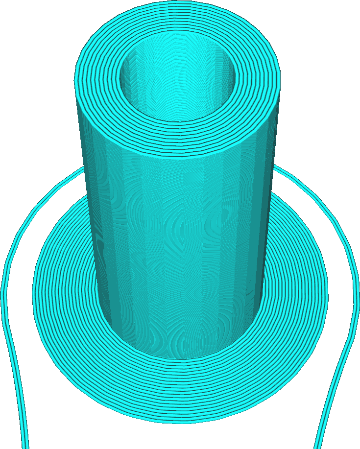
Enabling the prime tower brim will give the prime tower more surface area to connect to the build plate. Because the prime tower can get pretty tall and slim, it may topple over for very tall prints. This prime tower brim is meant to prevent that at a small cost of printing time, material and space on the build plate.
¶ Generate Interlocking Structure
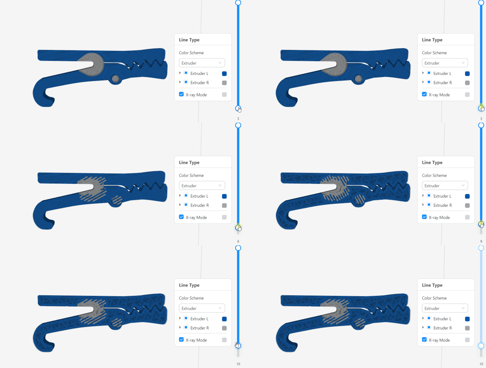
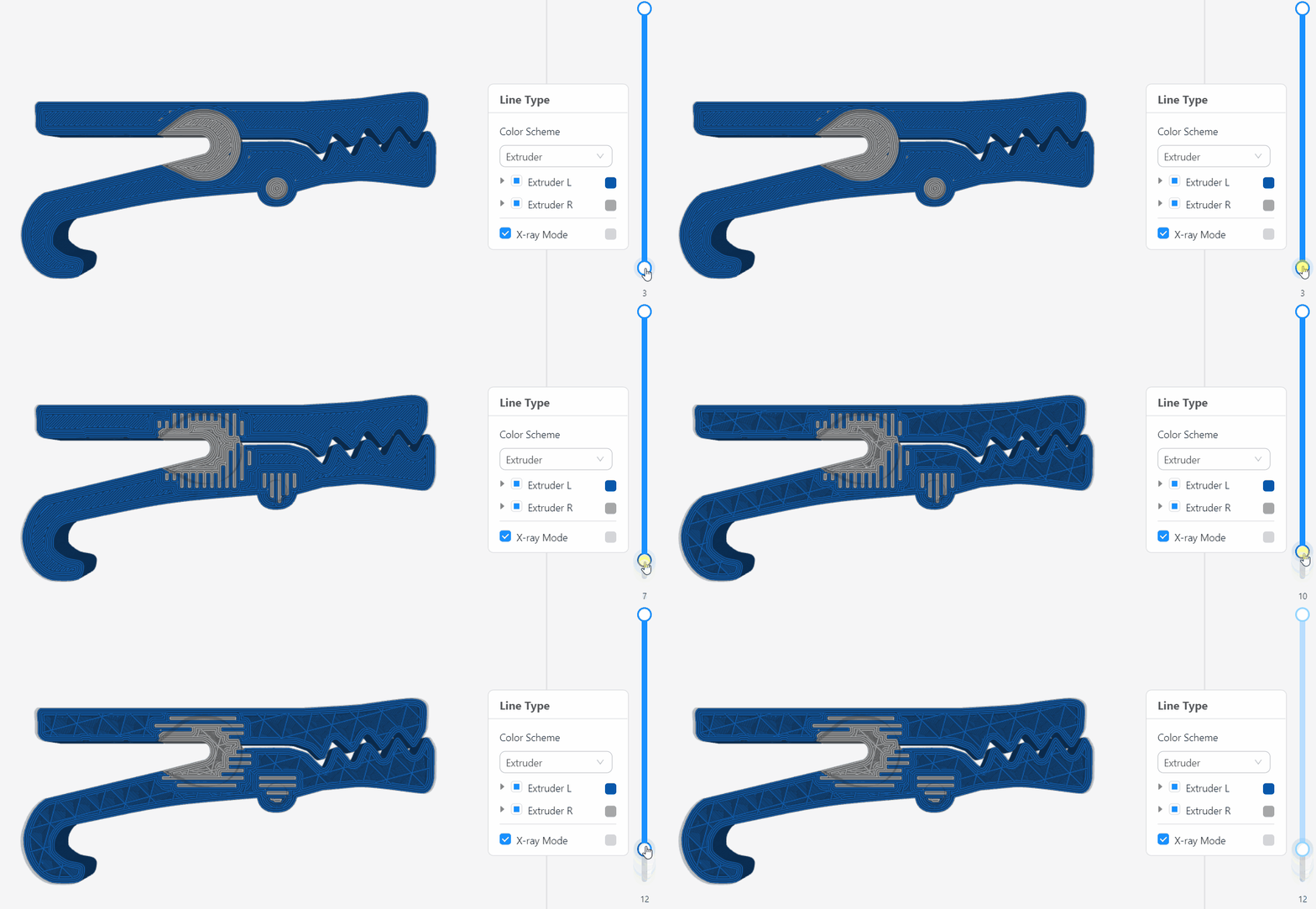
To truly enable unrestricted multi-material printing, Luban has introduced the interlocking structure, which detects the presence of two unlike, unbondable materials and generates a mechanical interlocking structure. With this feature, you can make the most use of the characteristics of the two different materials.

The idea behind interlocking structures is Luban will generate interlocking beam structures at the location where two models touch. As you can see in the image, it is much like overlaying two different infill patterns. This improves the adhesion between the models, especially if the models were printed in different materials.
¶ Interlocking Beam Width
The width of the interlocking structure beams.
It should be set as a multiple of the Outer Wall Line Width.
¶ Interlocking Structure Orientation
The angle between the interlocking structure beams.
¶ Interlocking Beam Layer Count
The height of the beams of the interlocking structure, measured in number of layers. Less layers is stronger, but more prone to defects.
¶ Interlocking Depth
The distance from the boundary between models to generate interlocking structure, measured in cells. Too few cells will result in poor adhesion.
¶ Interlocking Boundary/Avoidance
The distance from the outside of a model where interlocking structures will not be generated, measured in cells.
¶ Path Optimization
¶ Z Seam Alignment
This setting allows you to choose where the seam of each contour is placed. Several options are available that give great control over where the seam gets placed to minimise its impact or to allow you to remove the seam more easily in post-processing.
The seam is where the contour starts and ends printing in a layer. With this setting the visibility of the seam can be minimised by hiding it somewhere or spreading it around.

-
User specified
This option allows you to choose a location manually. The seam will be placed in the corner that is closest to the chosen location. This will usually line up the seams very closely together, which allows you to cut them away easily. It also allows fine-grained control over where the seam should be.
By default, a location in the back of the printer is chosen.
-
Shortest
This option minimizes the length of travel moves by placing the starting point closest to the position where the nozzle finishes the previous layer. Because the travel path is shorter, you'll save a small measure of time on travel moves. The seam will also be slightly smaller, because less ooze will be placed in the location where the nozzle lands on the contour.
The desired corner preference is still held by picking a corner close to where the nozzle is. Not the very closest corner is chosen, but a weighted preference is used to minimise travel moves somewhat but also use an appropriate corner for the Seam Corner Preference setting.
-
Random
A random location around the perimeter is chosen for the seam. This random location is changed in every layer, so the seam will get spread out pretty much evenly around the model. Because the seams of different layers don't line up, the seam will hardly be visible. However, the surface will look altogether slightly messier.
-
Sharpest Corner
The seam will be placed in the very sharpest corner of the whole contour, according to the corner preference chosen in the Seam Corner Preference setting. This may incur longer travel moves, but ensures that the seam is hidden or exposed maximally according to the preference set for the corners.
¶ Seam Corner Preference
With this setting you can control how the seams will be positioned relative to corners in your model.
Generally there are two options for where the seam can be placed: hidden in an inside corner, or exposed in an outside corner. Hiding the seam in an inside corner is generally preferable since the seam will hardly be visible there. But it is also possible to put it on an outside corner so that you can cut off the seam with a knife or sand it smooth with some sand paper, if some post-processing can be done on the part.
The following options are available for this setting:
-
None:
There is no preference for corners at all. The seam will be chosen to match the requirements for Z Seam Alignment best. -
Hide Seam:
This will prefer to hide the seam in an inside corner. If Z Seam Alignment is set to "Sharpest Corner", the very innermost corner is always chosen. If Z Seam Alignment is set to "Shortest", it will choose an inside corner near the position at which the nozzle finishes the previous layer. -
Expose Seam:
This will prefer to expose the seam on an outside corner. If Z Seam Alignment is set to "Sharpest Corner", the very sharpest outer corner is always chosen. If it's set to "Shortest", it will choose an outside corner near the position at which the nozzle finishes the previous layer. -
Hide or Expose Seam:
This will place a seam on a sharp corner, be it an inside corner or outside, as long as it's not on a flat wall. -
Smart Hiding:
This will place the seam on a sharp corner just like "Hide or Expose Seam", but inside corners will be more preferable than outside corners if any inside corners are available in the contour. If there are no inside corners, it will choose an outside corner.
¶ Wall Ordering
This setting determines which walls are printed first, printing them from the outside in, or from the inside out.
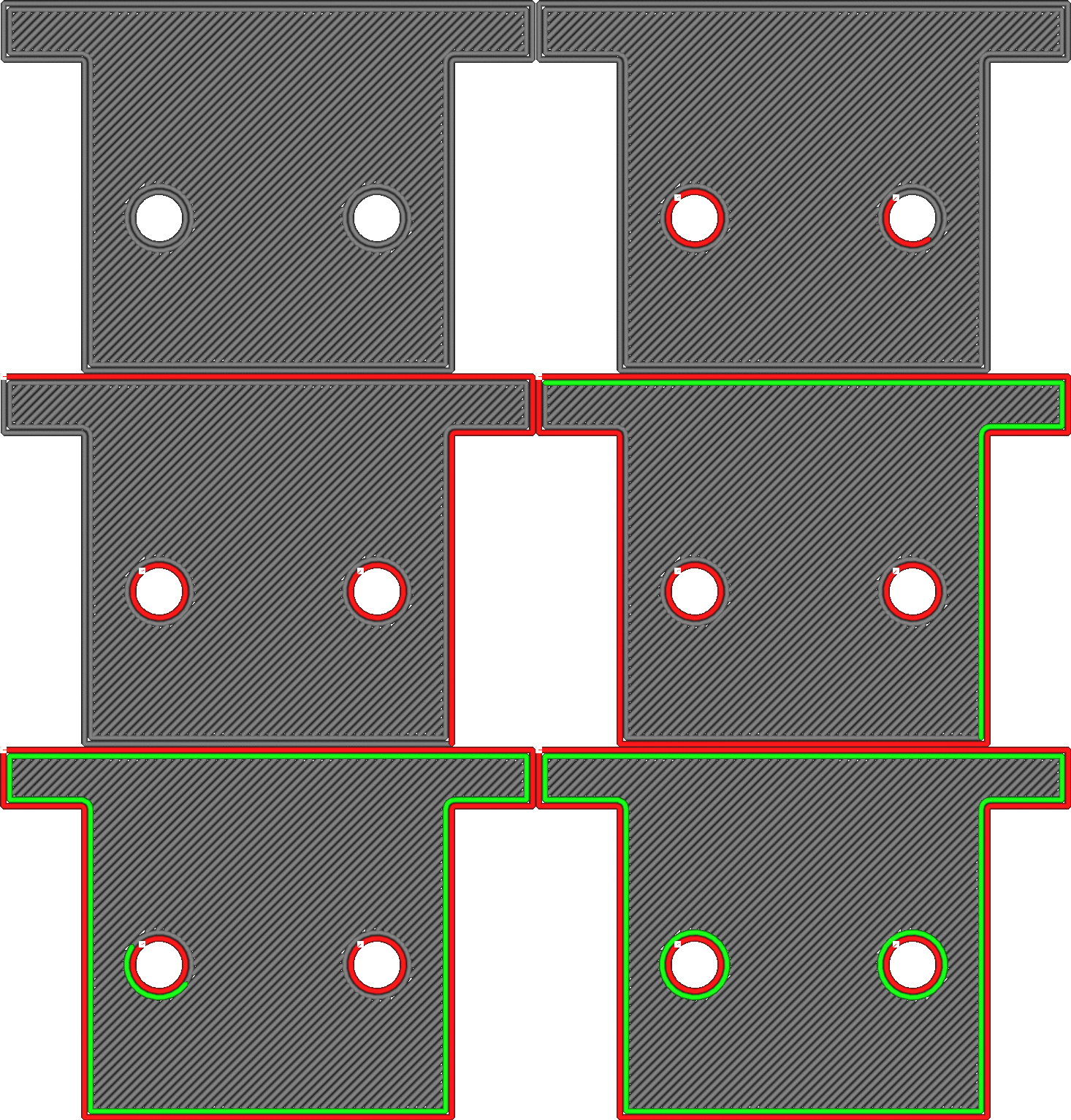
Outside to Inside
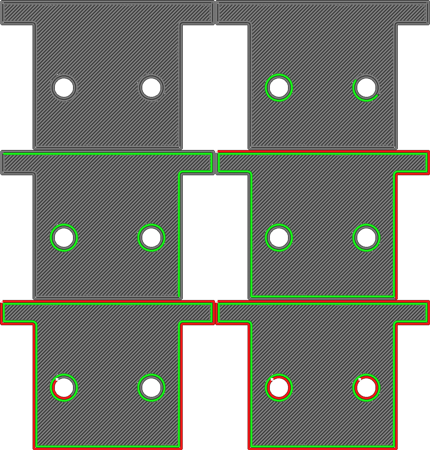
Inside to Outside
This setting has a small effect on quality as well as dimensional accuracy:
-
Printing from outside inwards will improve dimensional accuracy.
-
Printing from the inside out is better for overhang. The outer wall is further removed from the previous layer than the inner wall. When printing the outer wall first, the outer wall has nothing yet to grab on to. When the inner wall is printed first, the outer wall can attach sideways to the outer wall.
When there is an odd number of walls, the wall in the centre will always be printed last.
¶ Monotonic Top/Bottom Order
Normally, Luban orders top/bottom lines such that the travel distance between them is small. If this setting is enabled, it will order the top/bottom lines such that adjacent lines are always printed overlapping in the same direction.
Printing in a monotonic order ensures that the overlap is the same on the entire surface, thus makes the surface look more consistent and smooth.
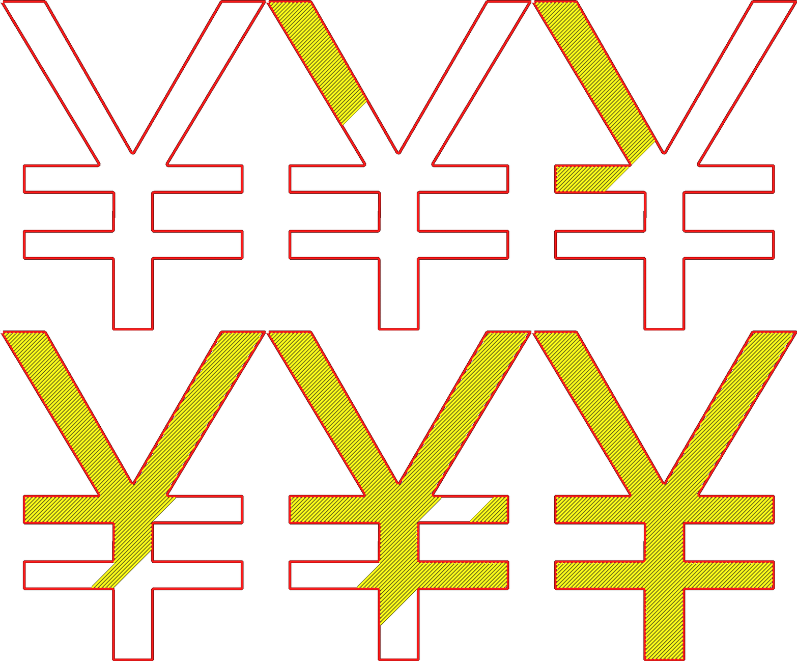
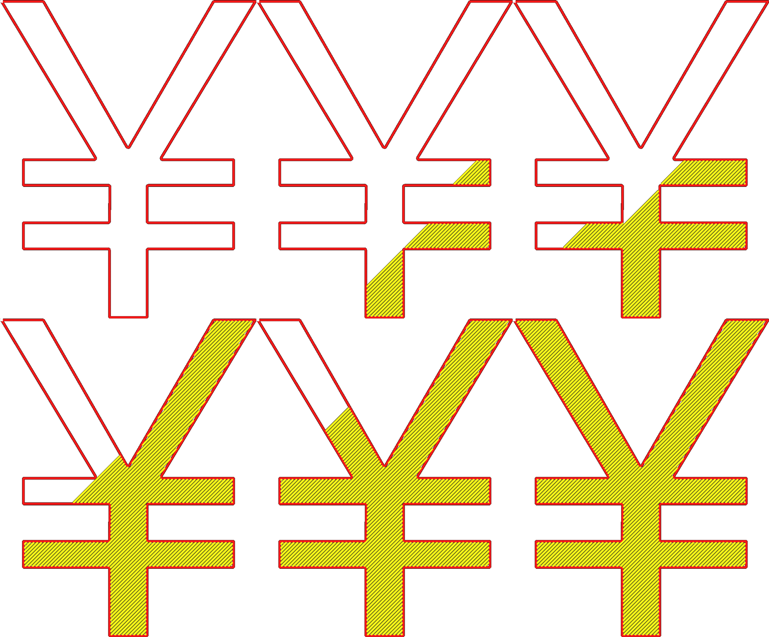
The monotonic order will slightly increase the length of travel moves, but this effect is very minimal. It only has a visual effect on the print.
To achieve a smooth surface, consider pairing this setting with setting the Combing Mode to avoid skin, and perhaps to enable Z Hops. Alternatively you could also enable ironing, but that completely overrides the usefulness of this setting. Ironing has its own monotonic option.
¶ Infill Before Walls
With this setting enabled, the infill will be printed before the walls in a layer.
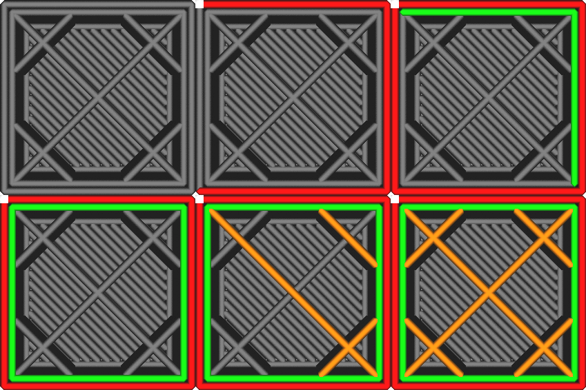
Infill Before Walls disabled
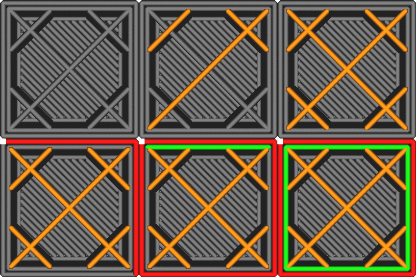
Infill Before Walls enabled
This setting is a trade-off between accuracy and strength:
-
If the walls are printed before the infill, the walls could have nothing to attach to, causing them to sag more. However, the walls will have solidified first and won't be pushed away by the infill, which prevents the infill from shining through the walls.
-
If the infill is printed before the walls, the walls will get pushed away where infill is attached to the walls, which makes the walls less accurate and can cause the infill to shine through the surface, creating a pattern visible on the outside. However the infill will hold the walls in place better while they are printed.
¶ Enable Ironing
Ironing causes the printer to do another pass over the top surface in order to make it extra smooth. This extra pass prints very small lines extremely slow.

Ironing will print a line pattern on top of the top surface of your print. This has two major beneficial effects:
-
It melts the top surface again by going over it multiple times with a hot nozzle. This is where the name "Ironing" comes from. Because the moving speed is so low and the line width is so small, the nozzle will heat up the surface significantly. The flat part of the nozzle then strokes it smooth.
-
It fills in gaps in the top surface. The ironing motion is done at the same height as the layer itself. It has less flow than a full layer, but still has some flow. In theory, this flow has nowhere to go, but in practice it will keep pressure inside the nozzle chamber. Whenever the nozzle passes over an unevenness in the surface, the material in the nozzle will flow into that gap.
However, ironing comes with some disadvantages as well:
-
If the ironing pattern has interruptions (because it has to travel to different parts), it will leave a visible line between two different ironed parts. This can sometimes be avoided by selecting a proper Ironing Pattern.
-
Sloped surfaces, or top surfaces with lots of detail, may get ironed as well, which increases the topography effect. The borders between the layers will become more pronounced. This can be prevented by enabling Iron Only Highest Layer.
¶ Monotonic Ironing Order
Normally, Luban orders ironing lines such that the travel distance between them is small. If this setting is enabled, it will order the ironing lines such that adjacent lines are always printed overlapping in the same direction.
¶ Iron Only Highest Layer
If this setting is enabled, ironing will only be applied to the very highest layer of the object. If your model has all sorts of top surfaces but only the highest is visible or only the highest needs to be smooth, then this setting enables you to save a lot of printing time.
If there are multiple objects in a print, the highest layer of every object will get ironed.
¶ Ironing Pattern
Ironing covers the top surface with a path pattern. This setting determines which pattern is used to iron the top surface.

- Zigzag
This will make the nozzle go back and forth over the surface. It works fine and reliably for most surfaces, but will cause somewhat more borders than necessary. - Concentric
This will cause the nozzle to make circles from inside to outside. This will reduce the borders to a minimum, but if the concentric rings become very small in the centre, the nozzle will be lingering too long around the same spot, and thus leaves a visible spot on the surface. Therefore, this pattern works best for surfaces that are long and thin rather than surfaces that are round or square.
¶ Ironing Line Spacing
This setting changes the space between every line of ironing. Ironing lines are normally much closer together than the normal printing lines, which is a major contributor to its effectiveness.
- Increasing the line spacing will reduce printing time.
- Reducing the line spacing will improve the top surface quality.
¶ Ironing Flow
Ironing places additional lines into the surface, technically overextruding. This setting controls how much gets extruded in this extra pass.
¶ Ironing Inset
Ironing normally doesn't smooth all the way to the outer edge. If it did, the continuous pressure in the nozzle chamber would cause the material to flow over the edge, which causes a sort of ripple effect. This setting determines how far away from the edge the ironing will keep.
¶ Ironing Speed
This setting allows you to control how fast the nozzle moves during ironing.
The ironing speed is normally significantly slower than skin printing speed. This allows the top surface lines to fuse together. However, setting a slow ironing speed will increase the total printing time quite significantly, especially when the line width of ironing is small.
Ironing behaves widely different with different materials, so you may need to set different ironing speed for different materials.
¶ Ironing Acceleration
The acceleration of ironing can be adjusted separately, to fine-tune the process.
The acceleration during ironing is normally significantly slower than the print acceleration, to ensure the layer gets a smooth surface.
¶ Small Feature Speed
Contours that are shorter than the Small Feature Max Length can be printed at a reduced speed. With this setting, you can indicate the speed at which these contours should be printed, as a factor of their normal printing speed.
Reducing the speed for these small features will make the dimensions more accurate. However it will also increase the printing time slightly. Luckily, since these contours are small by definition, the total added print time is not usually very significant.
¶ Small Feature Initial Layer Speed
Small feature initial layer speed can be configured separately from the print speed of small features on the rest of the layers.
¶ Enabled Bridge Settings
Normally Luban will use a fairly rudimentary bridging technique. For an overhanging area on the model, Luban will adjust the direction of the lines that constitute the skin of this overhanging area, so as to optimize bridging and improves print quality.
If this setting is enabled, you can optimize bridging more precisely based on your need.
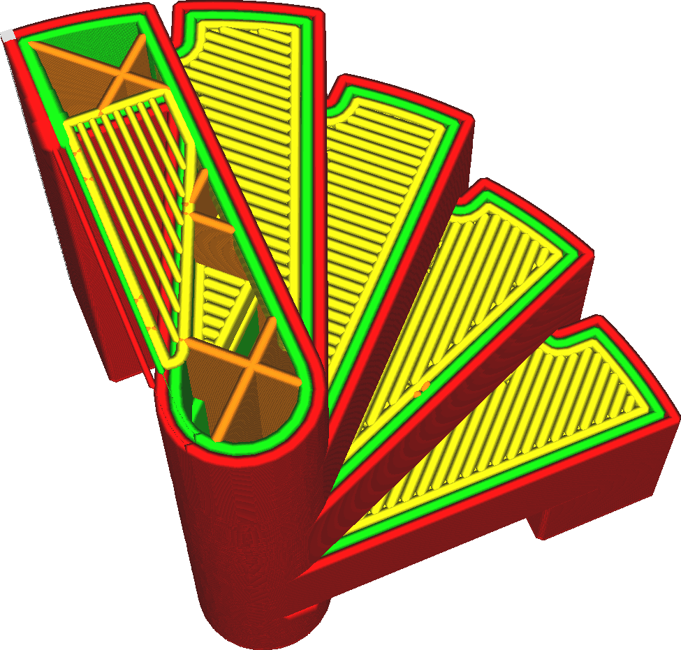
By enabling the bridging settings, you get greater control over how bridges are handled in your print. By tuning the bridging parameters very well, you can improve the quality of your overhangs significantly and improve accuracy in the vertical direction.
¶ Retract at Layer Change
If enabled, the filament will be retracted when moving to the height of the next layer.
This can be used to reduce the Z seam on the surface. However, it will only be effective if the retraction distance is very low. If the retraction distance is high, the duration of the retraction will allow the material to ooze so much that it counteracts the retraction.
¶ Maximum Retraction Count
Still working in progress...
Please refer to the explanation in Luban.