¶ 💡 Compatibility
This guide applies to the following machine. Please note when referencing:
- Machine model: U1
¶ ⏰ When to Use This Guide
The core principle of multi-toolhead printing lies in establishing precise coordinate offsets between each print head. Therefore, when performing multi-color printing with the U1, the following issues are typically associated with inaccurate toolhead offset calibration data or abnormal mechanical conditions. Refer to this guide for troubleshooting if you encounter any of these symptoms:
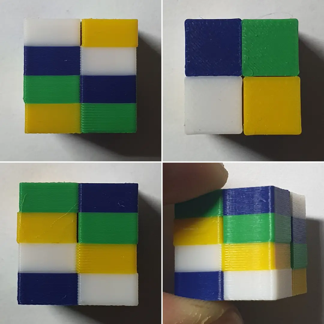
- Noticeable misalignment between different colors;
- Overlaps or gaps at color transition areas;
- Printed parts that fail to fit together or show visible spacing.
¶ 📋 Quick Info Card
- Difficulty: ⭐⭐☆☆☆ (Easy)
- Estimated Time: 20 minutes
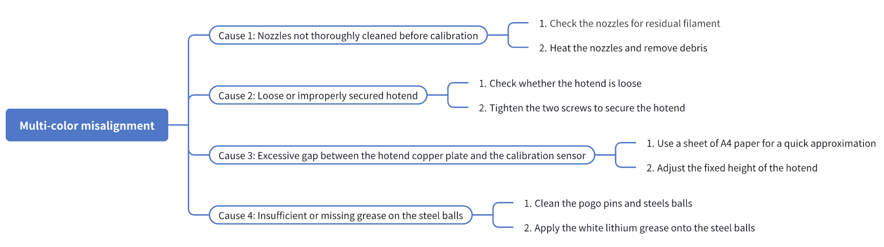
¶ 🔁 Troubleshooting Flowchart
¶ 🔍 Quick Diagnosis
Which situation are you experiencing?
- Nozzles not thoroughly cleaned before calibration → Go to Step 1
- Loose or improperly secured hotend → Go to Step 2
- Excessive gap between the hotend copper plate and the calibration sensor → Go to Step 3
- Insufficient or missing grease on the steel balls → Go to Step 4
¶ ⚠️ Important Notes
When removing the toolhead or related components, make sure the machine is powered off and fully cooled down before proceeding.
¶ 🪄Preparation
¶ 1. Update Firmware
We recommend updating the firmware to the latest version (click to view the U1 Firmware Release Notes). New versions address known issues and can help improve print quality.
¶ 2. Unload Filament
Before starting the following troubleshooting steps, please unload the filament for the corresponding toolhead. Depending on the material type, you can refer to Rigid Filament Unloading or Flexible Filament Unloading.
¶ 3. Level the Heated Bed
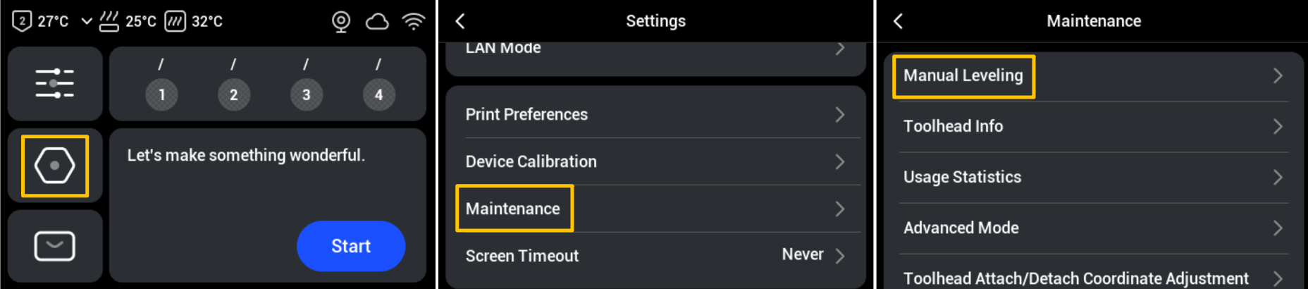
- On the touchscreen main interface, go to Settings > Maintenance > Manual Leveling, and follow the on-screen instructions to complete the leveling process.
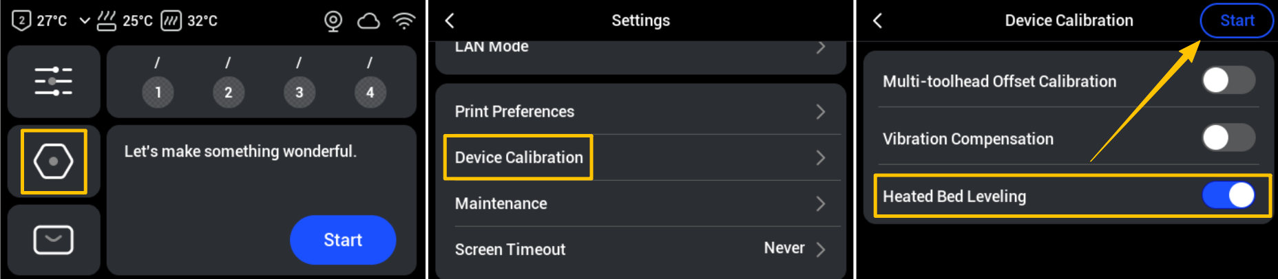
- After completing the manual leveling, please run the automatic bed leveling: return to the Settings page > Click Device Calibration > Enable Heated Bed Leveling > Start.
¶ 🛠️ Troubleshooting Steps
¶ Step 1: Check the nozzles for residual filament
If filament is stuck to the bottom of a nozzle, it can alter the nozzle’s effective trigger height. Therefore, before calibration, ensure that each nozzle extrudes smoothly and is free of residue.
- From the touchscreen control page, detach the current toolhead and make sure all toolheads are properly docked in their parking positions.
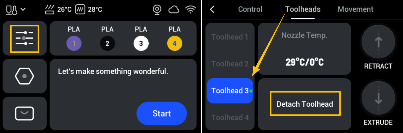
- Remove the four toolheads one by one and inspect the bottom of each nozzle for any remaining filament.
U1 toolheads are magnetically secured. When removing a toolhead, slide it in the opposite direction of installation: slide Toolhead 1 to the right, and slide Toolheads 2-4 to the left.
- If residue is found on the nozzle, reinstall the toolhead and heat the nozzle to the filament’s recommended temperature. Then use tweezers, a wire brush, or similar tools to carefully remove any residual filament.
¶ Step 2: Check whether the hotend is loose
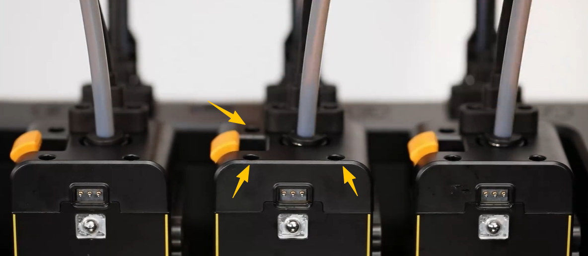
- After powering off the machine, use a H2.0 hex key to loosen the three screws shown in the illustration and remove the toolhead top cover. Then remove the toolhead from its docking position.
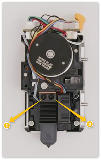
- Gently wiggle the toolhead to check whether the hotend is firmly secured. Any noticeable movement typically indicates that the screws are not fully tightened or have become loose. Remove the rear cover of the toolhead, then use the H2.0 hex key to tighten the two screws that secure the hotend.
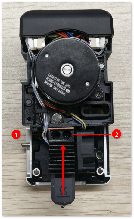
¶ Step 3: Check the gap between the hotend copper plate and calibration sensor
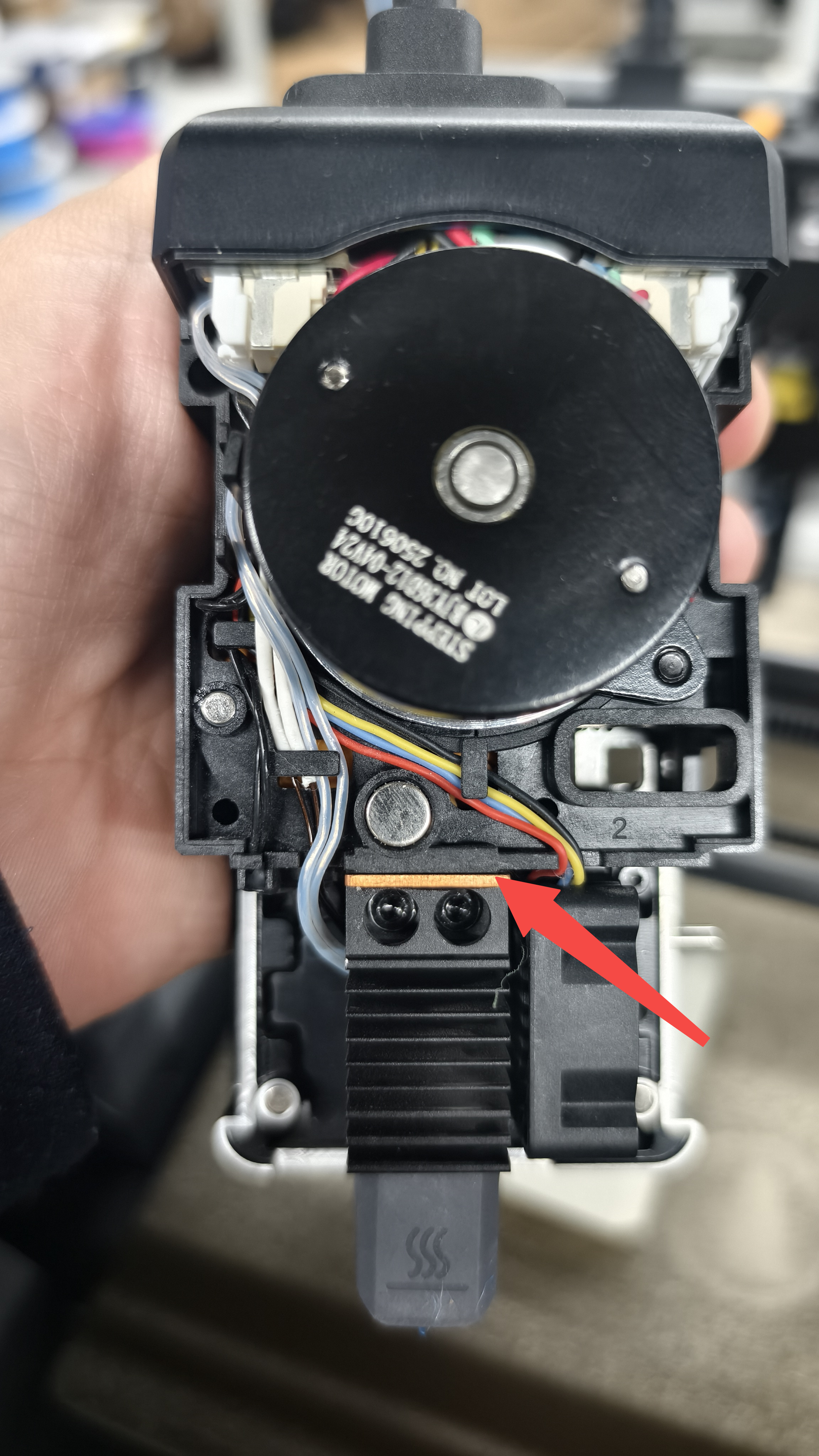
If the gap between the hotend copper plate and the calibration sensor is too large, it may cause delayed triggering, an elevated calibration height, and inconsistent Z references across multiple toolheads.
- Under normal conditions, the distance between the hotend copper plate and the calibration sensor should be within 0.1–0.4 mm. You can use a sheet of standard A4 paper for a quick approximation.
- If the gap is too large, use a H2.0 hex key to loosen the two screws securing the hotend, push the hotend upwards, and then re-tighten the screws.
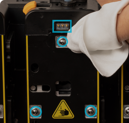
¶ Step 4: Check the lubrication of the steel balls
Insufficient lubrication of the steel balls over time can increase running resistance, causing positioning errors and affecting print quality.
- Use a clean wiping cloth lightly dampened with alcohol to gently clean the surfaces of the pogo pins and steel balls, removing dust, oil, and old grease.
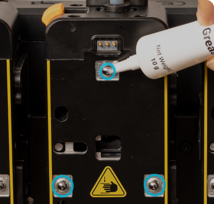
- Then, take the white lithium grease from the included tool kit and apply an even layer of appropriate amount onto the steel balls.
¶ ✅ Verification
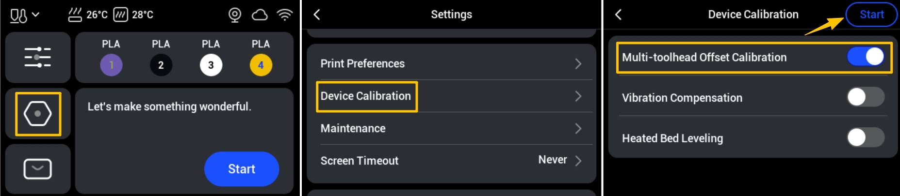
- After completing the above steps, run the multi-toolhead offset calibration. On the touchscreen main interface, go to Settings > Device Calibration > Multi-toolhead Offset Calibration and follow the on-screen instructions to complete the process.
- Print a four-color test model and observe:
- Are the boundaries clear?
- Are there any gaps?
- Is there any color overlap?
If the model fits naturally, the offset has been restored to normal.
To ensure consistent print quality, we recommend:
(1) Regular Cleaning: Check and clean the nozzles before running device calibration.
(2) Regular Calibration: Perform calibration whenever you move the printer, replace the toolhead or hotend, or carry out major maintenance.
(3) Regular Lubrication: Clean and lubricate moving parts quarterly, or adjust the schedule based on actual grease consumption.
¶ 📚 Related Resources
- U1 Firmware Release Notes
- Rigid Filament Unloading
- Flexible Filament Unloading
- U1 core components maintenance guide
- U1 Video Guide: Toolhead Disassembly
¶ 💬 Reach out to Snapmaker Support
After following the troubleshooting steps, if you find it difficult to resolve your issue, kindly submit a support ticket through https://snapmaker.formcrafts.com/u1-troubleshooting-request and share your troubleshooting results with pictures or videos. Our dedicated support team will be more than willing to assist you in resolving the issue.