¶ Before You Start
Download the latest version of Fusion 360 from its official website and install it on your computer.
-Autodesk Fusion 360 is now renamed as "Autodesk Fusion", which drops the "360" from the name.
-There is a 30-day free trial available for new users of Fusion 360, and you can access Fusion 360 Education Version if you are a student or teacher.
¶ Tools & Accessories Required
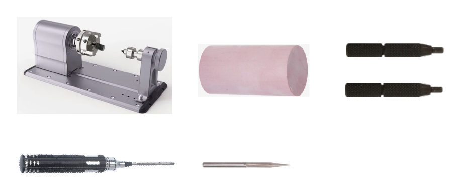
To illustrate how to use Artisan with Fusion 360 for 4-axis CNC machining, we will walk you through a simple project (carving the text on a cylinder material with CNC). During machining, you will need the tools and materials listed below.
- Rotoray Module ×1
- Material for 4-axis CNC ×1 (Length: 70mm, Diameter: 35mm)
- Chunk wrench × 2
- H2.5 screwdriver × 1
- Straight Groove V-bit ×1
¶ Procedures
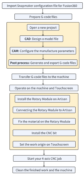
The following flowchart outlines the procedures to use Artisan with Fusion 360 for 4-axis CNC machining.
¶ Step 1: Import Snapmaker configuration files into Fusion 360
- Download Snapmaker configuration files for Fusion 360 from here.
- Unzip and open the downloaded file, copy the Fusion folder to Users > Username > AppData > Roaming > Autodesk > CAM 360 > libraries > Local.

¶ Step 2: Prepare G-code files
¶ Open a new project
On the top left navigation bar, click New Design.

You can also import your own model file into Fusion 360 by clicking Open > Open from my computer.
¶ Design a model file (CAD)
In this part, we will create a cylinder first, then try to put some text on it for later carving.
¶ Create a cylinder
- Switch to DESIGN workspace. Switch the viewcube to Front.

- Click Create > Create Sketch.

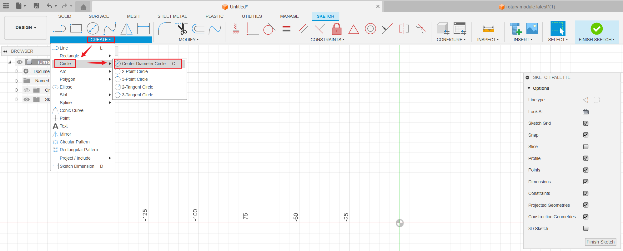
- Click Create > Circle > Center Diameter Circle.
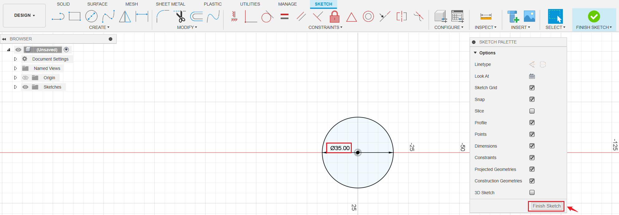
- Drag to draw a circle and set its diameter to 35mm. Then click Finish Sketch.
- Click Extrude.

- Select the circle for Profiles, select Object for Start, set Distance to 70mm, click OK when finished.
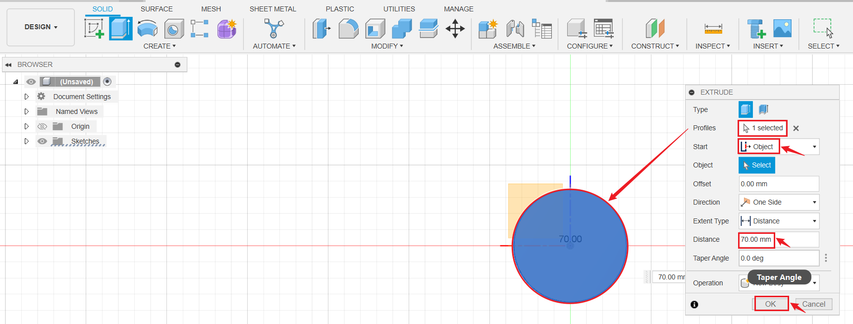
Now we've got the cylinder ready. Let's put some text on it!
¶ Put some text on the cylinder
- Switch the viewcube to TOP.

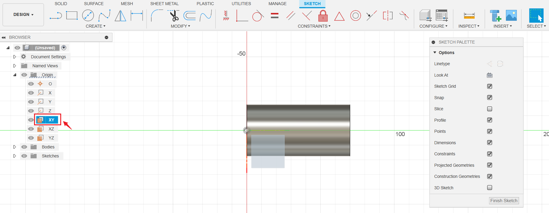
- Click Create > Create Sketch.

- Select XY panel.
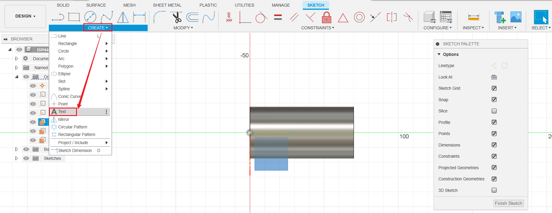
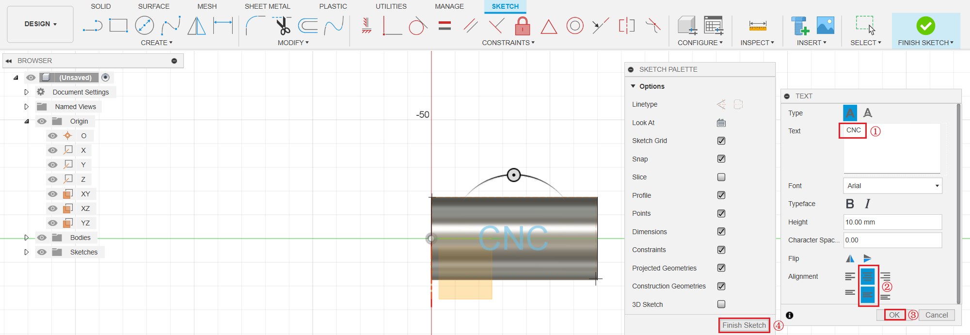
- Click Create > Text.
- Place the cursor on the following 2 points to set the text frame.
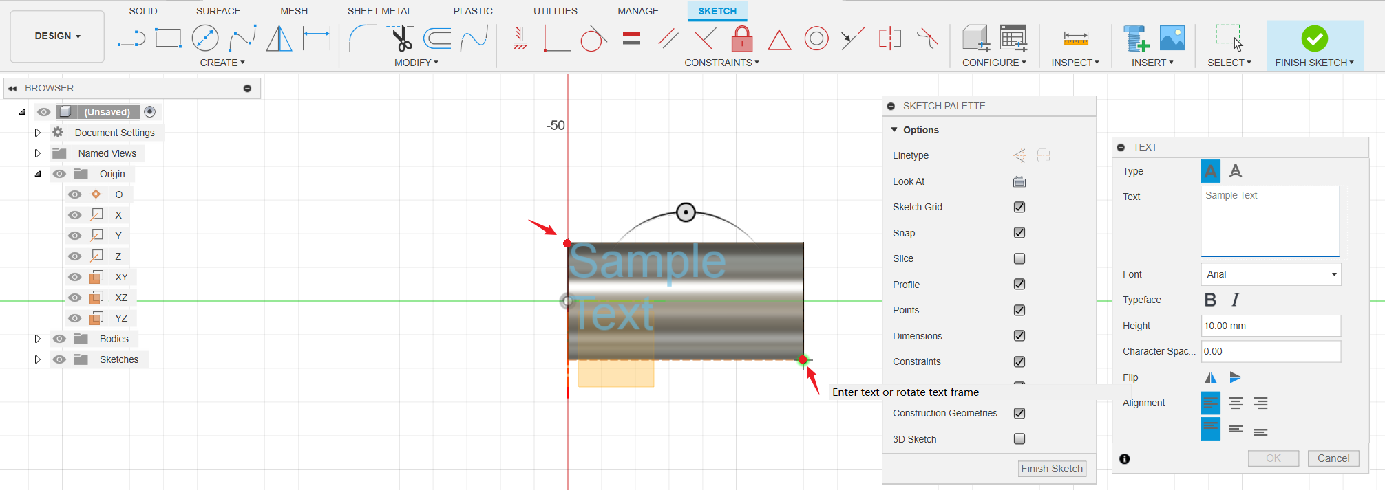
- Type the text you want to engrave, align the text to center, then click OK and Finish Sketch.
- Click Extrude.
- Select the text for Profiles. Select Start as Object, then select the cylinder surface as Object. Set Distance to -3mm, and select Operation as Cut. Click Ok when finished.
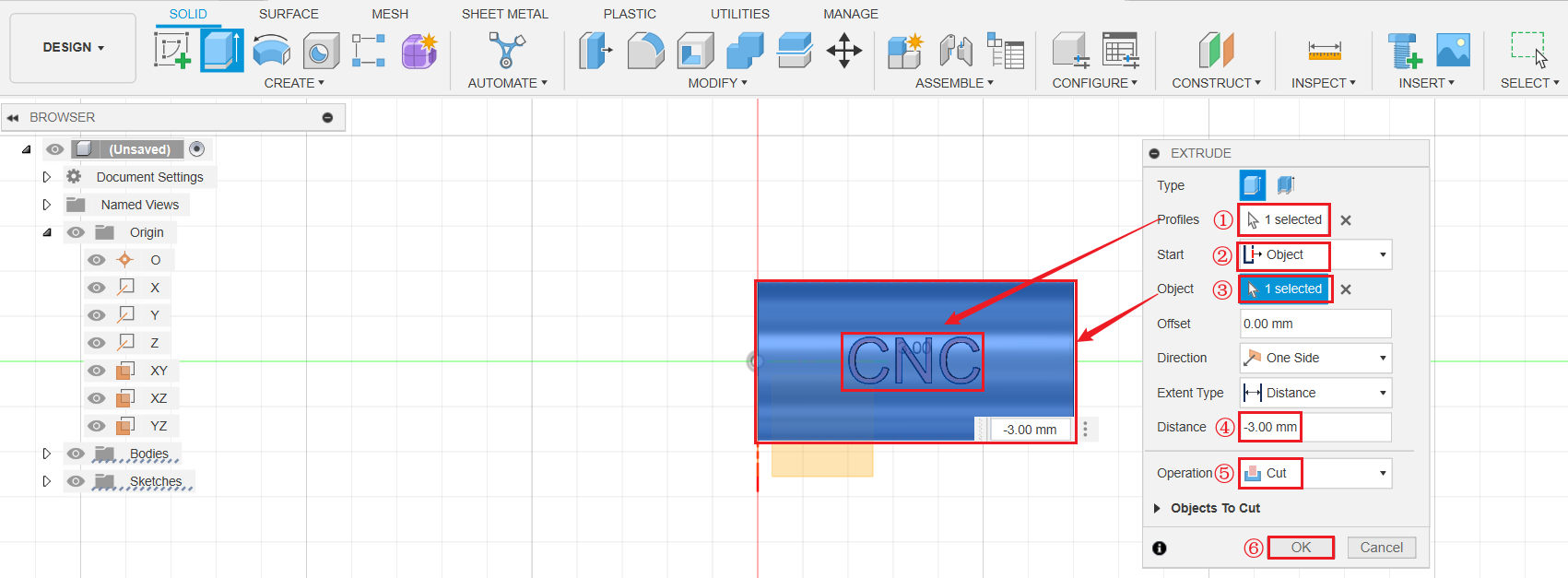
Now we've got the model file ready. Let's set the toolpath for it!
¶ Configure the manufacture parameters (CAM)
¶ Create Setup
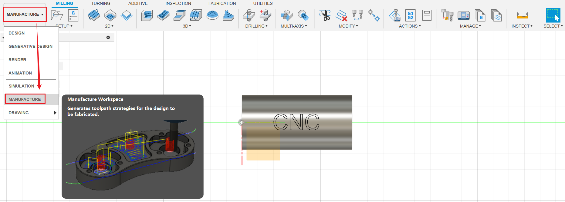
- Switch to MANUFACTURE workspace.
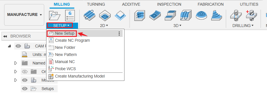
- Click SETUP > New Setup.
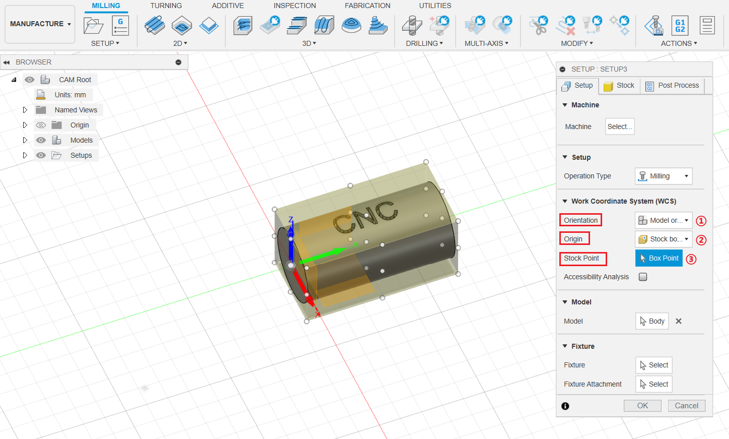
- Under Setup tag, set Orientation as Model orientation, select Origin as Stock box point. Then click Box Point, select the centerpoint of the left side circle as Stock Point, as shown below.
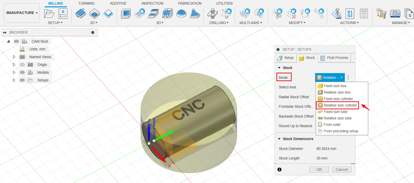
- Under Stock tag, set Mode as Relative size Cylinder.
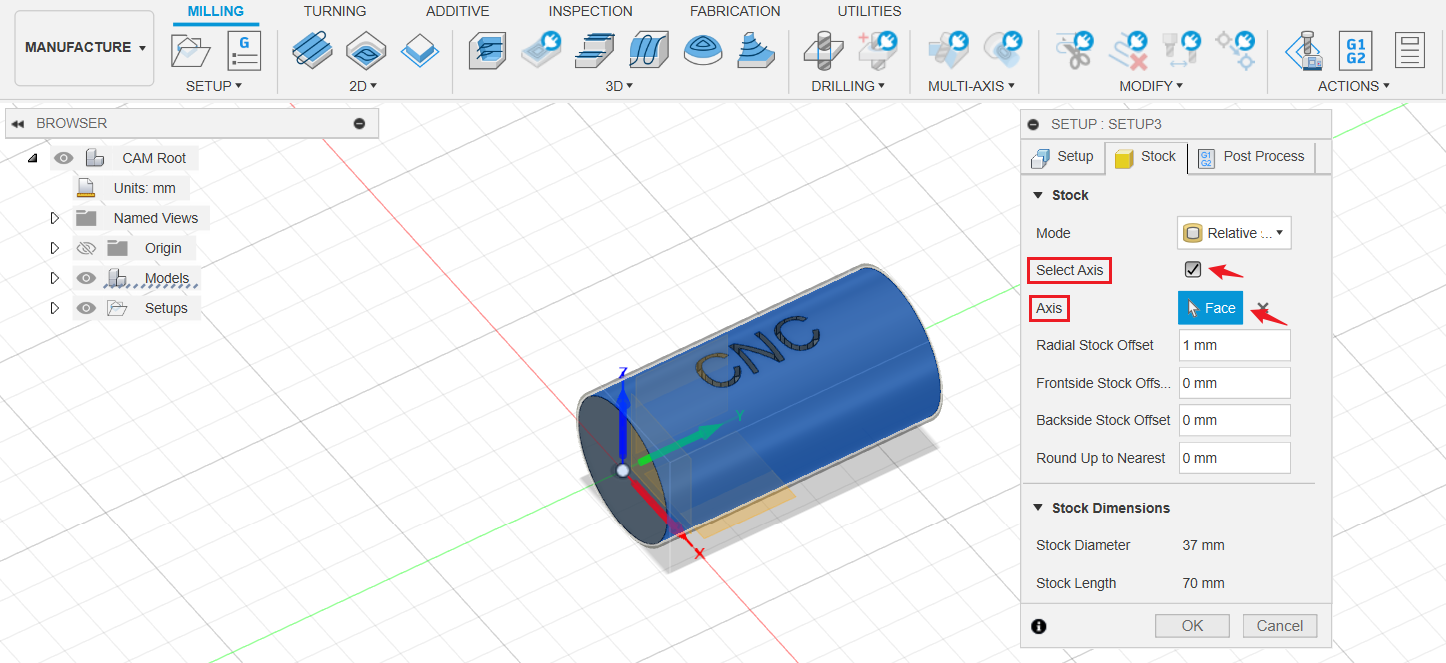
- Tick Select Axis, then select the cylinder surface.
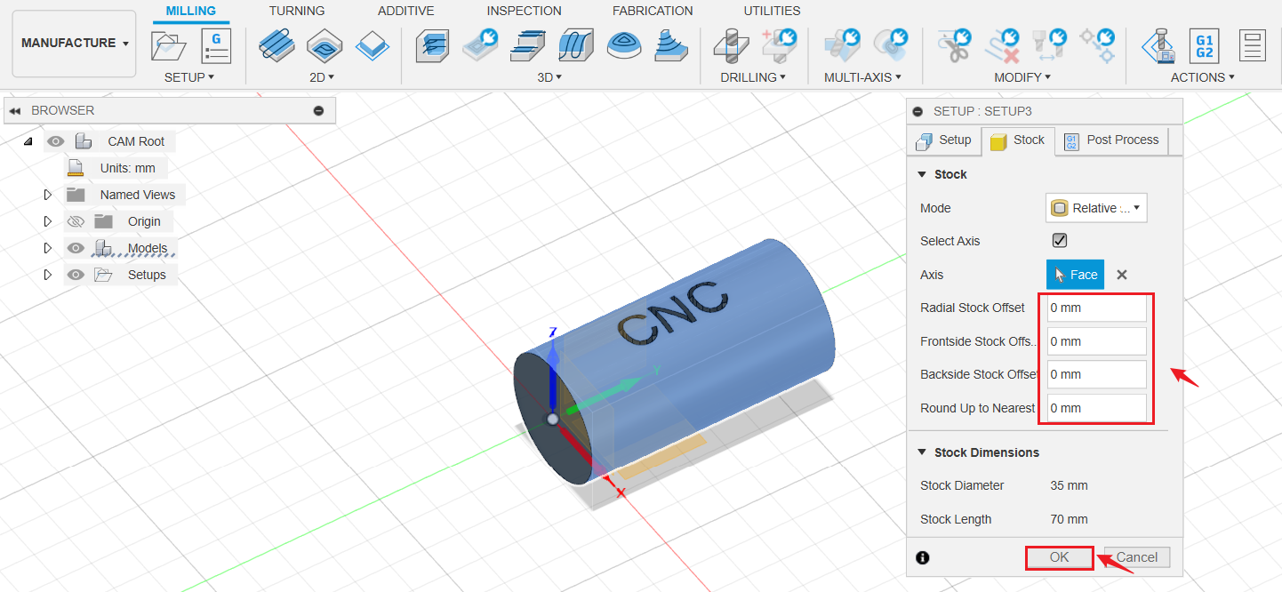
- Set Offset at each side to 0mm, then click OK.
¶ Create the toolpath
2D contour is known as a 2D machining approach. However, it also provides the "Wrap" function, which allows for machining with 4 axes.
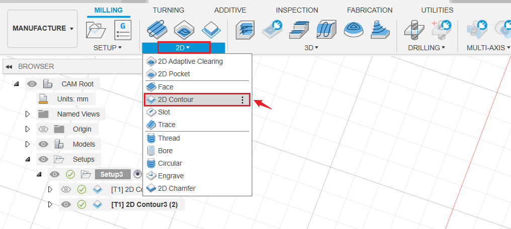
- Click 2D > 2D Contour.
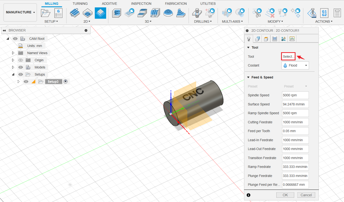
- Click Select to select the tool.
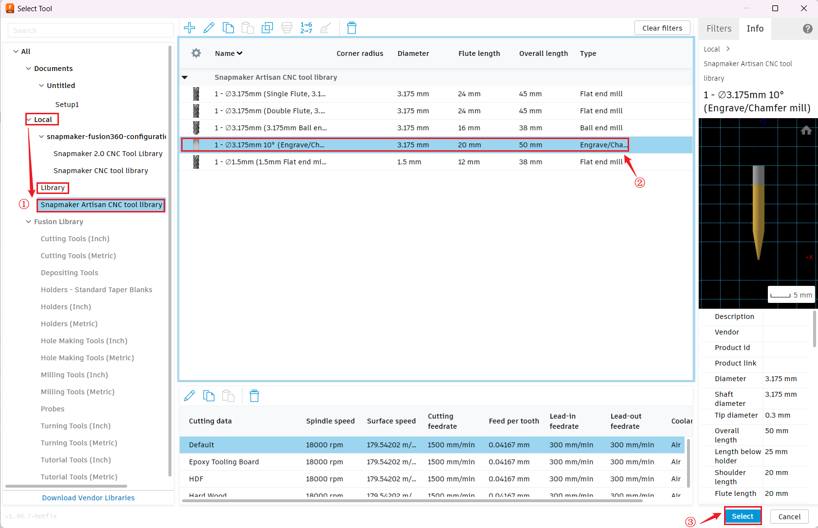
- Click Local > Library > Snapmaker Artisan CNC tool library, select Engrave/Chamfer mill, then click Select.
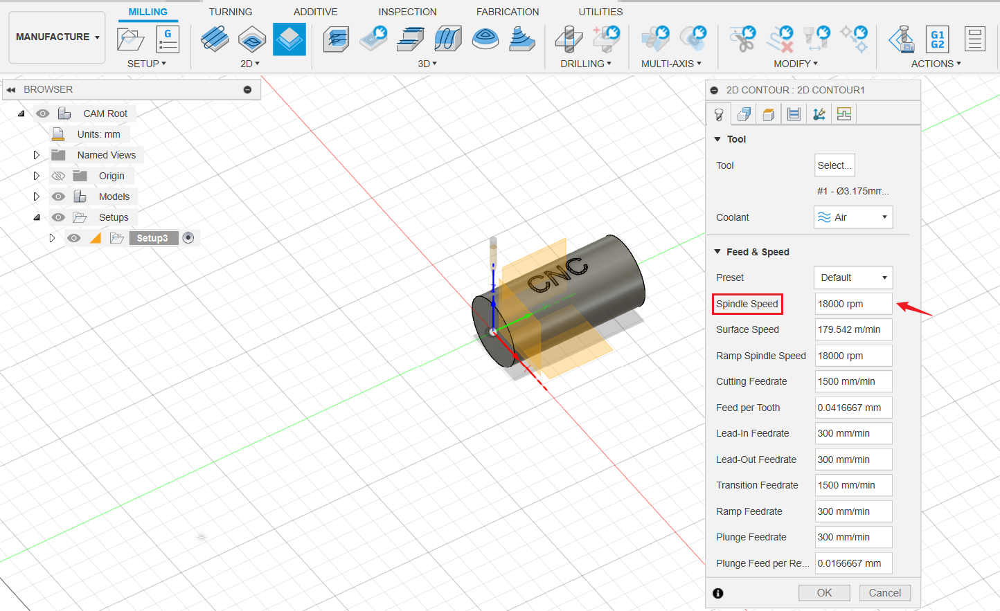
- Set Spindle Speed to 18000 rpm.
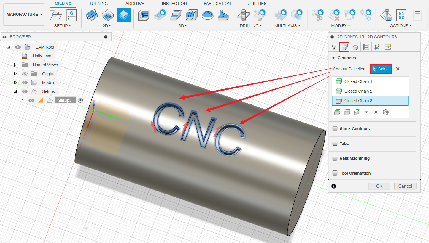
- Switch to Geometry tag, click Select and select the text surface outline as Contour Selection.
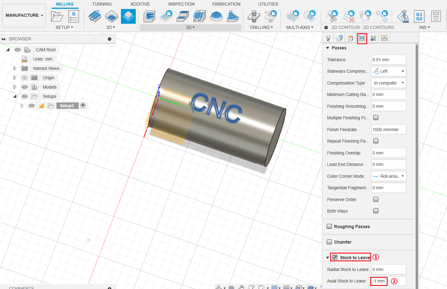
- Switch to Passes tag, tick Stock to Leave, then set Axial Stock to Leave as -1mm.
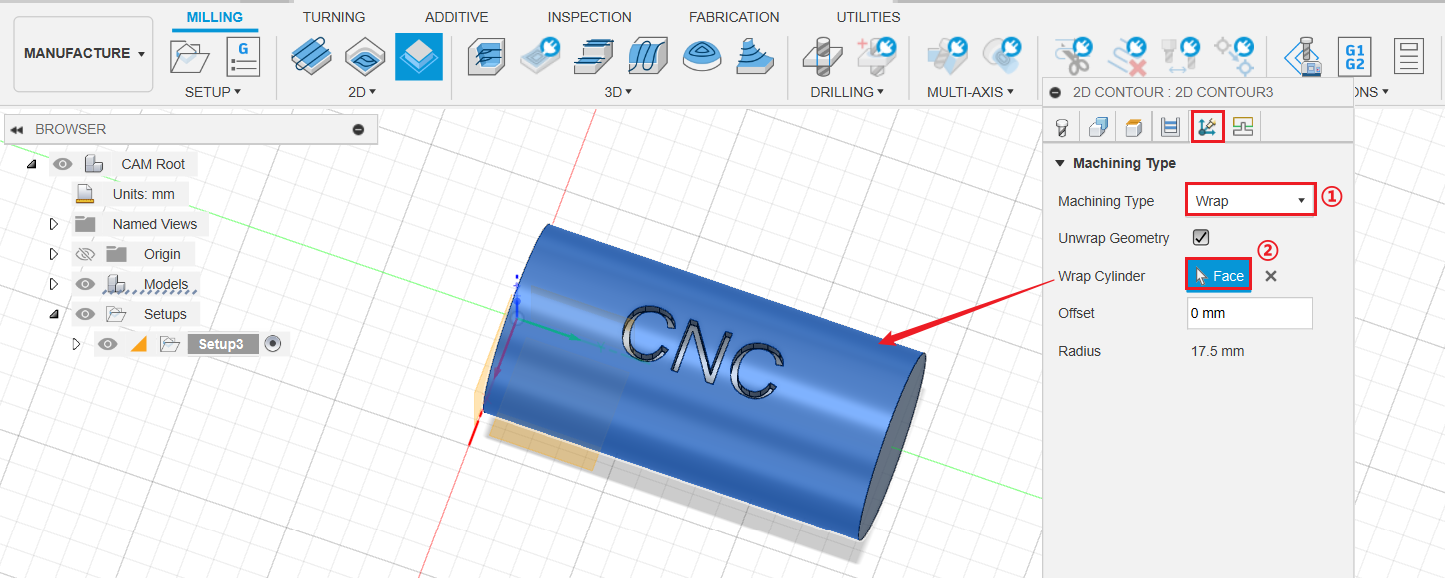
- Switch to Multi-Axis, set Machining Type as Wrap. For Wrap Cylinder, select the cylinder face.
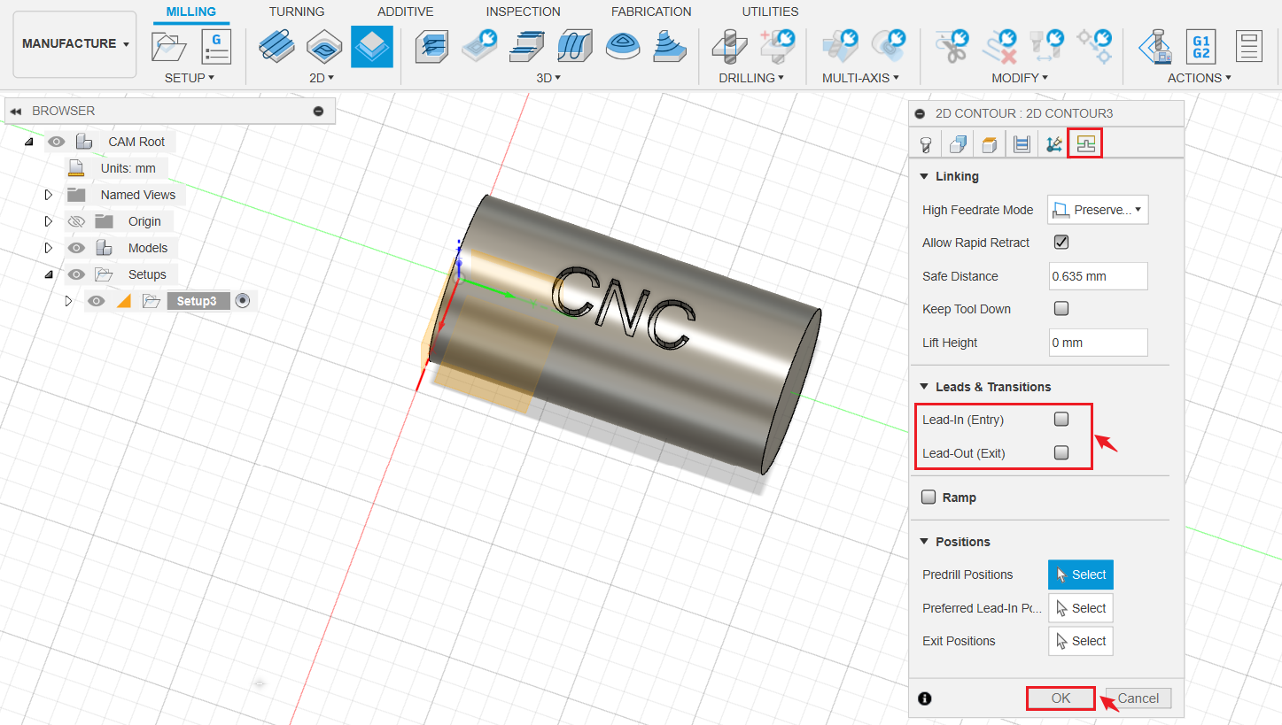
- Switch to Linking tab, untick Lead-in (Entry) and Lead-out (Exit). Click OK when finished.
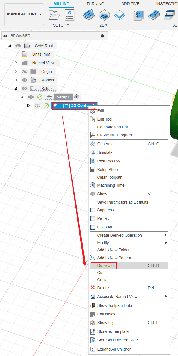
- Right-click [T1] 2D Contour, then click Duplicate to create a copy of the 2D contour toolpath.
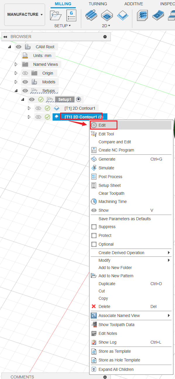
- Right-click the copied toolpath, then click Edit.
- Under Passes tag, adjust Axial Stock to Leave to -2mm. Then click OK.
[Image] - Right-click [T1] 2D Contour, then click Duplicate to create another copy.
- Right-click the copied toolpath, then click Edit.
- Adjust Axial Stock to Leave to -3mm. Then click OK.
Now G-code is almost ready. We are ready to do post processing and export the G-code.
¶ Post process: Generate and export G-code files
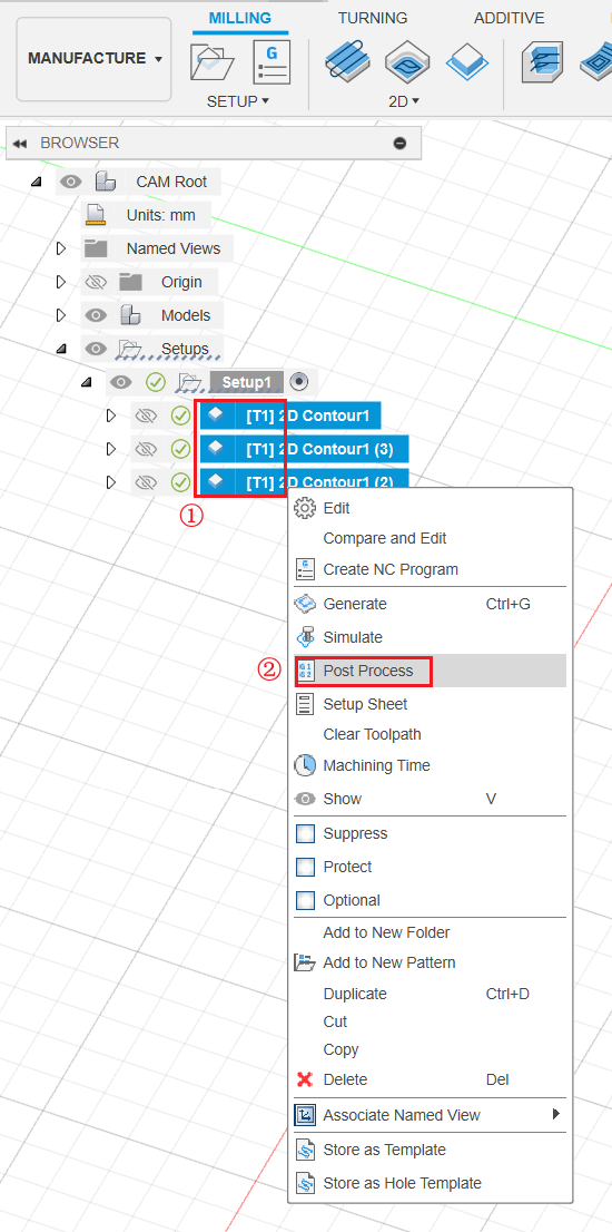
- Select 3 toolpaths, right-click and select Post Process.
- Select the FANUC - Inverse Time and A-axis as Post. Then input your file name, select output folder, and click Post.
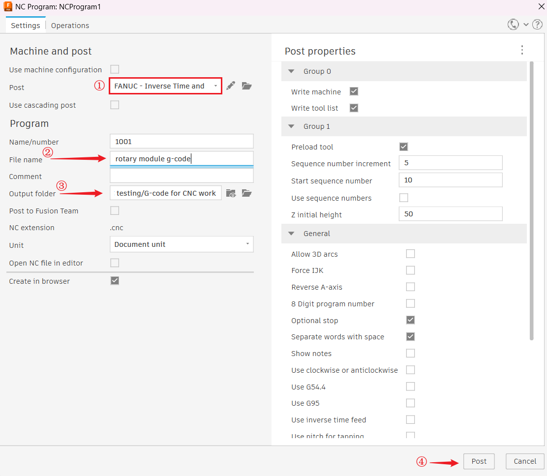
If it's your first time using Fusion 360, please refer to Snapmaker post process in Fusion 360 (4-axis) to import Snapmaker post processor for 4-axis CNC machining: FANUC - Inverse Time and A-axis.
Snapmaker has different post processors for 3-axis and 4-axis CNC machining. Make sure you have selected the correct post processor, otherwise you may fail to generate G-code.
¶ Step 3: Transfer G-code file to the machine
- Copy the exported .cnc G-code file to USB flash drive.
- Insert USB flash drive into the Integrated Controller.
- On Touchscreen, tap Start > Files > Local, you will find your .cnc G-code file.
¶ Step 4: Operate on the machine and Touchscreen
If you are using the rotary module, please refer to Assemble the Rotory Module to assemble it first.
Before the assembly, be sure to turn off the machine first.
¶ Install the Rotary Module on Artisan
¶ Connecting the Rotary Module to Artisan
¶ Fix the material on the Rotary Module
¶ Install the CNC bit
¶ Set the work origin on Touchscreen
Make sure you've not installed the tailstock yet.
Make sure you've worn the safety glasses.
If the CNC bit bumps into the machine, turn off the machine or press the emergency stop button immediately.
- On the Touchscreen, tap Tools > Origin Assistant > Start.
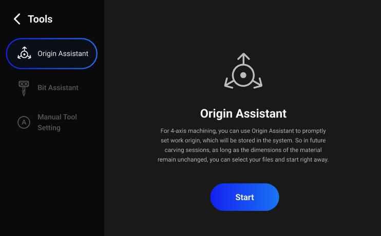
- Follow the on-screen instructions to complete the setup.
The length of the material is 70 mm, and the diameter is 35 mm.
¶ Step 5: Start your 4-axis CNC job
Tap Start Job on the Touchscreen to start your CNC job.
¶ Step 6: Clean the finished work and the machine
Adjust the handwheel and remove the finished work with the two chuck wrenches.
Till now, you should get cylinder with some text carved on it.