¶ Move
When you load a model into Luban, it is automatically placed at the center of the build plate. However, you can use the move tool ![]() to adjust the model position and make basic arrangements.
to adjust the model position and make basic arrangements.
¶ Model Position
You can use one of the following options to adjust the model position:
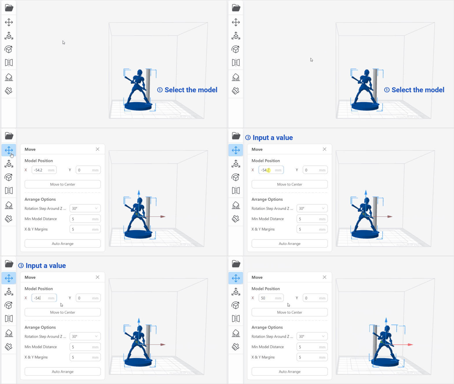
¶ Option 1: Input a value
- Procedures:
- Select the model;
- Click the Move tool;
- Input a value;
- Press Enter.
¶ Option 2: Drag the axis arrow
- Procedures:
- Select the model;
- Click the Move tool;
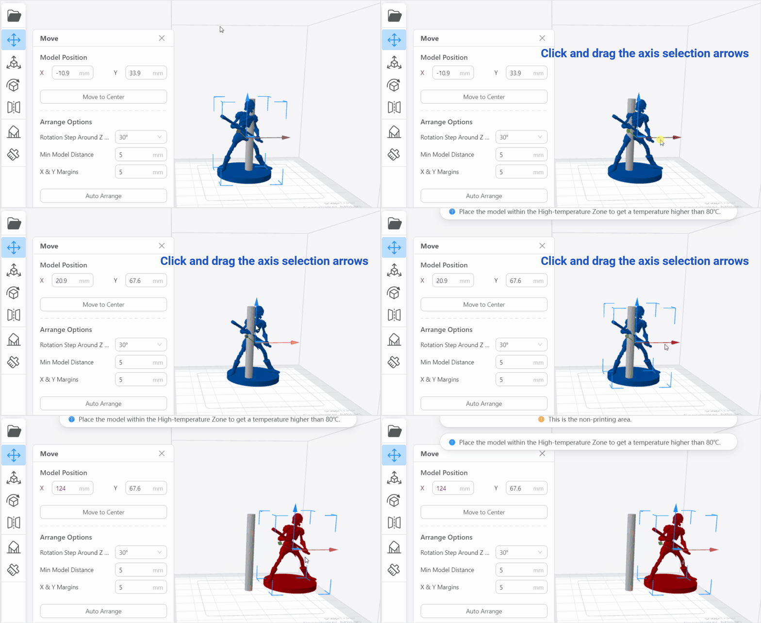
- Click and drag the axis selection arrows marked in red, green, or blue, the model will be moved.
When you hover the selection arrow over one axis, the color of the hovered axis will appear darker.
-The objects, even moved along the Z axis, will jump back to touch the bottom of the printing area. This prevents the model from floating in mid-air.
-If the object extends beyond the printing area, it becomes red to alert you.
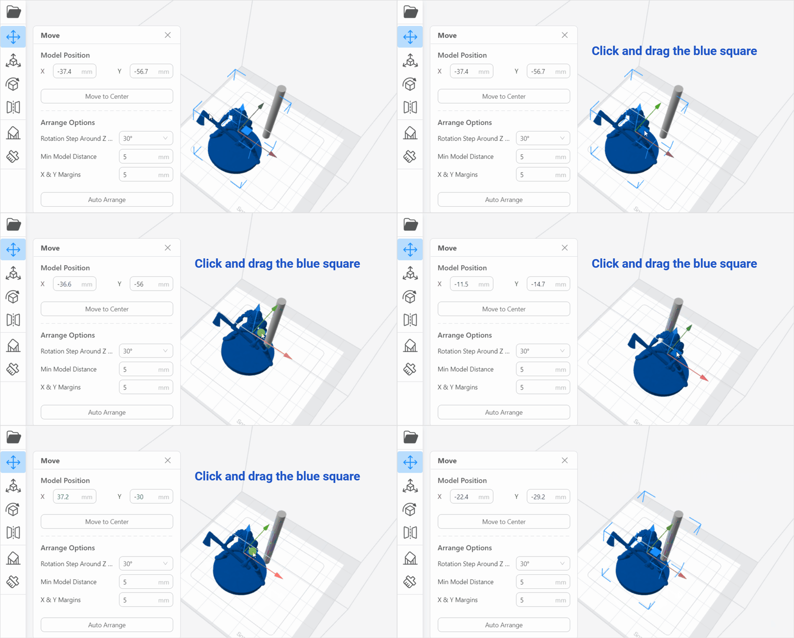
¶ Option 3: Drag the blue square
- Procedures:
- Select the model;
- Click the Move tool;
- Click and drag the blue square, the model will be moved.
When you hover the selection arrow over the blue square, the color of the hovered square will appear darker.
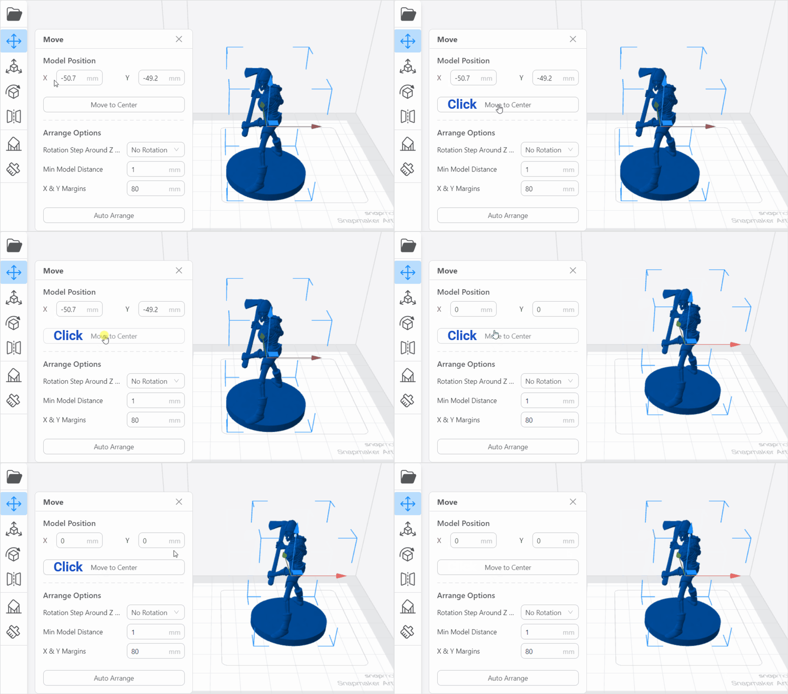
Besides the above three options, you can also click Move to Center to palce the model in the center of the build plate.
¶ Arrange Options
In addtion, the move tool also supports some basic arrange options, including Rotation Step Around Z Axis, Mini Model Distance and X & Y Margins.
¶ Rotation Step Around Z Axis
It refers to the unit angle at which the models rotate around the Z axis. You are allowed to choose from several rotation options: No Rotation, 20°,30°,36°,45°,60°,90° or 180°.
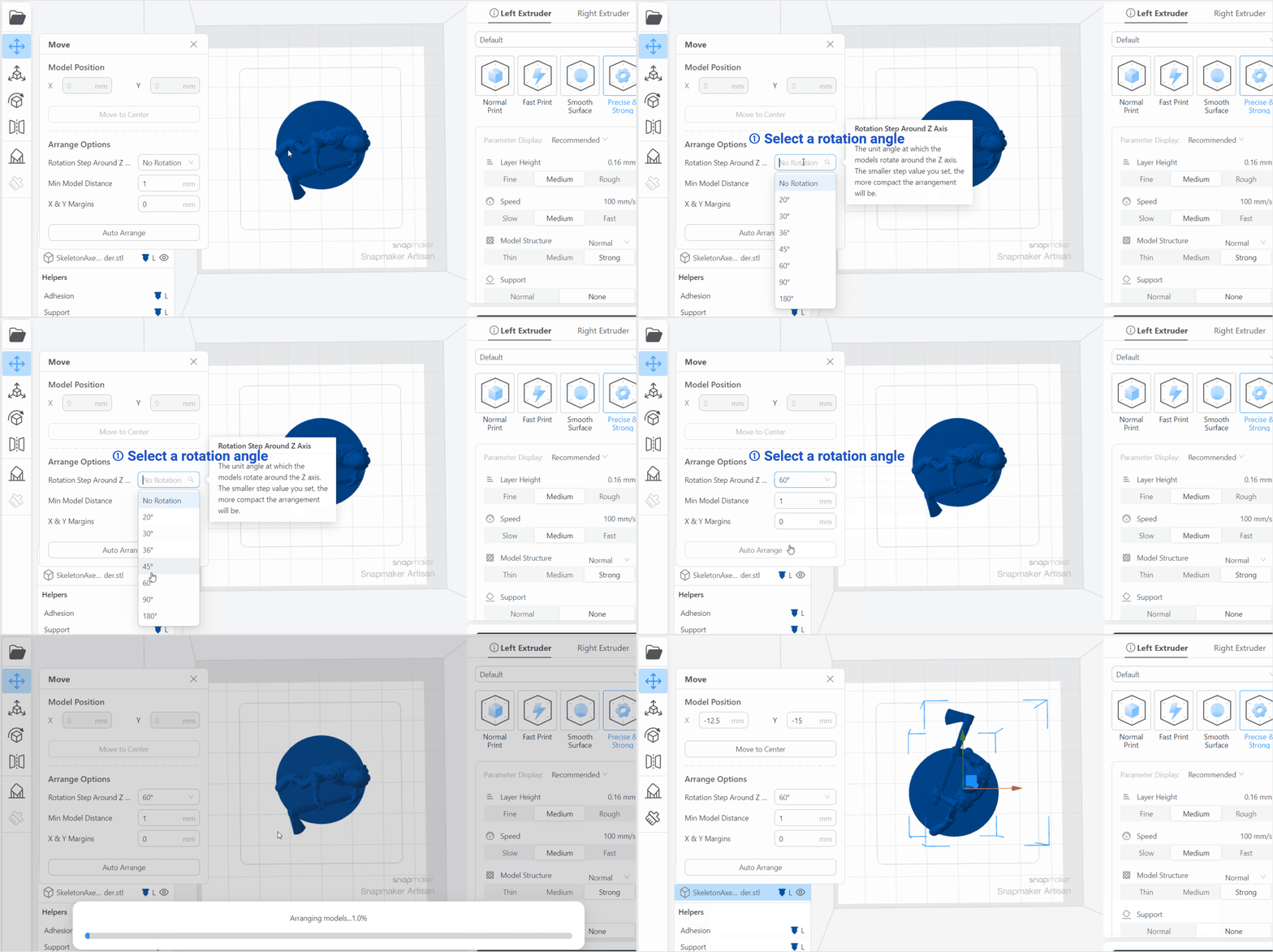
The smaller step value you set, the more compact the arrangement will be.
You can also right-click the mouse, then click Auto Arrange to apply the changes.
¶ Mini Model Distance
You can set the minimum distance between models.
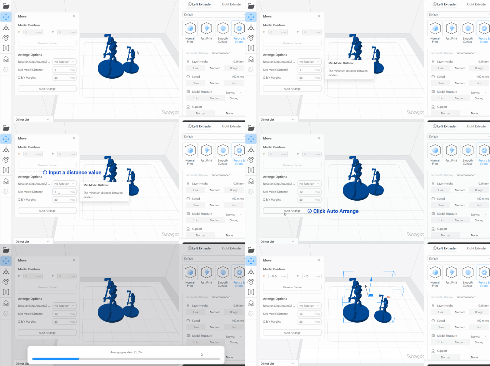
The minimum distance between two models should be at least 1mm.
¶ X & Y Margins
It refers to the blank spaces left between the print area and the edges in the X and Y coordinates.
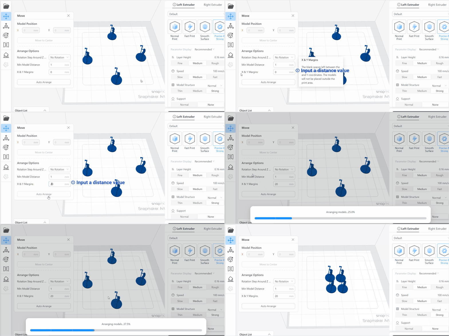
The models will not be placed outside the print area.
¶ Scale
With the scale tool ![]() , you can scale your model in any way you like.
, you can scale your model in any way you like.
¶ Uniform Scaling
-
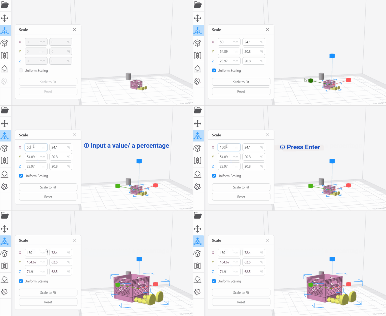
Enter a value/a percentage into the input box, then press Enter.
-
Click Scale to Fit to resize the object to fit the maximum printable area.
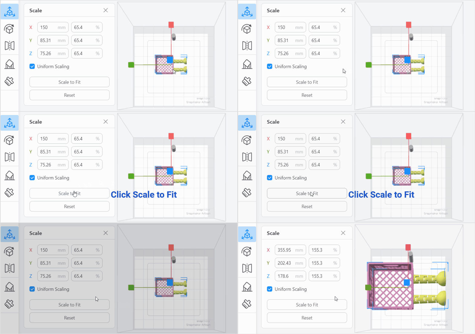
Although the model can be resized to fit the whole printable area, to improve print quality, it is recommended to place the model wintin the High-temperature Zone to get a temperature higher than 80°.
- Click Reset to reset all scaling modifications to the selected models.
¶ Non-uniform Scaling
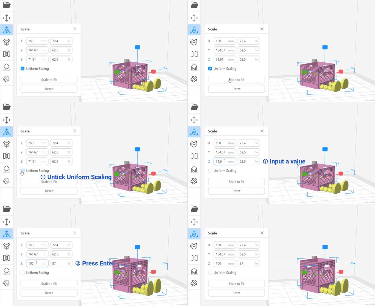
You can resize the object in a uniform or non-uniform way. When Uniform Scaling is enabled, the object enlarges or shrinks by one scale factor in all directions. When Uniform Scaling is disabled, the scaling can be applied to a single axis, without affecting other axes.
¶ Rotate
When you load a model into Luban, it is automatically placed on the build plate in the orientation that it was designed. With the rotate tool ![]() , you can rotate objects within the printing area.
, you can rotate objects within the printing area.
The rotate tool is useful to reduce the amount of support structure needed, change the layer bonding direction of the print, or increase the model's footprint for better build plate adhesion.
¶ Auto Rotate
It automatically adjusts the orientation of the object to best fit the actual orientation of the build plate.
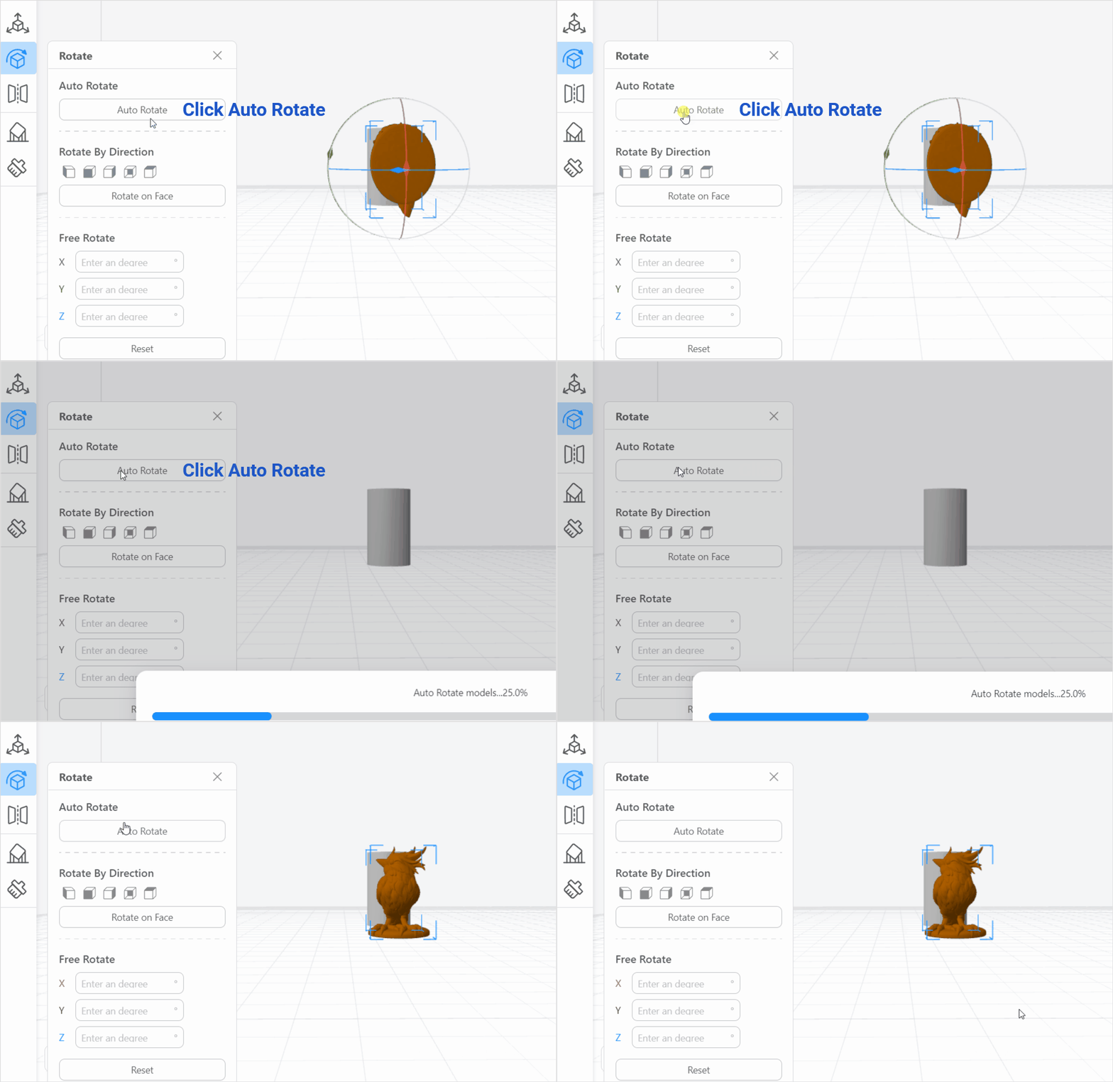
You can also select the model, right-click the mouse, then click Auto Rotate.
¶ Rotate on Face
You can choose a face as the rotate center. Then rotate the 3D model around the chosen face.
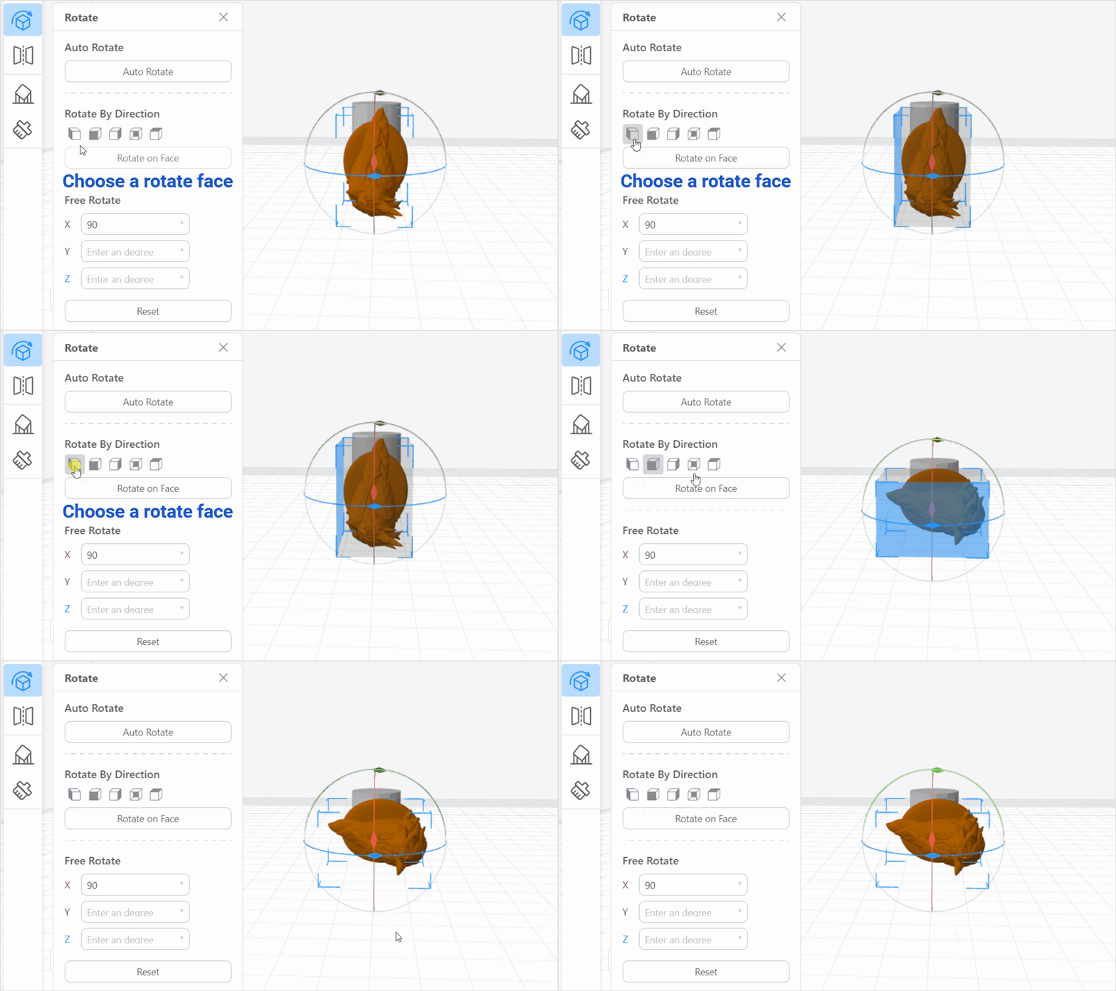
- Click Reset to restore the object to its original orientation.
¶ Free Rotate
- Click and drag the circle marked in red, green, or blue.
- Drag the red circle, and the object will rotate around the X axis.
- Drag the green circle, and the object will rotate around the Y axis.
- Drag the blue circle, and the object will rotate around the Z axis.

When you hover the selection arrow over one circle, the color of the hovered circle will appear darker.
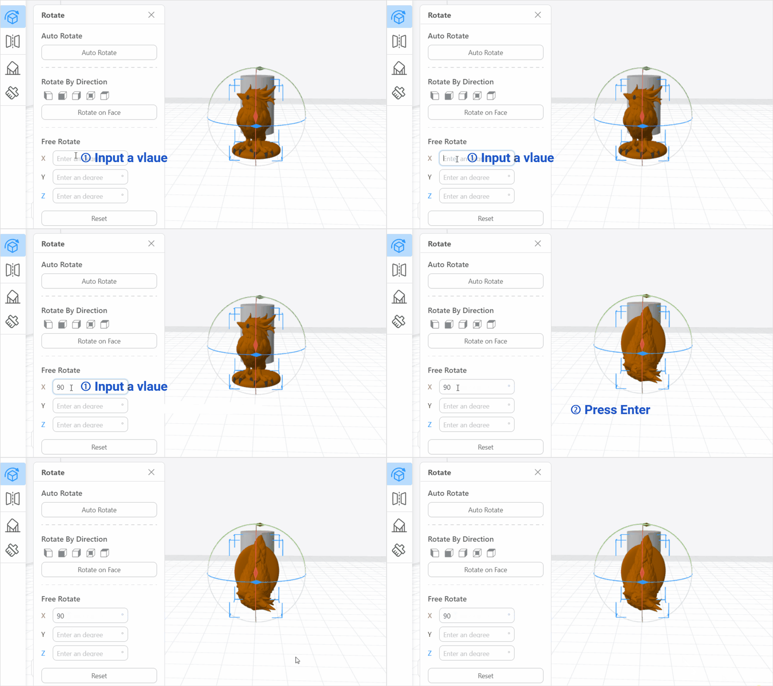
- Enter a value into the input box.
¶ Mirror
With the mirror tool ![]() , you can mirror your model along its X, Y, and Z axes.
, you can mirror your model along its X, Y, and Z axes.

If you are using J1/J1s IDEX print module, please note that this mirror tool differs from the Mirror Mode in print mode settings. This tool only produces the mirror version of your model, while Mirror Mode enables you to print the original model and its mirror version simultaneously and independently.
¶ Support
Most of models require support structures in order to be printed properly. In Luban, you can either use Auto Support feature to auto-generate the supports or use Manual Support feature to manually add or delete the support.
¶ Auto Support
-
Enter a proper value for overhang angle, then click Generate Auto Support.

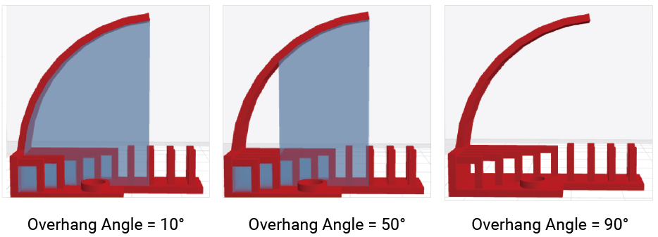
The overhang angle in 3D printing refers to the maximum angle at which a part of the model extends outward at an angle from the vertical axis of the object being printed. The 45° rule serves as a practical guideline when dealing with overhangs in 3D printing, and it is not recommended to set the angle bigger than 50°.
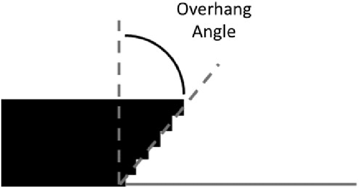
The overhang angle influences how much support material is added and where. A smaller angle leads to more support. For example, at a value of 10° most of overhangs are supported, while at 90° no support material is added.
¶ Manual Support
- Click Edit > Add or Delete to manually add or delete supports. Click wherever you want the supports added or deleted, then click Done.
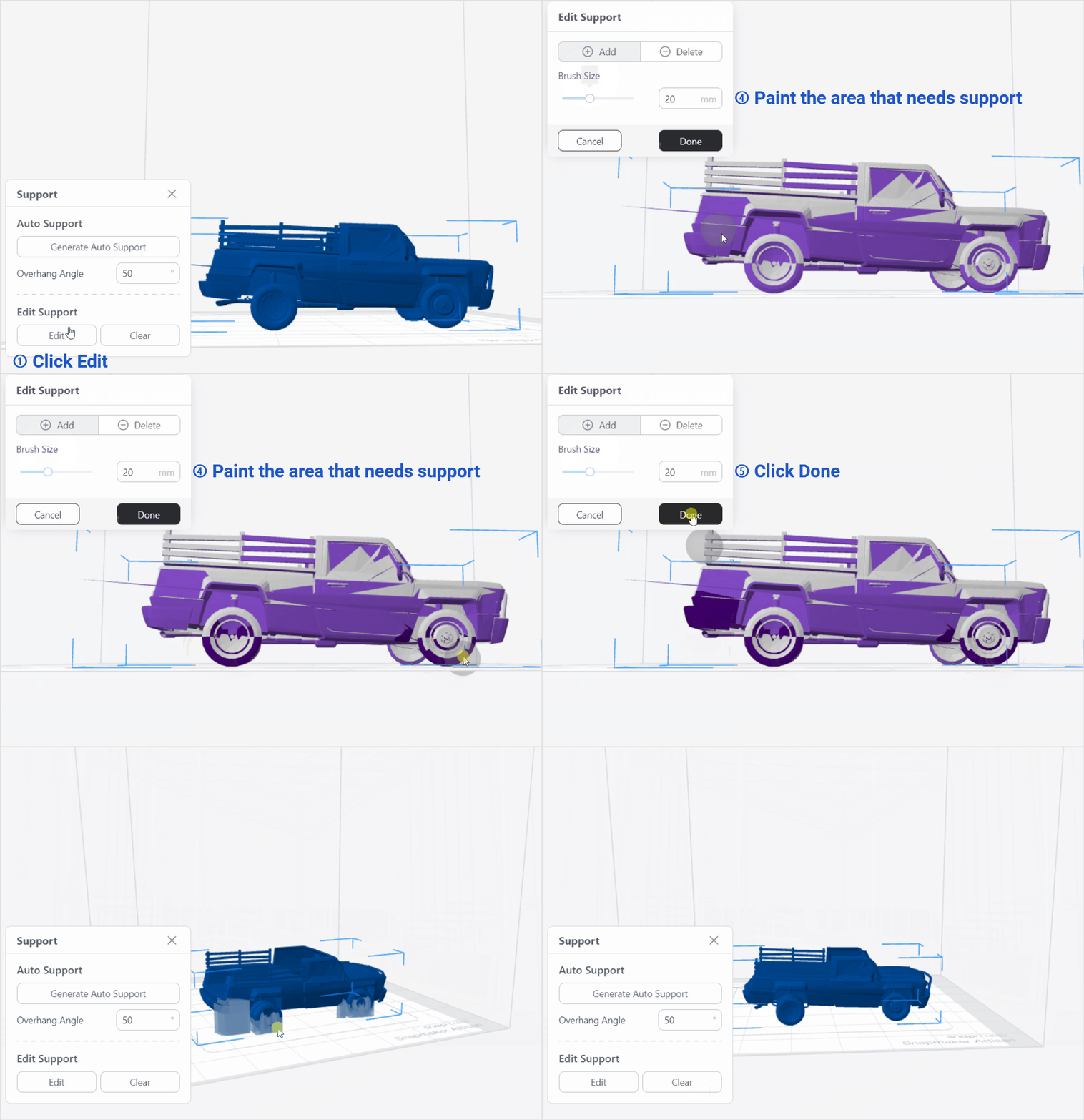
The purple surfaces represent the overhang area that Luban recommends to add supports.
Click Clear, all added supports will be cleared.
¶ Mesh Painting
To help users make the most of the dual extrusion model and IDEX printing, Luban has developed the mesh painting features, which allows designers to apply any two colors or any two materials on a single model, and accurately specify the areas where colors/materials are applied.
Specifically, it includes two tools: Smart Fill and Brush.
For dual-color or dual-material slicing guide, please refer to - Dual-color or Dual-material Slicing Guide.
¶ Smart Fill
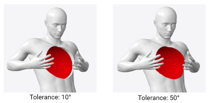
The models are composed of various triangles, based on the angle of the triangles around the clicked area, Smart Fill tool can automatically select and paint the triangles within the angular tolerance that you set. As you hover the mouse above the model, you will get a real-time preview of the automatically detected region to paint.

With smaller angle tolerance, sharp borders can be detected, thus smaller areas will be selected. With bigger angle tolerance, it will be more "tolerant" with the the borders, thus bigger areas will be selected and painted.
In terms of shortcut operations, it supports numbers 1 and 2 to switch color selection quickly.
¶ Brush
- Brush tool allows you to manually select the areas that you would like to paint.
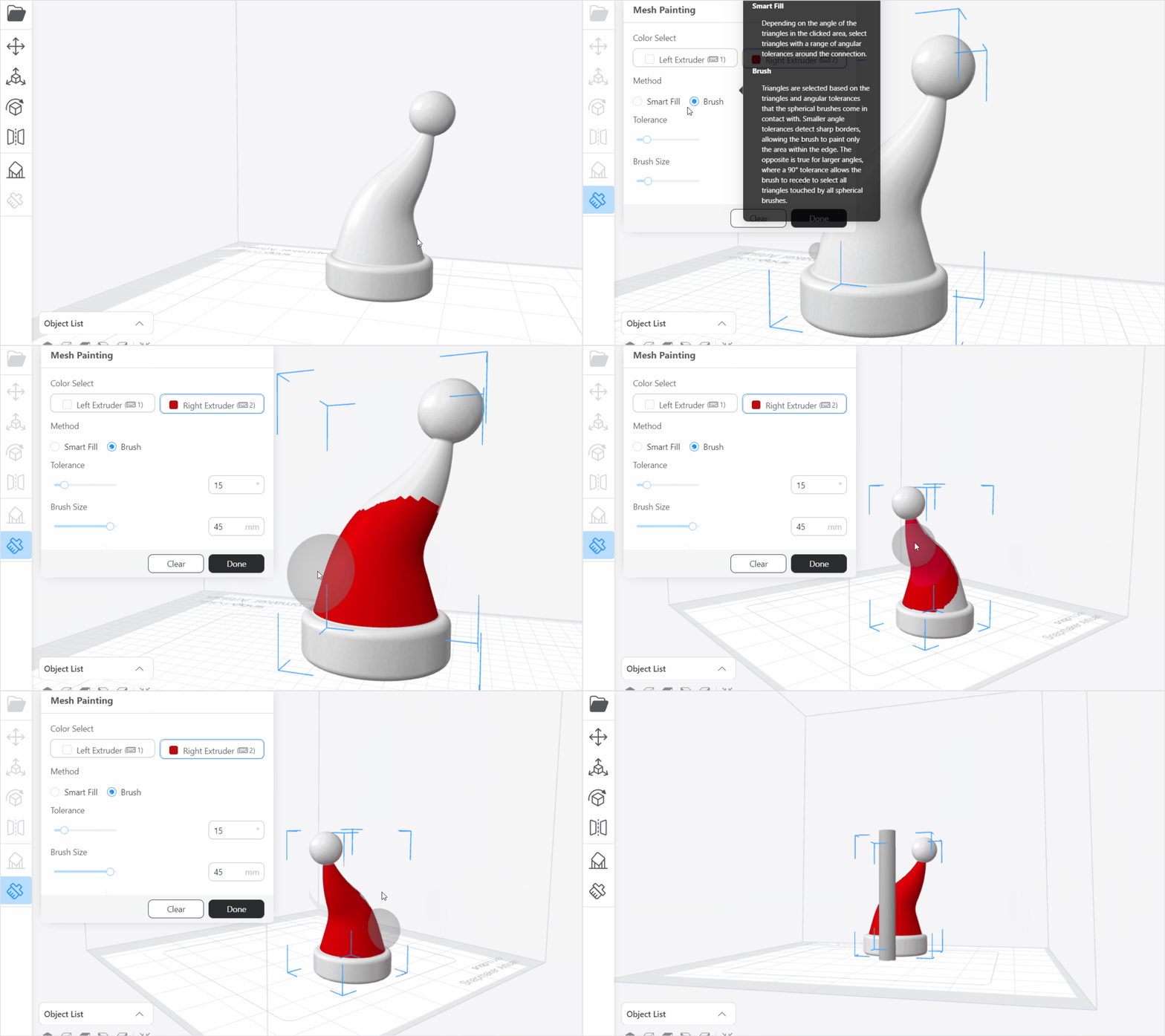
Triangles are selected based on the triangles and angular tolerances that the spherical brushes come in contact with.
¶ How to clear mesh painting
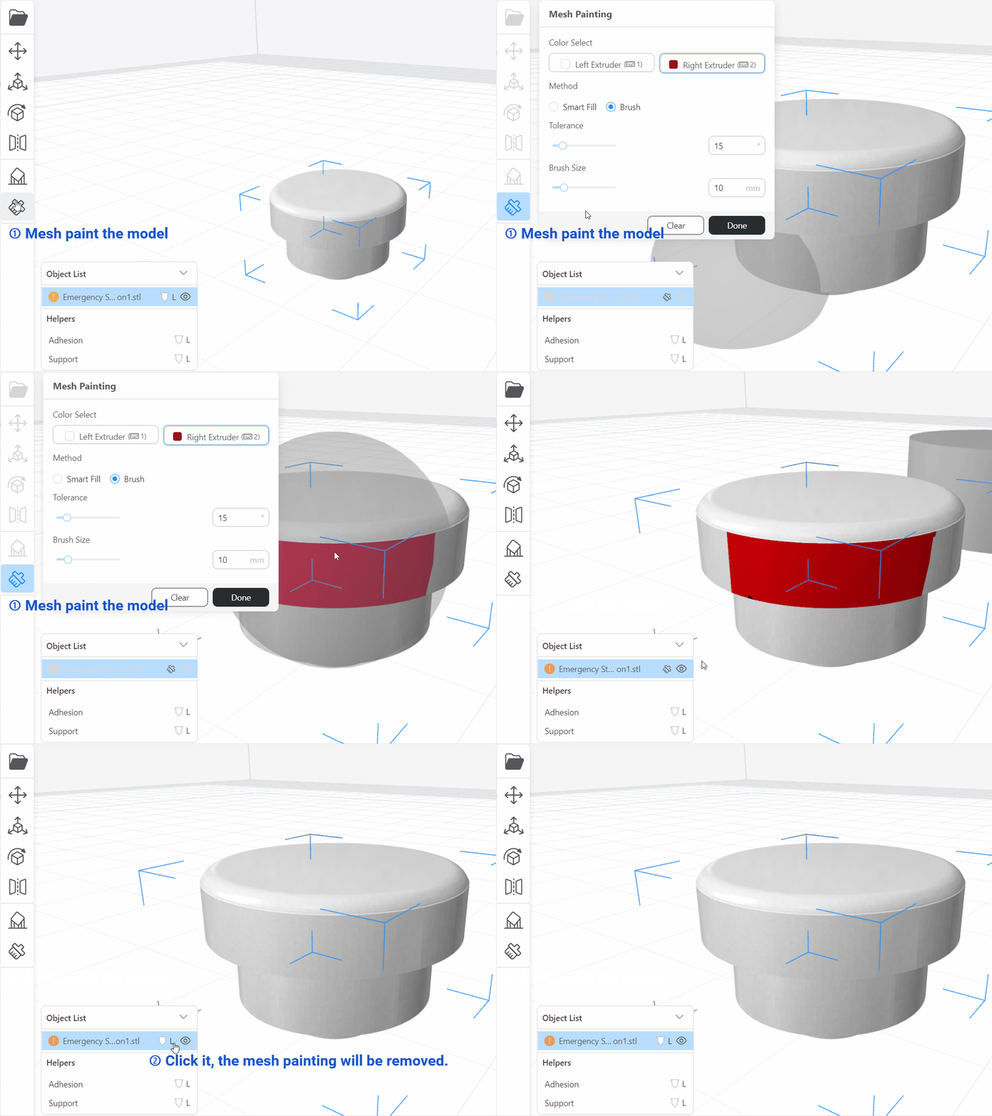
In object list, there is the "Quick Clear Mesh Painting" tool, you can use it to quickly remove or reset the mesh painting effects.

Only when you have applied mesh painting operation to an object, this tool is available.
