¶ 💡 Compatibility
This article applies to the following models and modules. Please note when referring to it:
Model: U1
¶ 📋 Quick Info Card
-
Difficulty: ⭐⭐⭐☆☆ (Medium)
-
Estimated Time: 30 minutes
¶ 🧰 Preparation
- Enable Advanced Mode
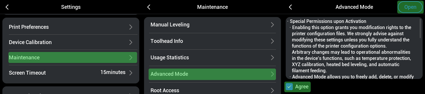
If you are only referring to this article to calibrate XY coordinates, enabling Advanced Mode does not affect your machine's warranty.
- Connect your computer and the machine to the same Wi-Fi network
¶ 🛠️ Procedure
Toolhead Pick & Park Principle
¶ 1. How is the toolhead pick & park position determined?
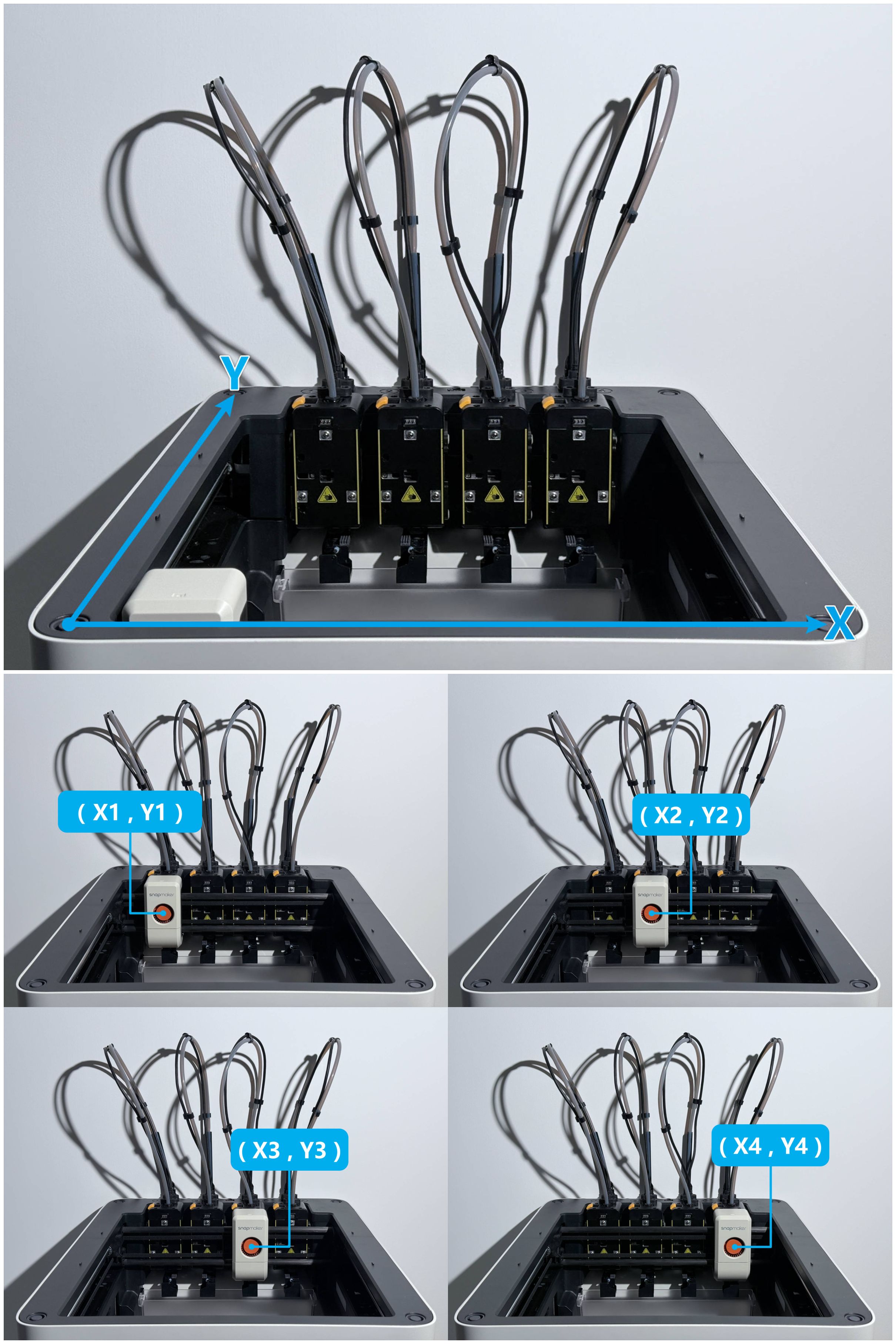
After homing complete, an X—Y coordinate system is generated on the current horizontal plane;
When picking each toolhead, toolhead swapper moves to the corresponding coordinate position.
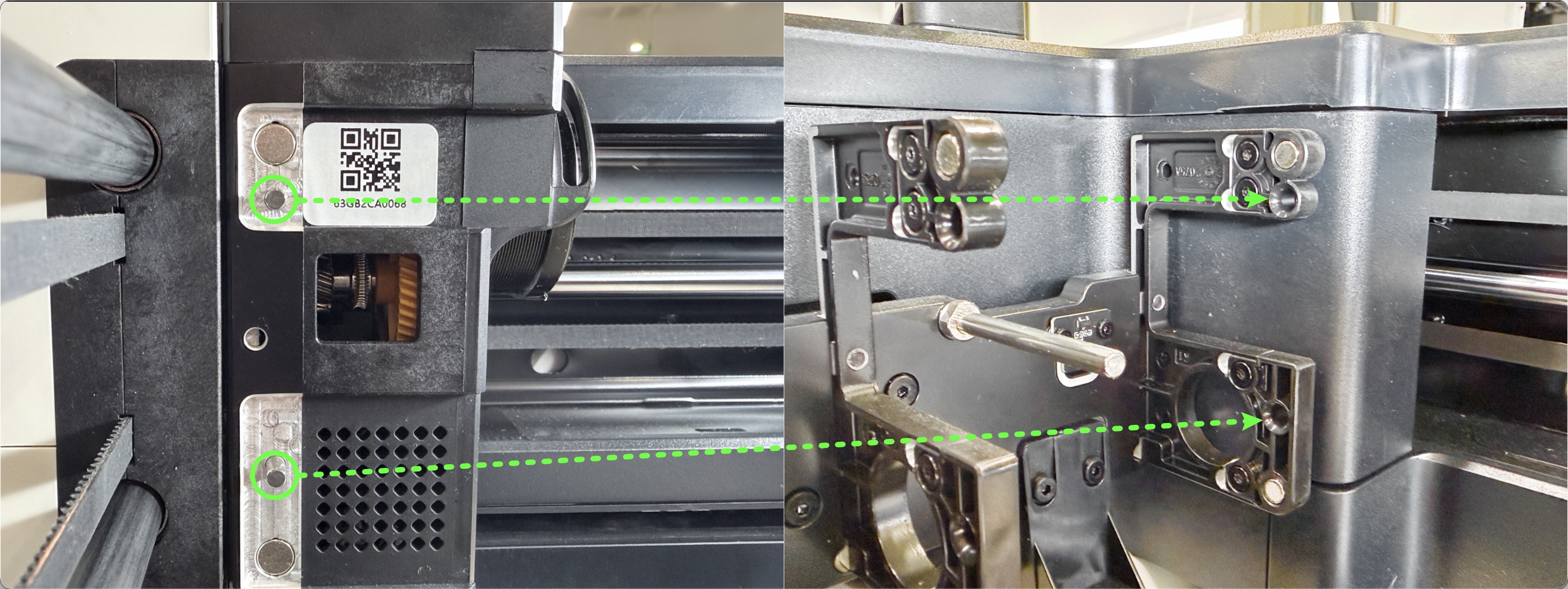
¶ 2. How does the swapper lock the toolhead?
After moving to the pick & park coordinate, the swapper moves left/right, engaging the pull pin with the pull bolt to lock it, and finally moves outward to attach the toolhead.
¶ 3. Parking the toolhead
This is performed by executing the above steps in reverse.
Where are the pick & park coordinates?
How to calibrate the X coordinate?
In the Settings — Maintenance menu on the screen, follow the on-screen prompts to perform Homing calibration.
How to calibrate the Y coordinate?
Before calibrating the Y coordinate, you must first calibrate the X coordinate.
¶ Calibration Reference
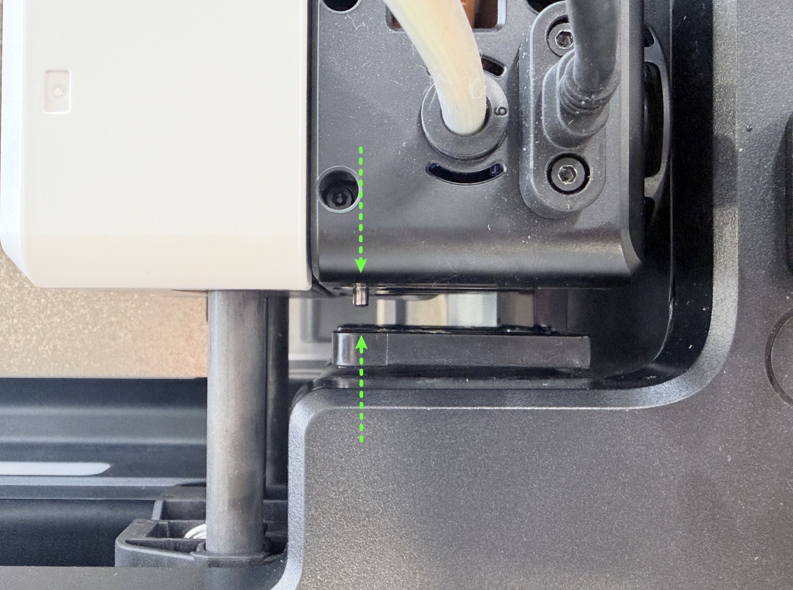
With the toolhead in attached state, move the swapper so that the side pin of the toolhead is centered and aligned with the docking slot of the parking bracket.
The Y coordinate at this position is the calibrated value.
¶ Calibration steps
¶ 1. Home the machine
Enter the machine's IP address in your browser to access Fluidd, then click Dashboard — Extruder — Home XY in sequence.
¶ 2. Begin calibration
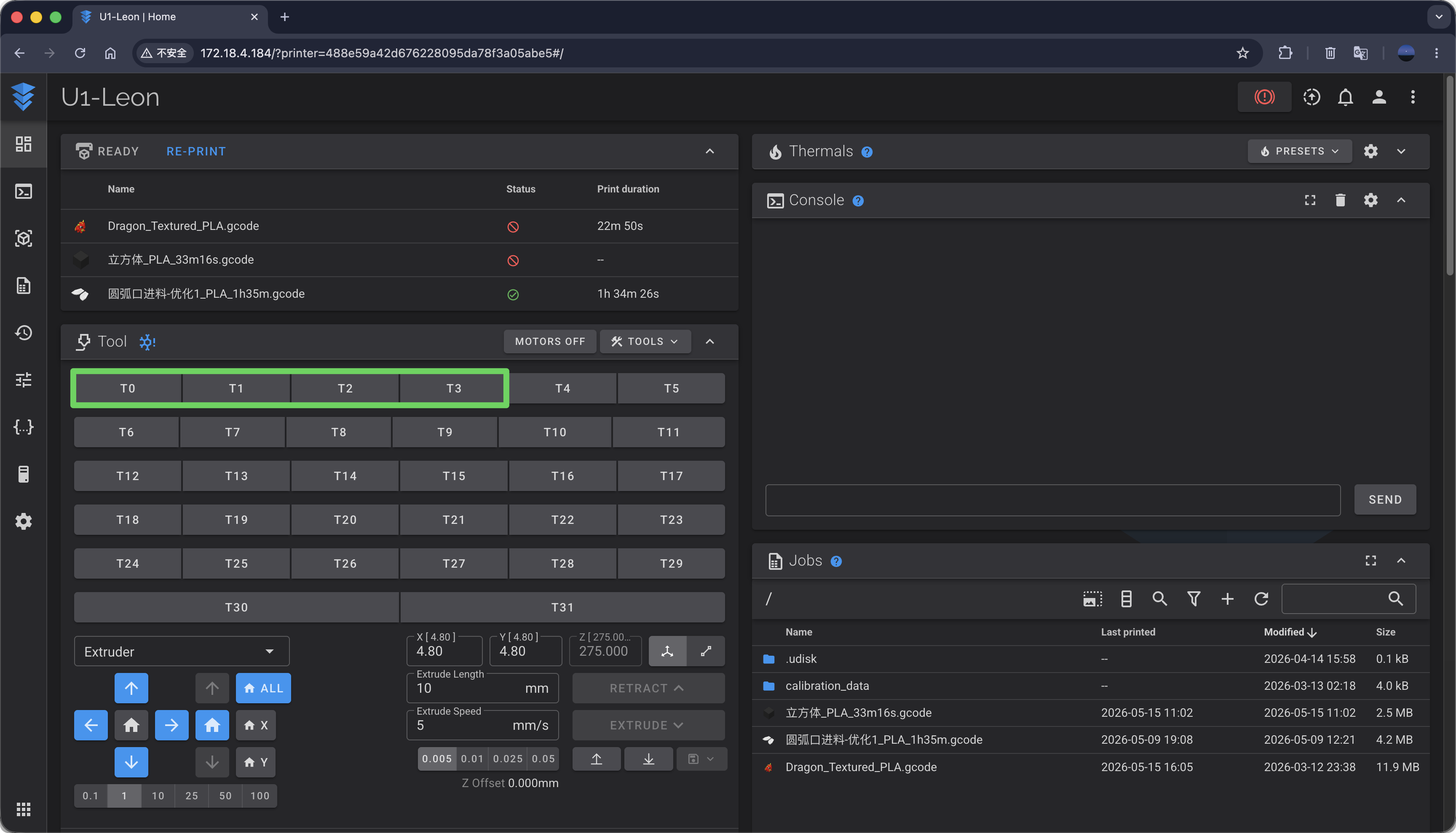
Use the T0, T1, T2, T3 macro functions to pick the problematic toolhead. These 4 macros correspond to picking Toolhead 1, 2, 3, and 4 respectively;
Taking Toolhead 2 as an example, click T1, and the machine will pick Toolhead 2.
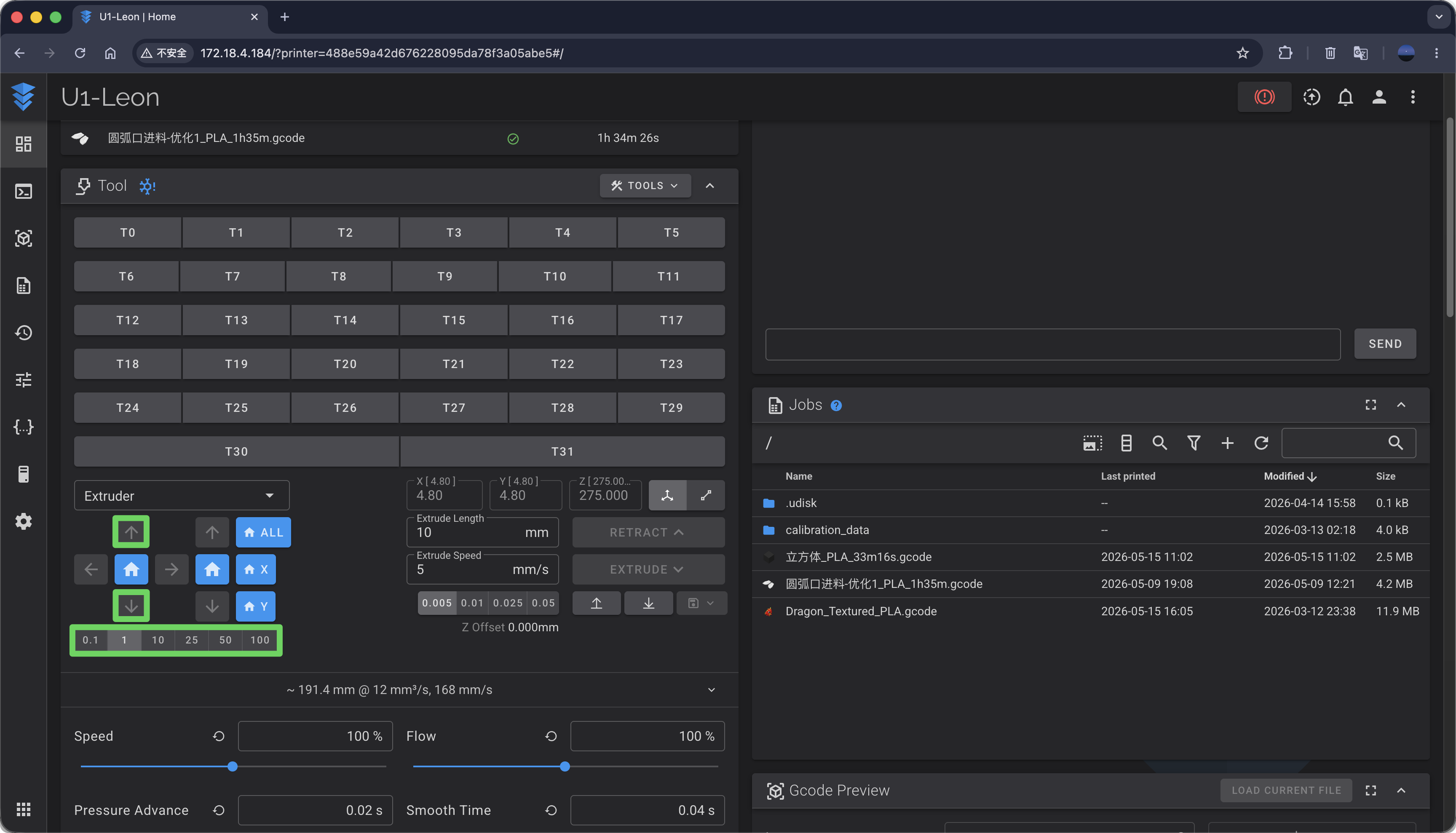
Using the movement tool in the lower-left corner, select an appropriate step size and move the swapper forward or backward until the swapper and toolhead reaches the reference position shown in Calibration Reference;
For example: Select step size 1 and click the ⬆️ arrow key, and the swapper & toolhead will move backward by 1mm.
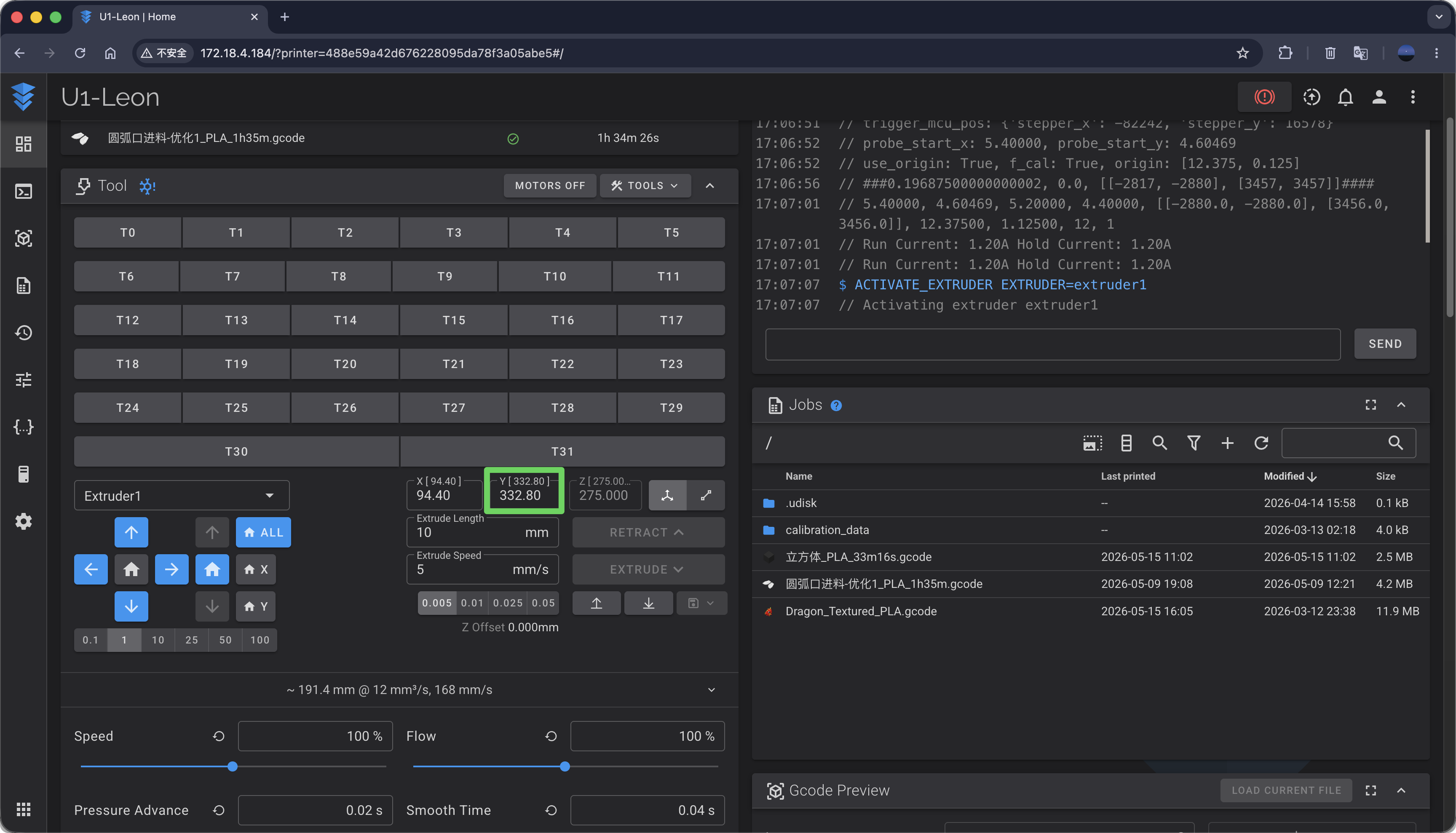
At the reference position, the value displayed in the Y coordinate input box is the calibrated Y coordinate.
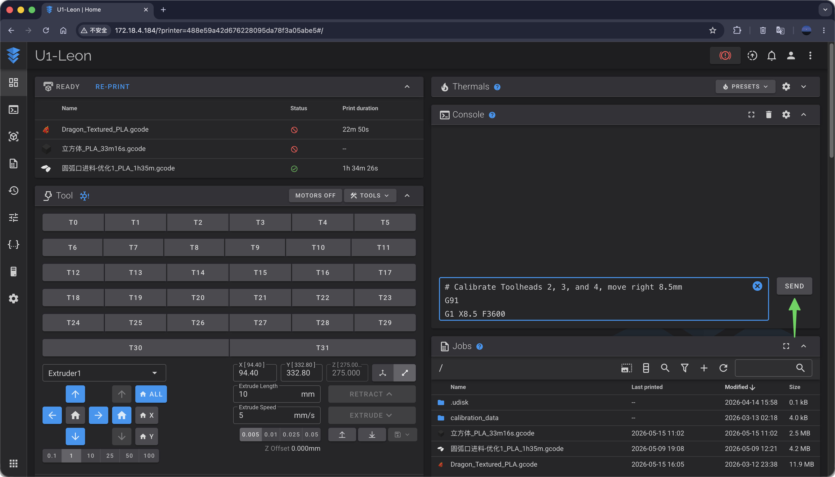
¶ 3. Coordinate Verification
At the reference position, try moving the swapper & toolhead left or right to park the toolhead. Depending on the specific case, enter the following commands in the console:
# Calibrate Toolhead 1, move left 8.5mm
G91
G1 X-8.5 F3600
# Calibrate Toolheads 2, 3, and 4, move right 8.5mm
G91
G1 X8.5 F3600
If the side pin of the toolhead slides smoothly into the docking slot of the parking bracket, your calibrated Y coordinate is correct.
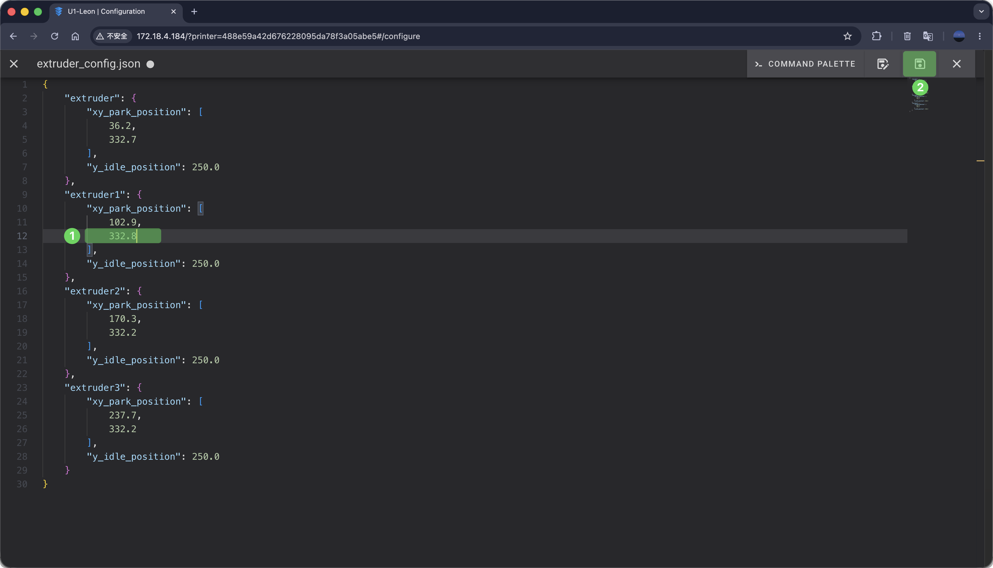
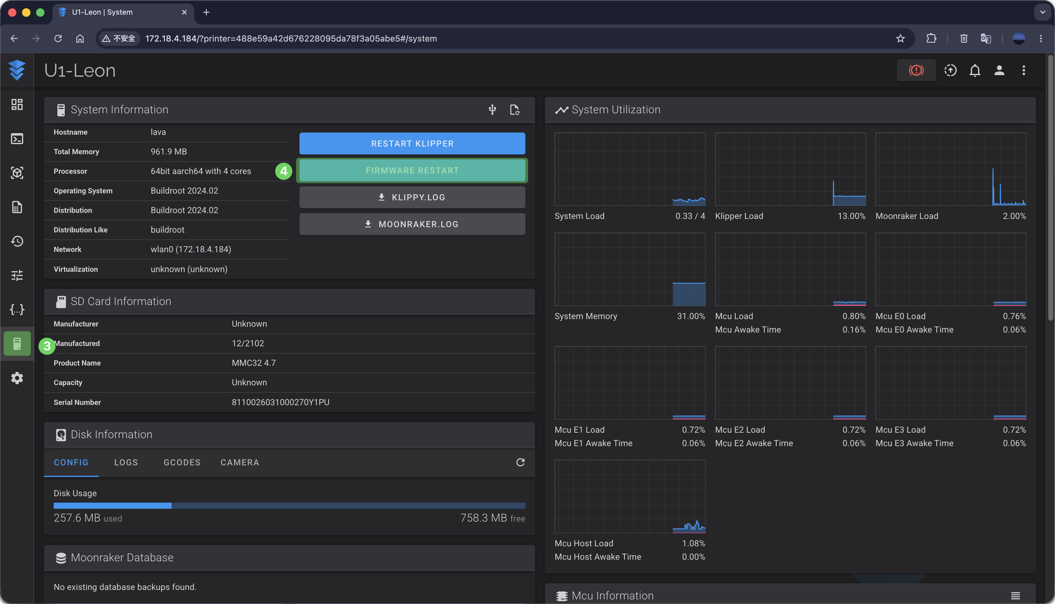
¶ 4. Update the Coordinates
Update the calibrated coordinates in the corresponding location in extruder_config.json, save and exit, and restart the firmware to apply the changes.
Common Issues During Calibration
¶ Toolhead Falls Off
When the Y coordinate is too small, the swapper cannot lock toolhead due to excessive clearance;
You can try increasing the Y coordinate for this toolhead in extruder_config.json.
¶ Toolhead Collision
Restart the machine and perform the calibration again, making sure to strictly follow the instructions.