This guide is applicable to standard situations, where stock hot build plate is used with stock firmware, recommended slicer. And common, consumer, filament types. If your setup differs from standard/recommended - please use instructions provided by the manufacturer of the 3rd party item (cold plate, advanced filament, modded firmware, etc).
¶ Quick Diagnosis
You can quickly find the corresponding section for the specific first-layer print issue you’re encountering by using the links below. We recommend reading the entire article for the best results.
- "Pre-flight" checks
- FIRST LAYER DOESN'T STICK TO THE BUILD PLATE
- WRINKLES IN THE FIRST LAYER
- GAPS BETWEEN LINES OF THE FIRST LAYER
- Other Special Cases
¶ "Pre-flight" checks
Many issues with first layer have the same underlying causes. Let's take care of these first, and then dive deeper into specifics with some failure examples and relevant actions to take.
Common issues responsible for >90% of the problematic first layer (in order of occurrence) are listed below. Cross them off before going to a detailed section of this guide.
¶ Build plate surface cleanliness
- So much as a fingerprint in a wrong spot can cause bad adhesion for the first layer. The safest way to clean your build plate: dish soap. Wash it as a dish, by hand, minimize water contact to prevent rust. Dry it with a clean, lint-free cloth before installing it into the printer.
- Consider using dish soap over isopropyl alcohol as a universal and safe method to clean build plates. Isopropil alcohol is highly flammable and can be toxic if ingested or absorbed through the skin, leading to symptoms like dizziness, nausea, and central nervous system depression. Not all build surfaces are safe to clean with Isopropil alcohol.
¶ Bed leveling / Z-offset incorrect
-
Moving around the build plate, flipping it upside down, and removing objects from the hot build plate (always wait until it's cooled down) can change the surface of the build plate to the point that it would not match the saved, in-printer leveling information.
-
Make sure there is no debris between the build plate and the heated bed.
-
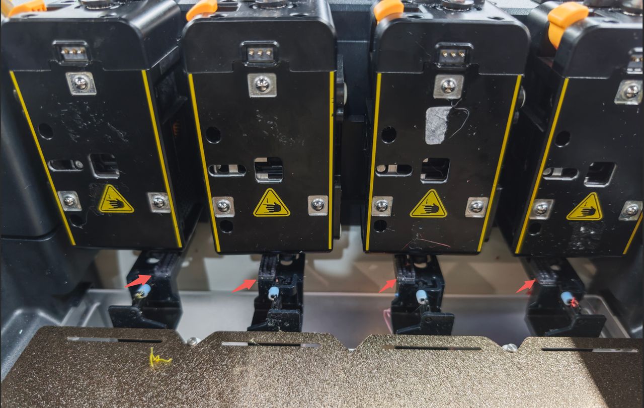
Check whether the silicone wiper on the nozzle cleaning bracket is damaged or detached. Replace as needed.
-
Check your nozzle for buildup before cleaning it with the included brush - heat it up to 200°C for PLA and 230°C for ABS.
-
Run the automatic bed leveling procedure to create a fresh mesh. On the screen of the printer, go to Settings > Device Calibration, toggle Heated Bed Leveling and tap the start button in the upper right corner.
¶ Filament quality compromised
- Wet filament is the biggest issue here. Trapped moisture will boil and cause bubbles to pop at the nozzle exit. Increased stringing is another sign. This will cause unwanted artifacts to appear on the build plate - blobs of plastic, strings dragging across. Sometimes the nozzle can drag across one of those blobs and ruin the first layer altogether. If you can snap off a piece of filament with your fingers by bending it, it is likely wet.
- Make sure to use a fresh batch of dry, not brittle, filament. Use filament manufacturer recommendations to dry the filament in a heated filament dryer if necessary.
- Finally, load the filament, bring the relevant extruder up to working temperature, and run the extrusion command, to see the smooth and uniform filament flow.
¶ Completing the pre-flight check
It is much faster to use a small object created in slicer to test your first layer. This will allow you to remove all the variables that a 3D model might bring with it, and help with further troubleshooting.

In slicer, add a primitive box, reduce it to a 0.2mm layer, select the appropriate profile for quality/filament, and run a test with it. If the issues are resolved, great! Keep on making wonderful things. If the issue is still there, or appears again with the model, use the information below for further troubleshooting.
¶ DEEPER DIVE INTO TROUBLESHOOTING THE FIRST LAYER ISSUES
Assuming all of the above steps didn't fix issues with the first layer, use following information to troubleshoot further.
¶ FIRST LAYER DOESN'T STICK TO THE BUILD PLATE
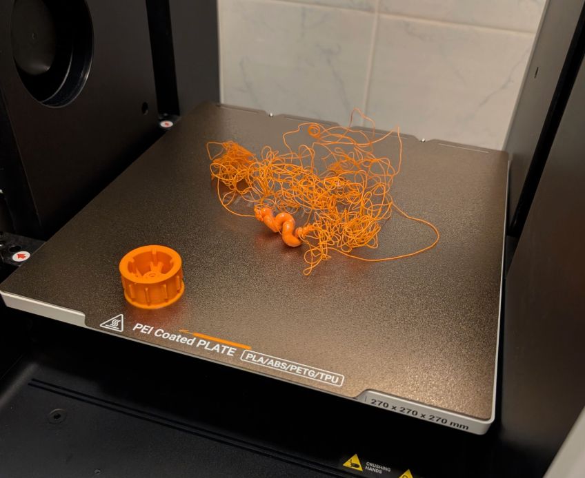
Sometimes you get a blob of plastic at the nozzle, or a model breaks off from the build plate and the printer starts printing mid-air. Result: a print that can be passed as art, sometimes. Nevertheless, it is a failed print; let's make it work.
¶ Insufficient contact area between the build plate and the model.
Sometimes, the model itself can be designed in a way that is not optimized for 3D printing. Use information below to mitigate this.
- Some models require supports to stay put on the build plate. This is especially important for tall models with a small footprint. Growing up, tall and thin print becomes increasingly sensitive to the nozzle movements. And can break away from the build plate. Use the Brim or Supports Painting tool in the slicer to add Hybrid Tree Supports to stabilize the model on the build plate.
- Some models, especially those generated with AI tools, prone to having a bad bottom surface. The model in the image below has such issue - the bottom surface is very uneven, and not allowing good contact with the build plate. The Lay on Face tool is used in the slicer to highlight available surfaces.
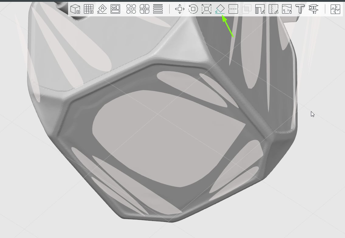
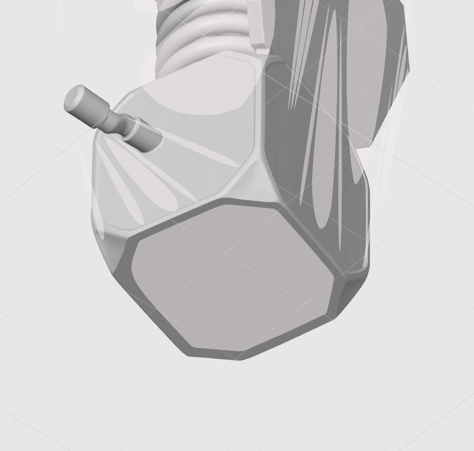
This can be adjusted by lowering the position of the model, slightly below the surface of the build plate in the slicer. Cutting off the uneven bottom surface in the process. Or slicing the bottom of the model using the Cut tool in the slicer. The image below has the same model but a fixed bottom surface.
¶ Improper slicing parameters
As mentioned above in Insufficient contact area between build plate and the model section, some models are not designed wit 3D printing in mind. Use following slicer settings to help a print succeed.
-
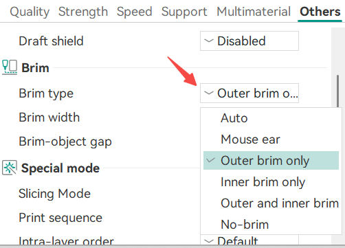
Adding a brim to the model helps with stability.
-
For small or complex models, orientation of the model can be adjusted to increase the surface area that touches the build plate.
-
Sometimes, increasing bed temperature for the first layer can yield improved results.
-
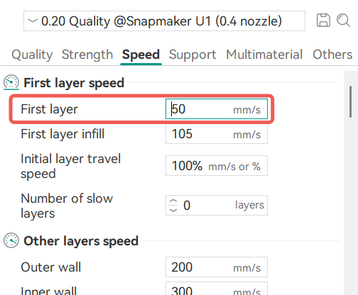
Adjusting these first-layer parameters is another option to try and solve the issue:
¶ Issues affecting bed leveling procedure
There are some factors that can affect the accuracy of the bed leveling related to the load cell condition in an toolhead.
It is recommended to perform the checks on two toolheads, so called "1+1 Check Method". All toolheads rely on calibration data coming from the left most toolhead (#1). If you don't find an issue with toolhead that experiencing problems (#2, #3 or #4) - check toolhead #1.
-
Make sure the two hotend mounting screws are fully tightened.
-
Make sure there is no debris between the heatsink fins and the copper sensing plate.
-
Verify there is sufficient clearance between the heatsink fins and the copper plate to allow deformation during calibration.

Some issues can be resolved with Manual bed leveling procedure.
- Go to Settings > Maintenance > Manual Leveling and follow the prompts on the screen to adjust the heated bed position.
- After manual leveling, run automatic bed calibration; go to Settings > Device Calibration, toggle Heated Bed Leveling and tap the start button in the upper right corner.
- Test the first layer print.
Please print the manual leveling assistant tool (designed by Simon_Zhi) in an area where the first layer prints well, so you can make adjustments more easily instead of using your hands directly.
¶ Worn or poor-quality PEI coating
- PEI build plates can wear out with print time accumulating. Inspect your build plate for damages, pulled surfaces, bumps, and craters. Flip the build plate to use the fresh side.
¶ WRINKLES IN THE FIRST LAYER
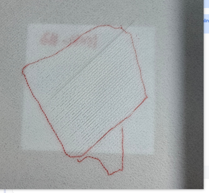
Excessive overlap between adjacent layer lines can cause waves, wrinkles, or filament buildup. If the affected area exceeds 10 percent of the total printed area, the first layer is considered unacceptable. Use information in this section to troubleshoot the issue.
To check for small/large area wrinkles - run a test print, using primitive described in COMPLETING THE PRE-FLIGHT CHECK. Scale the primitive in X & Y axis to completly cover the build plate.
¶ Large area wrinkles
If you are experiancing small area wrinkles, skip this section and start from Debris between heated bed and build plate below.
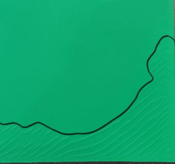
- Large-area wrinkles are usually caused by the Z offset being set too high, resulting in the nozzle being too close to the platform.
- Use Adjust Z-offset in the Klipper configuration file section to access the print.cfg via the Fluidd interface.
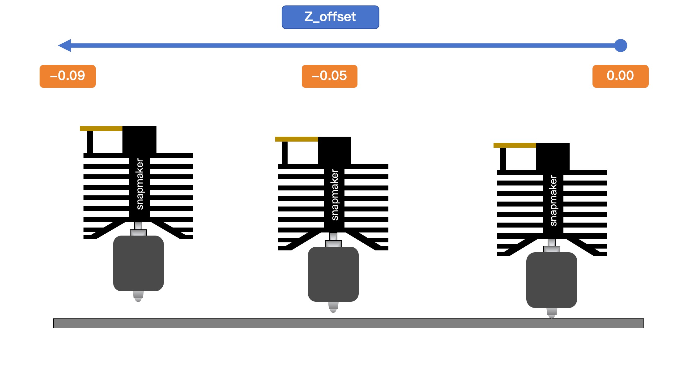
- Gradually decrease the Z-offset value, for example: -0.05 to -0.07 to -0.09. Avoid large increments.
- A smaller Z-offset value, moves the nozzle away from the build surface. E.g., increase the nozzle-to-build plate distance.
¶ Debris between heated bed and build plate
Refer to Bed leveling / Z-offset incorrect section.
¶ Build plate flatness
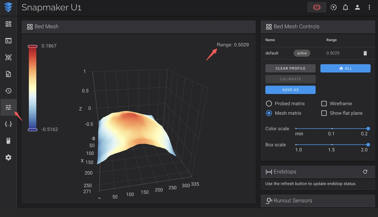
Check the RANGE number in Fluidd (printer's user interface availible via web browser). It indicates the height difference between the highest and lowest points on the build plate. Range under 0.5mm considered normal.
-
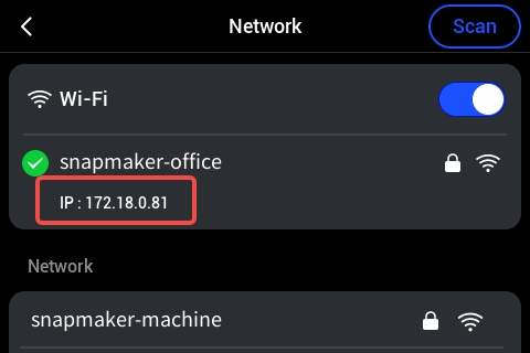
Get the printer's IP address, by going to Settings > WIFI. IP address is written as a sequence of numbers separated with dots. The screenshot below has is as 172.18.0.81.
-
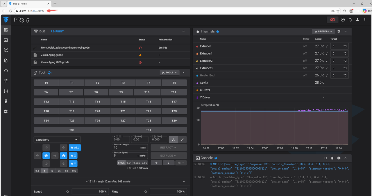
Use the IP address of the printer in a web browser to access the Fluidd interface.
-
In the sidebar on the left, select Tune (t) to view the mesh data.
-
Check for the Range number in the upper right corner. If it is under 0.5mm - no further action is needed. Otherwise, proceed as described below.
-
If wrinkles align with mesh peaks (red colored areas). Check if heated bed (under the build plate) has excessive glue or bumps around the magnets.
-
If the Range exceeds 0.8mm, and raised corners align with wrinkles, perform Manual bed leveling. On the printer's screen, go to Settings > Maintenance > Manual Leveling and follow the prompts on the screen to adjust the heated bed position.
-
After manual leveling, run automatic bed calibration; go to Settings > Device Calibration, toggle Heated Bed Leveling and tap the start button in the upper right corner.
-
If the issue persists, flip the cleaned PEI sheet to use the other side, and repeat the steps of this section.
¶ Adjust Z-offset in Klipper configuration file
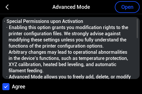
Please first enable Advanced Mode on the screen by going to Settings > Maintenance > Advanced Mode. If you are doing this under the guidance of Snapmaker Support, it will not affect your warranty, so you can proceed safely.
-
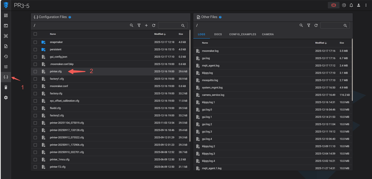
In the Fluidd interface, in the left sidebar, select the Configuration x menu item.
-
In the left panel, showing a list of files, find and open the file named printer.cfg.
-
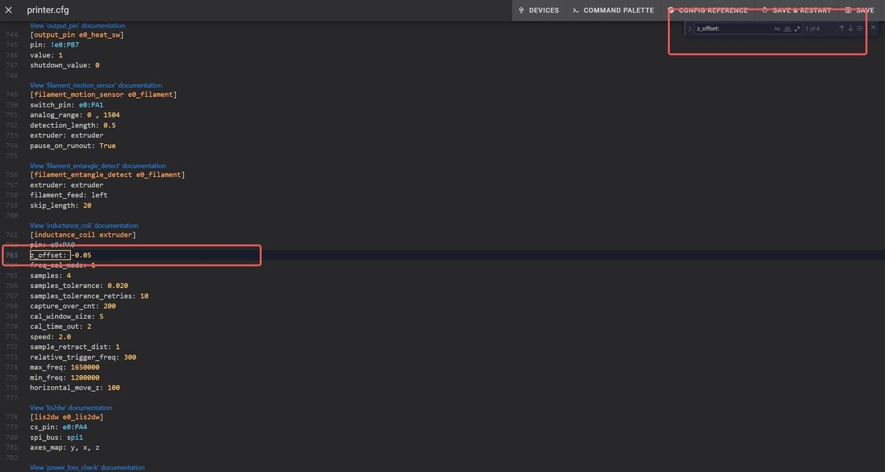
Inside, find parameter Z_offset and adjust it gradually, with steps no more then 0.05mm at a time.
-
Save the changes, power cycle the printer, and try the first layer. If printed first-layer symptoms became worse, change the number in a different direction (for example, if you went from -0.10 to -0.15, going in different direction would mean going to -0.05). If symptoms become better, keep dialing or keep the changes made as is.
¶ Heat soak the bed before printing
- Heat up the bed to 65°C for at lest 5min before starting the print. If this reduces the wrinkles, the issue may be related to restricted bed deformation caused by the plastic bed bed shell (covering the bottom and sides of the heated bed).
¶ GAPS BETWEEN LINES OF THE FIRST LAYER
When nozzle is too far from the build plate, visible gaps appear between first-layer lines. Little or no overlap between lines, resulting in translucent, sparse, or broken lines. If the affected area exceeds 10 percent of the total print area, the first layer is unacceptable.
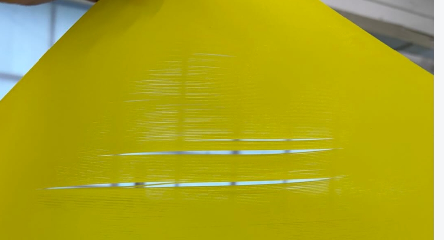
To check if the issue is localized or affects full build surface - run a test print, using primitive described in COMPLETING THE PRE-FLIGHT CHECK. Scale the primitive in X & Y axis to completly cover the build plate.
¶ Small area affected with gaps issue
- Refer to the WRINKLES IN THE FIRST LAYER section; the large area subsection is not applicable, see below if a large area is affected.
- Refer to Adjust Z-offset in the Klipper configuration file and change the Z-offset value in small increments to bring the nozzle closer to the build plate. For example, values will be changed from -0.05 to -0.03 to -0.01 and so on.
¶ OTHER SPECIAL CASES
¶ Issue appears only with one of the toolheads
After calibrating a specific toolhead, the first layer fails or appears uneven.
- Refer to the Issues Affecting Bed Leveling Procedure section, for toolhead troubleshooting.
¶ Issue appears on many toolheads, but at least one toolhead has no issues
At least one toolhead prints the first layer correctly, while (two or more) others fail.
- Run the Multi-toolhead Offset Calibration. Using the printer's screen, navigate to Settings > Device Calibration > Multi-toolhead Offset Calibration. Follow the prompts on the screen.
- If the issue persists, calibrate and test each toolhead individually.
¶ Different filament types behave differently
When PLA prints the first layer successfully, but PETG or other filaments fail. Higher bed temperatures require more time to stabilize.
- Check if the correct filament profile is selected for the printed part.
- Heat soak the bed for 5 mins before starting the print.