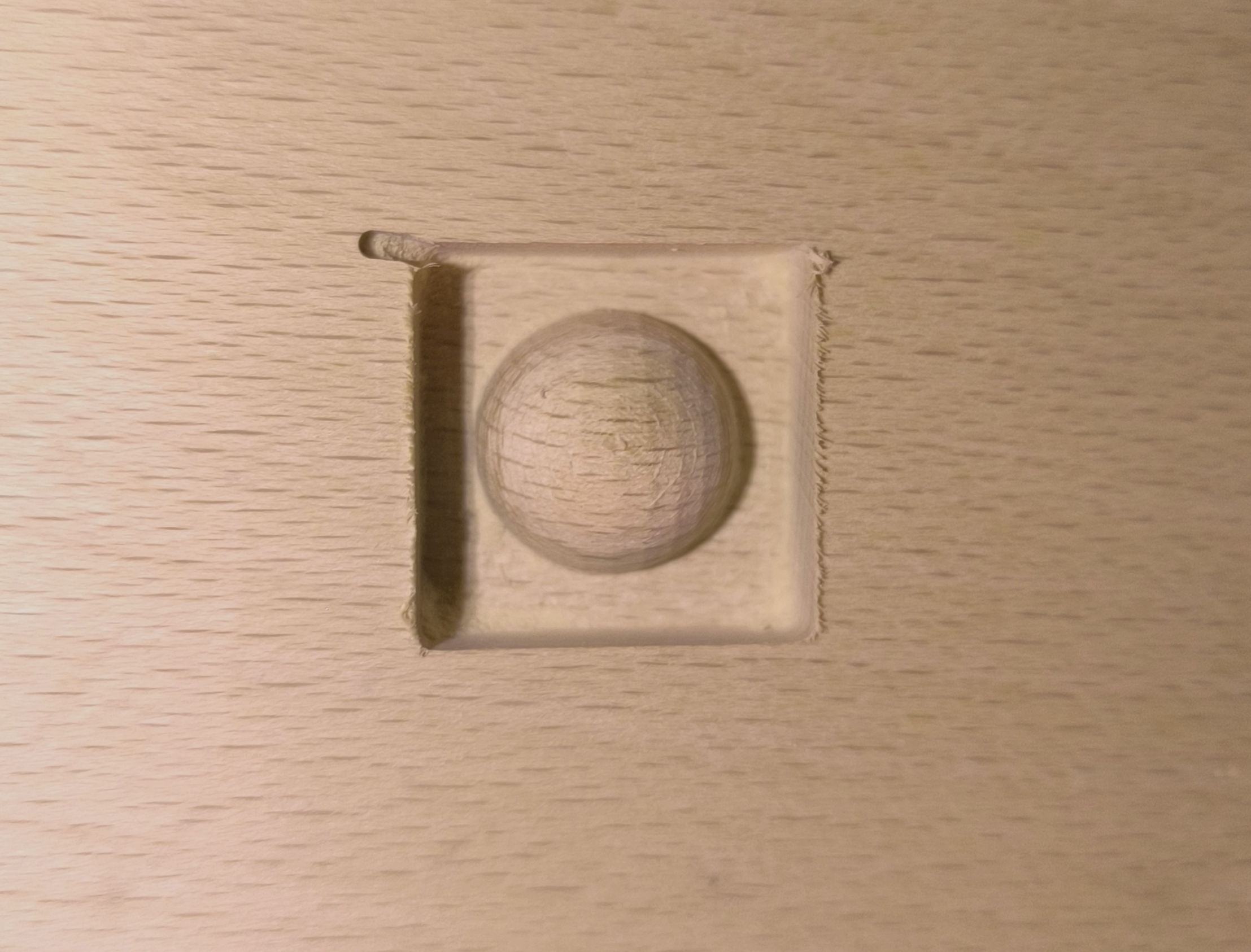
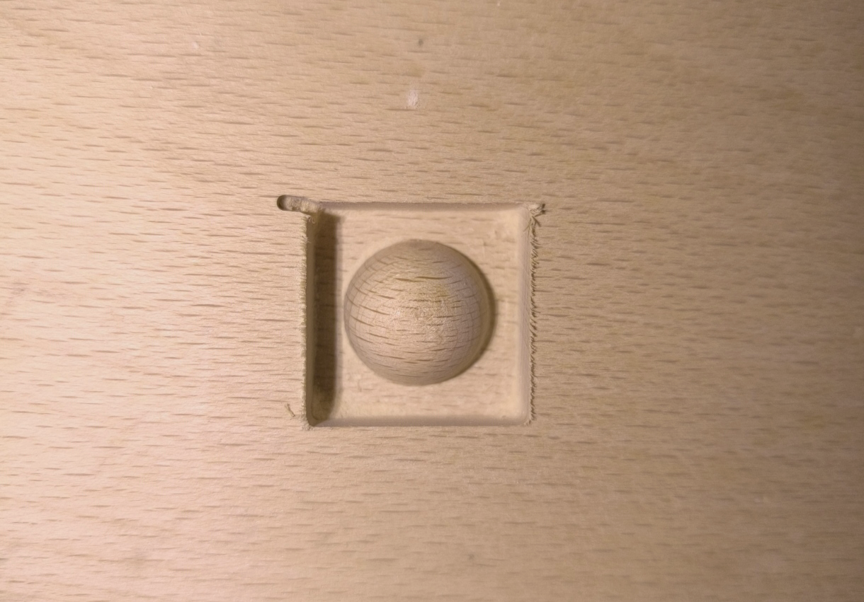
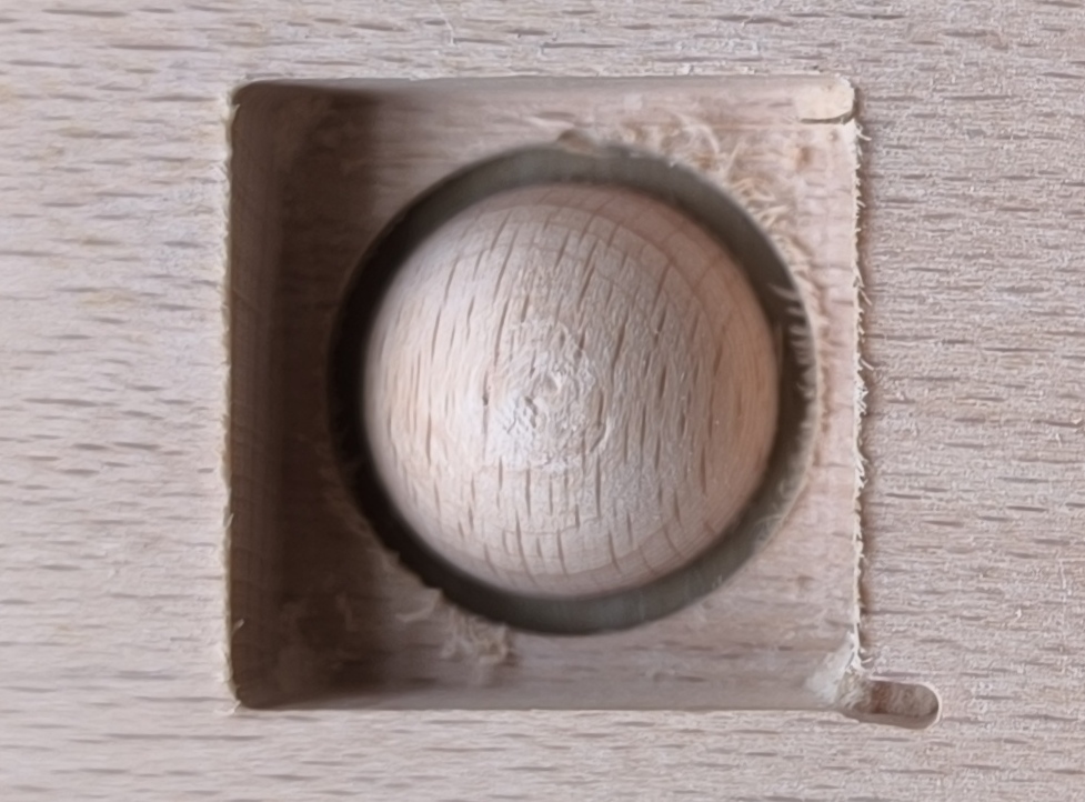
In most cases, it is recommended to use multiple processes, e.g., roughing and finishing, to enhance machining efficiency in creating detailed reliefs.
¶ 01 Before You Start
Download the latest version of Fusion 360 from its official website and install it on your computer.
-Autodesk Fusion 360 is now renamed as "Autodesk Fusion", which drops the "360" from the name.
-There is a 30-day free trial available for new users of Fusion 360, and you can access Fusion 360 Education Version if you are a student or teacher.
¶ 02 Tools & Accessories Required
In this article, to illustrate how to use Artisan/2.0 with Fusion 360 for multi-process 3-axis CNC machining, we will walk you through a simple project (cutting a half-sphere with CNC), which mainly includes three processes: roughing, finishing and 2D contour. In the roughing phase, large cutting tools are employed to remove the majority of the material, leaving a small amount as an allowance for later steps. This phase quickly clears out excess material and shapes the basic form of the object. Following this, the finishing phase uses more precise tools to refine the details and achieve a high-quality surface finish. The finishing pass typically has zero allowance and is performed once to ensure accuracy and detail without overcutting.
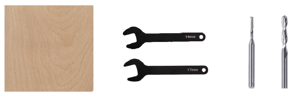
During machining, you will need the tools and materials listed below.
The height of the beech should be larger than the radius of the sphere (10mm), otherwise the CNC bit would crash into the CNC carving and cutting platform during machining.
- Beech ×1 (the height is 12mm)
- 14mm open end wrench ×1
- 17mm open end wrench ×1
- 1.5mm flat end mill ×1
- 3.175mm ball end mill ×1
¶ 03 Procedures
The following flowchart outlines the procedures to use Artisan/2.0 with Fusion 360 for multi-process 3-axis CNC machining:
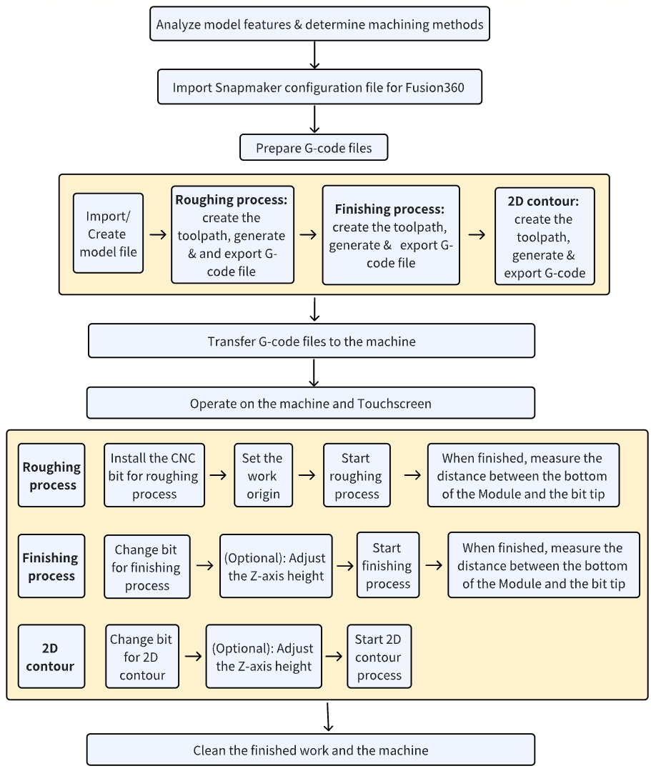
¶ 3.1 Analyze model features & determine machining methods
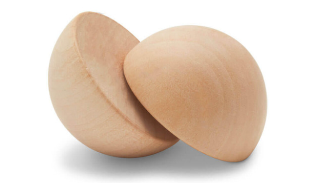
To cut a beautiful half sphere out of a piece of wood, we need:
- Perform a 3D roughing method, e.g., Adaptive Clearing, to quickly remove the large amount of material from the surface.
The bit we will use in this step is a 1.5mm flat end mill.
For 3D Adaptive Clearing method, Fusion 360 doesn't provide the tabs setting. Therefore, to hold the half sphere in place during final cutting, it's advised to leave the bottom materials uncut.
- Perform a 3D finishing process, e.g., Spiral, to smooth the surface.
The bit we will use in this step is a 3.175mm ball end mill.
- Considering that after roughing and finishing processes, the half sphere model is still attached to the material, so we need to adopt a 2D contour method to separate the half sphere and the material.
The bit we will use in this step is a 1.5mm flat end mill.
¶ 3.2 Import Snapmaker configuration files into Fusion 360
- Download Snapmaker configuration files for Fusion 360 from here.
- Unzip and open the downloaded file, copy the Fusion folder to Users > Username > AppData > Roaming > Autodesk > CAM 360 > libraries > Local.

¶ 3.3 Prepare G-code files
¶ Import/Create model file
Fusion 360 supports model files in various formats, such as .dxf, .fbx, .iges, .obj, .nx, .step, .stl, etc.
To create your own model files, click File button > New Design on the top left navigation bar.
PLease note: The radius of the half sphere is 10mm, make sure you have prepared a beech whose height is bigger than 10mm.
- On the top left navigation bar, click Open.

- On the pop up window, click Open from my computer.
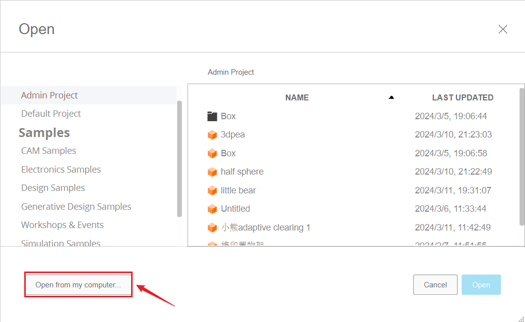
- Select half-sphere.step file and click Open.

¶ Roughing process
¶ Create the new setup
In this section, you need to set the work origin and stock mode for the model.
- Switch to MANUFACTURE workspace in Fusion 360.
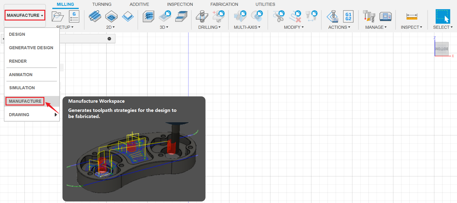
- On the MANUFACTURE workspace toolbar, click Setup > New Setup.

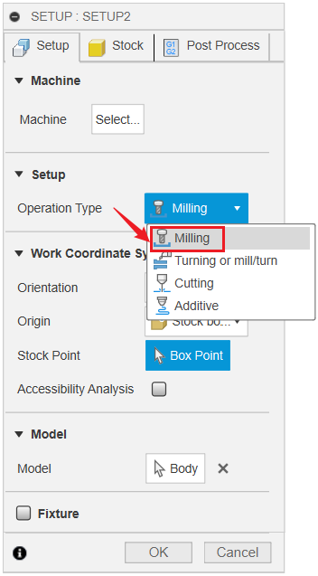
- In the pop up window, select Milling for Operation Type.
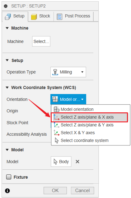
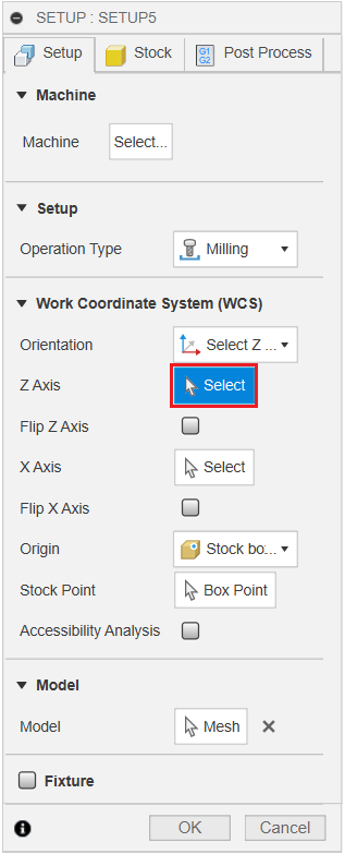
- Select Select Z axis/plane & X axis for Orientation. Then click Select.
- Click the current origin, then click center point so as to set the origin at the center point.
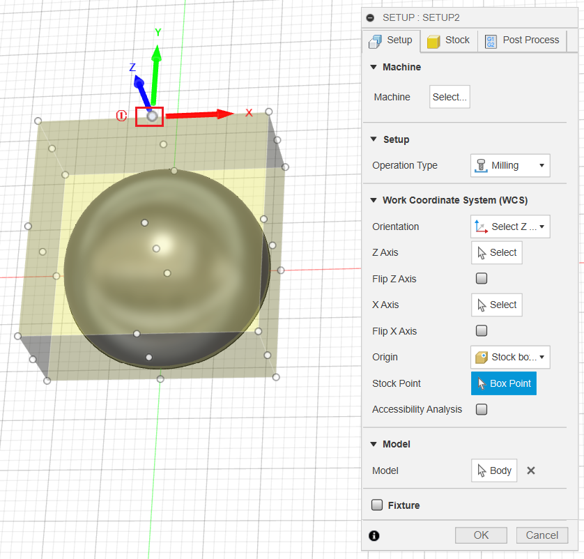
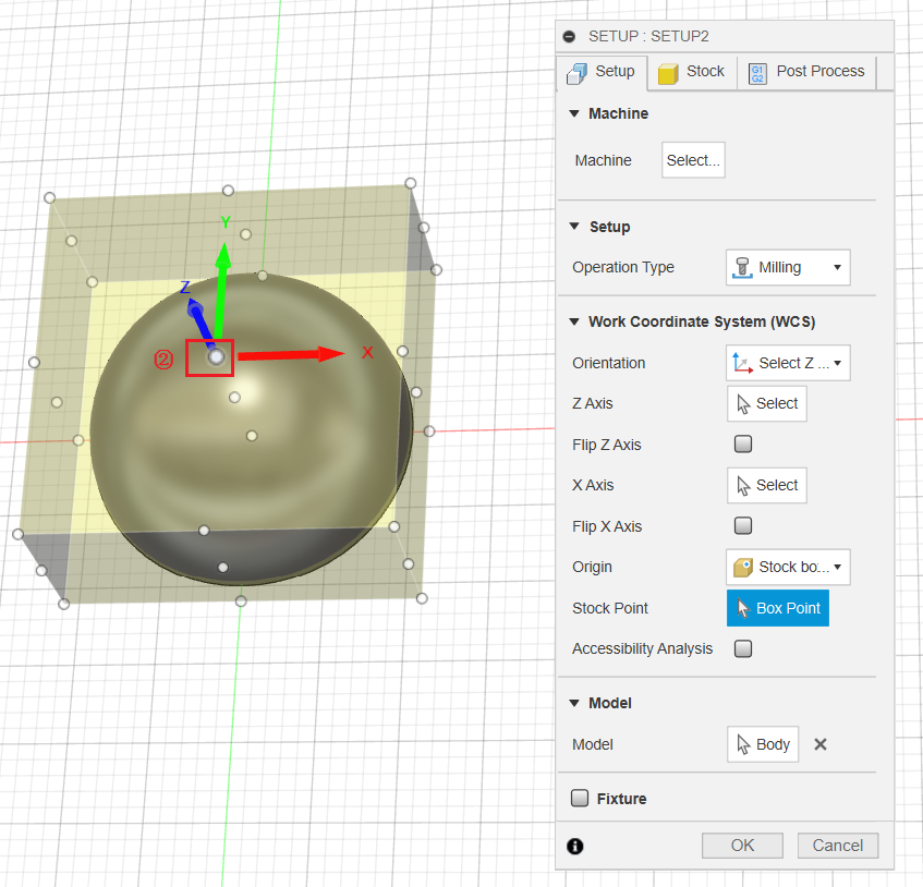
Make sure that the Z-axis is facing up.
Do not click OK, since there are other SETUP you need to do in the following steps.
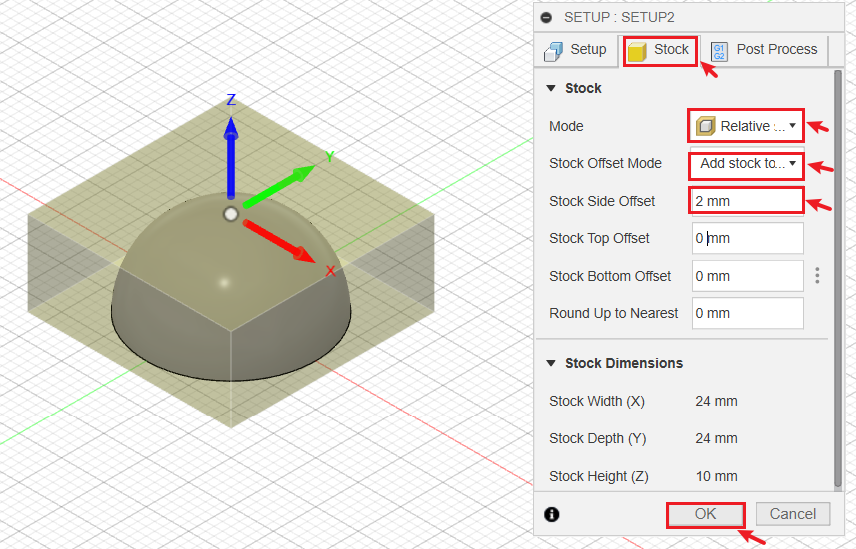
- Switch to Stock tag. Set Mode to Relative size box, set Stock Offset Mode to Add stock to sides and top-bottom; then set Stock Side Offset to 2mm. Click OK when finished.
¶ Create the toolpath
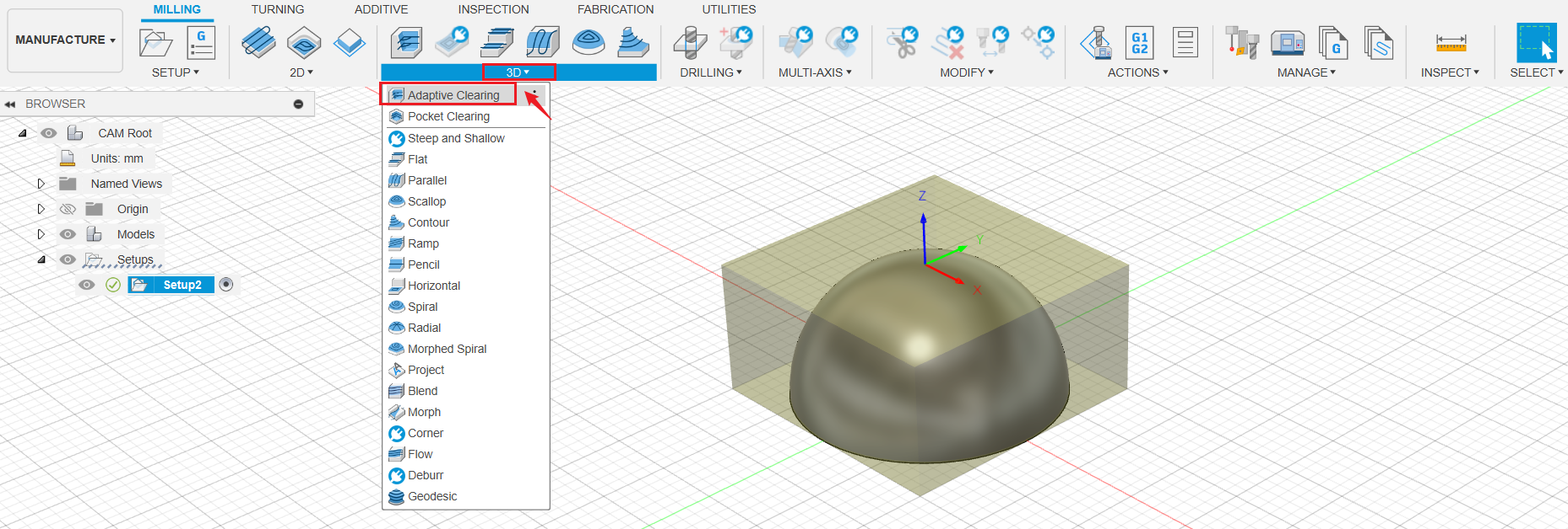
- Click 3D > Adaptive Clearing.
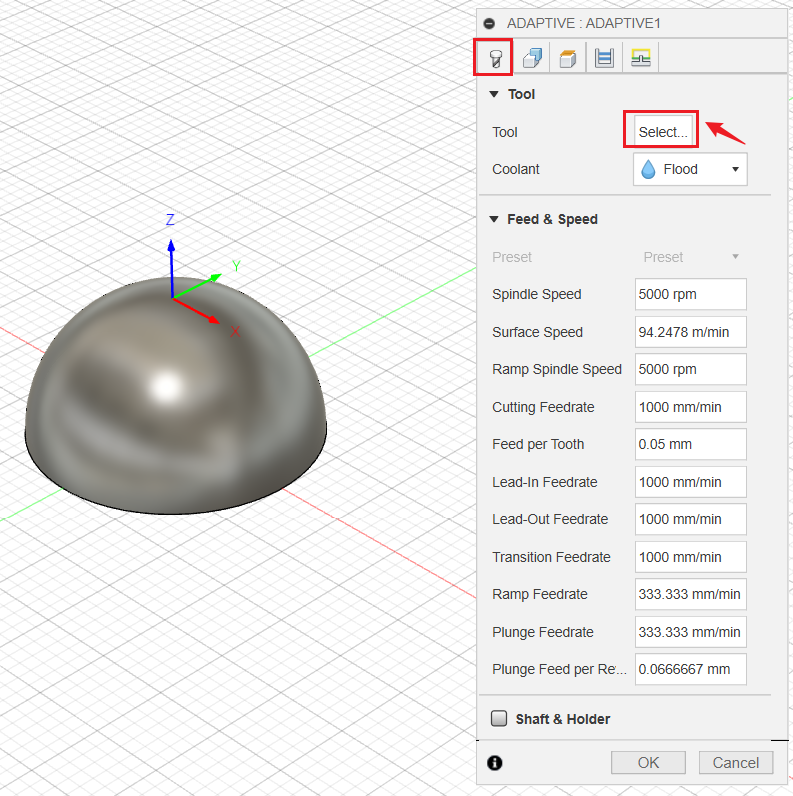
- Under Tools tag, click Select.
If you are using Fusion 360 with Snapmaker machines for the first time, you need to import the Snapmaker tools library into Fusion 360 first.
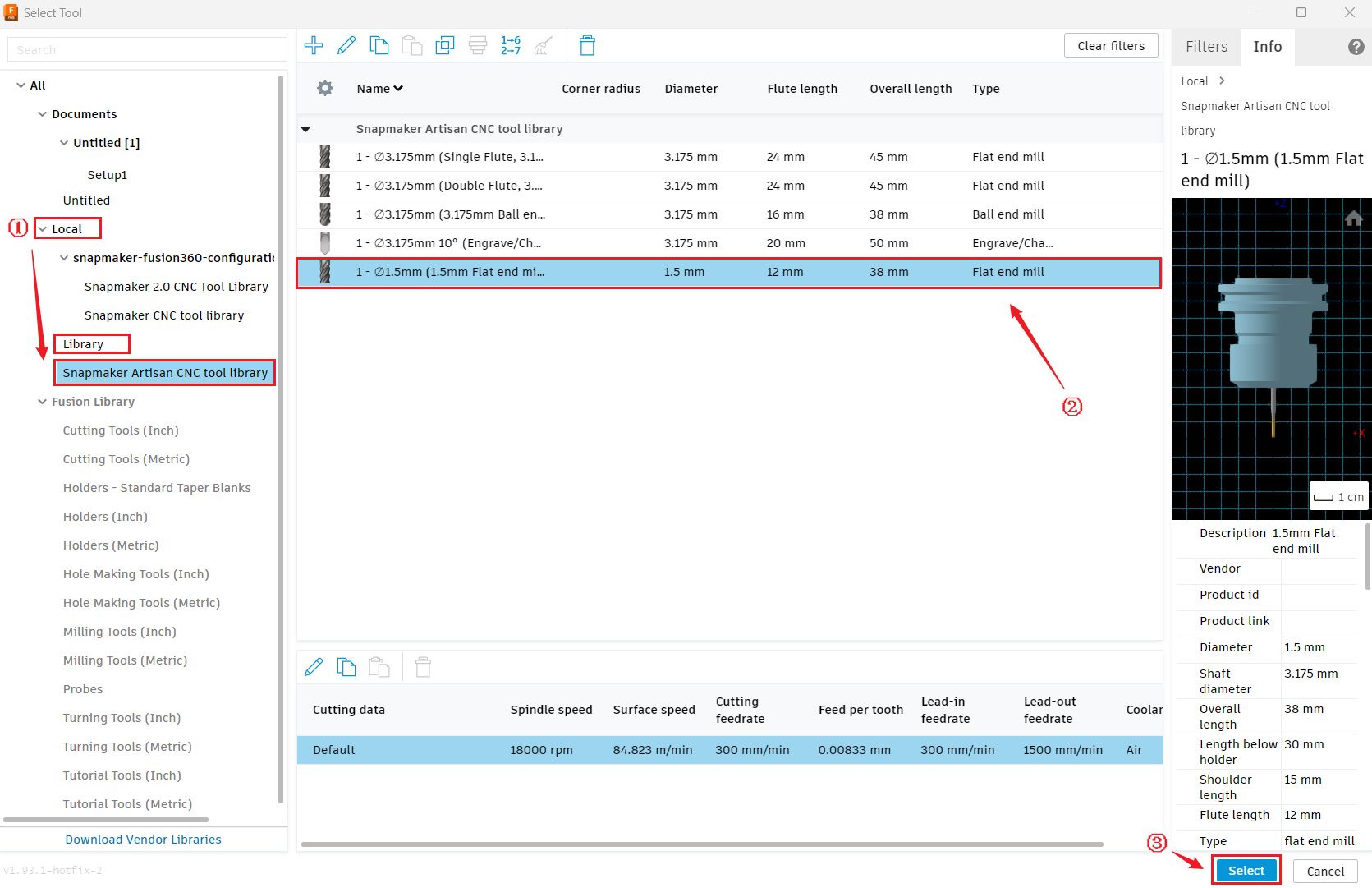
- In the pop up window, click Local > Library > Snampaker Artisan CNC tool library, select 1.5mm flat end mill, then click Select.
- Set Spindle Speed to 18000 rmp.
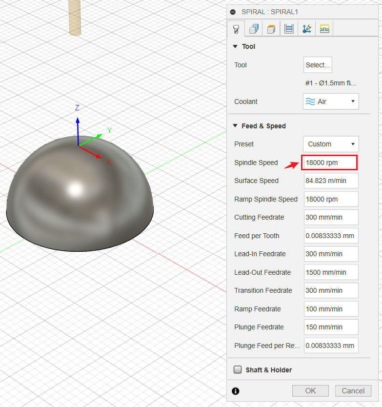
After successfully selecting the tool, do not click OK yet, because there are other parameters to be set in the following steps.
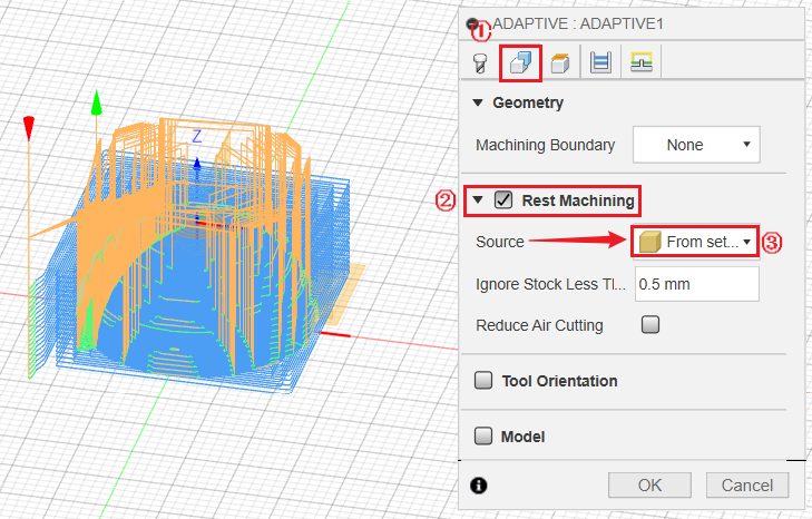
- Switch to Geometry tag, tick Rest Machining, select from setup stock as Source.
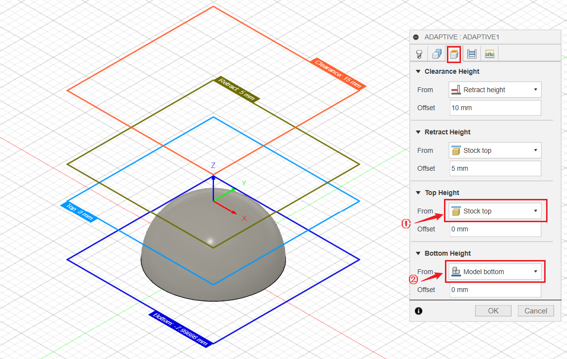
- Switch to Heights tag, set Top Height as Stock top, set Bottom Height as Model bottom.
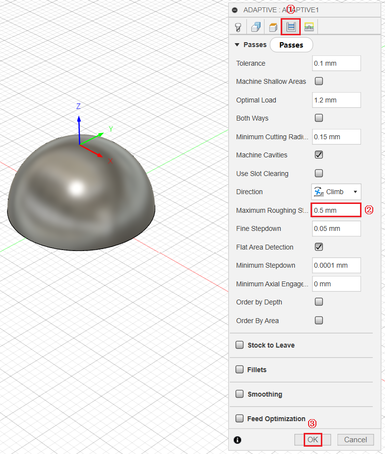
- Switch to Passes tag, set Maximum Roughing Stepdown to 0.5 mm.
¶ Generate and export G-code file
To run multi-process 3-axis CNC work in Fusion 360, you have to seperately generate the G-code file for each process.
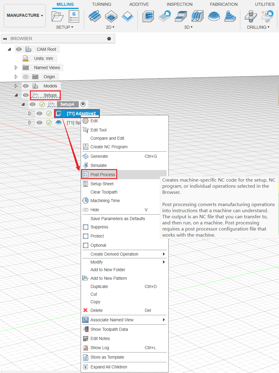
- Click Setups, select the toolpath for roughing processing. Then right click and select Post Process.
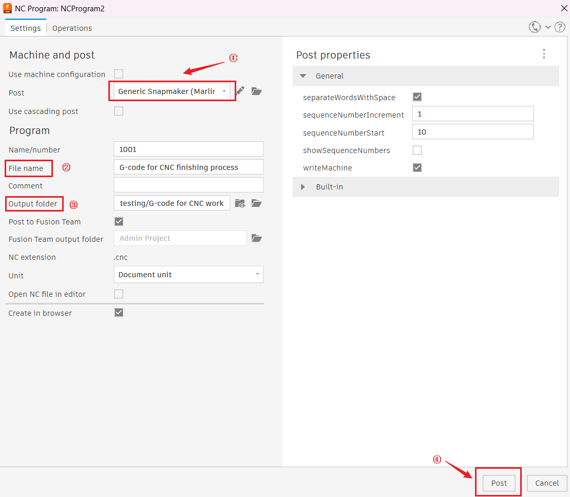
- Select the Generic Snapmaker (Marlin) / snapmaker as Post. Then input your file name, select output folder, and click Post.
If it's your first time using Fusion 360, please refer to Snapmaker post process in Fusion 360 to import Snapmaker post processor Generic Snapmaker (Marlin) / snapmaker.
¶ Finishing process
¶ Create the toolpath
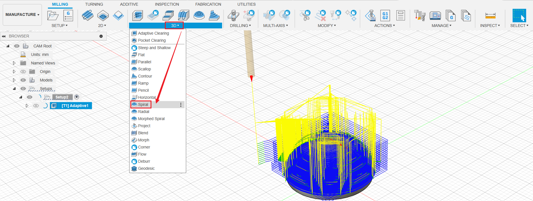
- Click 3D > Spiral.
-
Under Tools tag, click Select.
-
In the pop up window, click Local > Library > Snampaker Artisan CNC tool library, select 3.175mm ball end mill, then click Select.
-
Set Spindle Speed to 18000 rmp.
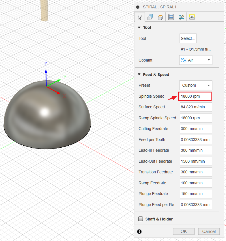
After successfully selecting the tool, do not click OK yet, because there are other parameters to be set in the following steps.
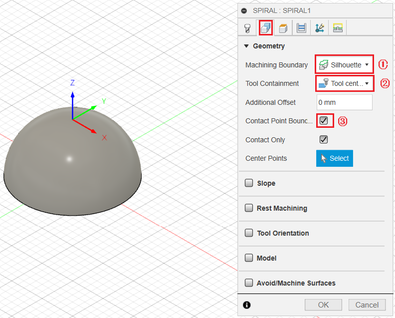
- Switch to Geometry tag, set Machining Boundary as Silhouette, set Tool Containment as Tool center on boundary, and tick Contact Point Boundary.
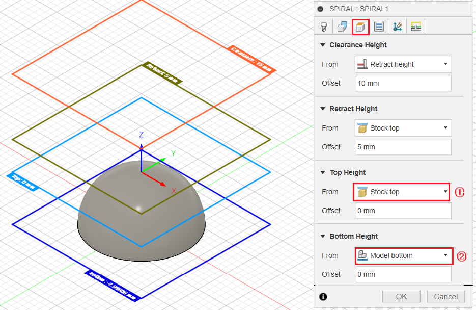
- Switch to Heights tag, set Top Height as Stock top, and set Bottom height as Model bottom.
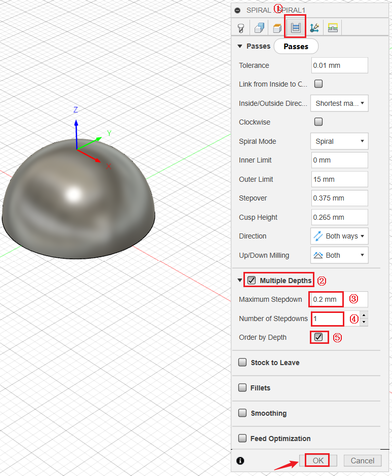
- Switch to Passes tag, tick Multiple Depth, set Maximum Stepdown to 0.2mm, set Number of Stepdowns to 1, and tick Order by Depth. Click OK when finished.
¶ Generate and export G-code file
- Click Setups, select the toolpath for roughing processing. Then right click and select Post Process.
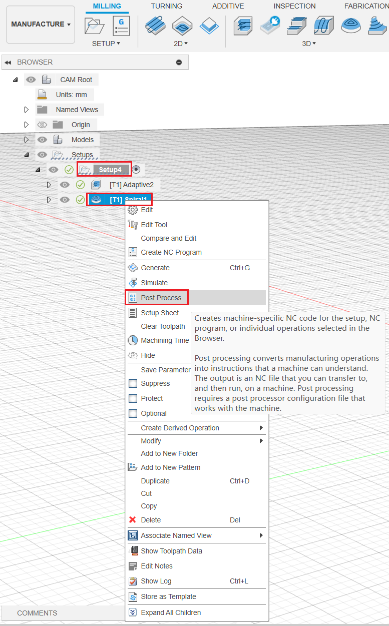
- Select the Generic Snapmaker (Marlin) / snapmaker as Post. Then input your file name, select output folder, and click Post.
¶ 2D contour process
¶ Create the toolpath
- Click 2D > 2D Contour.

-
Under Tools tag, click Select.
-
In the pop up window, click Local > Library > Snampaker Artisan CNC tool library, select 1.5mm flat end mill, then click Select.
After successfully selecting the tool, do not click OK yet, because there are other parameters to be set in the following steps.
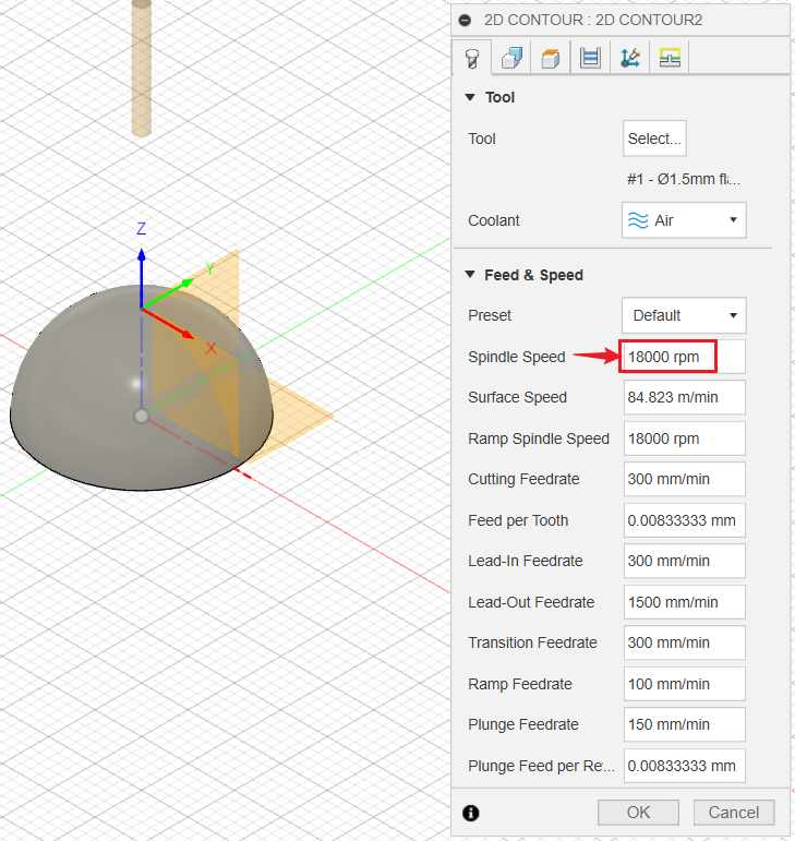
- Set Spindle Speed to 18000 rmp.
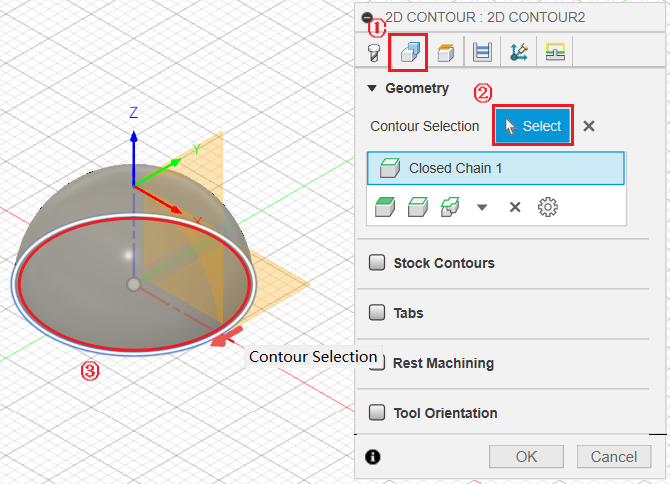
- Switch to Geometry tag, click Select, then select the bottom circle as the contour face.
- Tick Tabs. Then set two or more tabs based on your own needs.
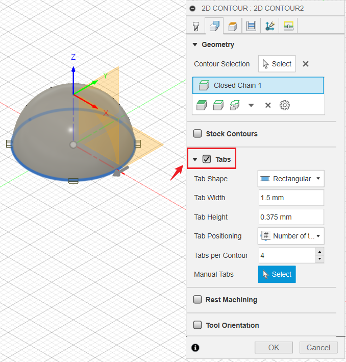
Adding a couple of tabs around the solid can help hold it down on the stock during processing.
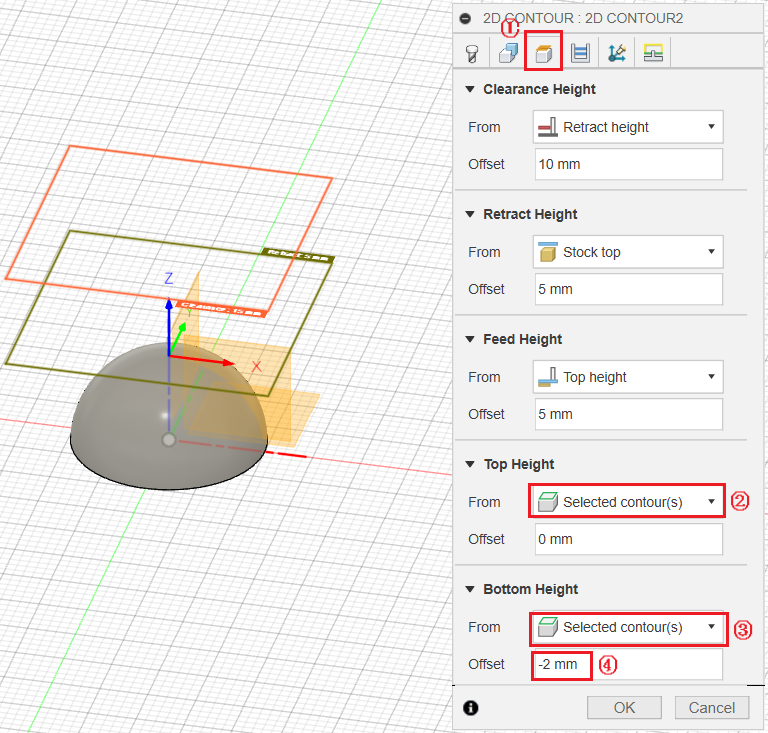
- Go to Heights tag. For Top Heights, select Selected contour(s), set Offset as 0mm. For Bottom Height, select Selected contour(s), set Offset as -2mm.
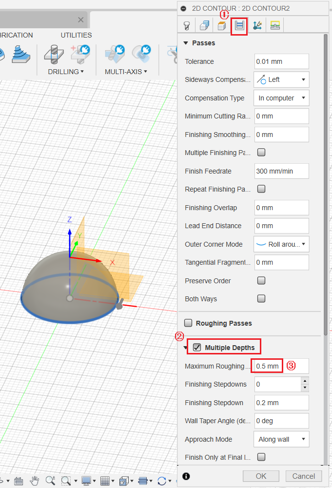
- Go to Passes tag, tick Multiple Depth, set Maximum Roughing Stepdown to 0.5mm. Click OK when finished.
¶ Generate and export G-code file
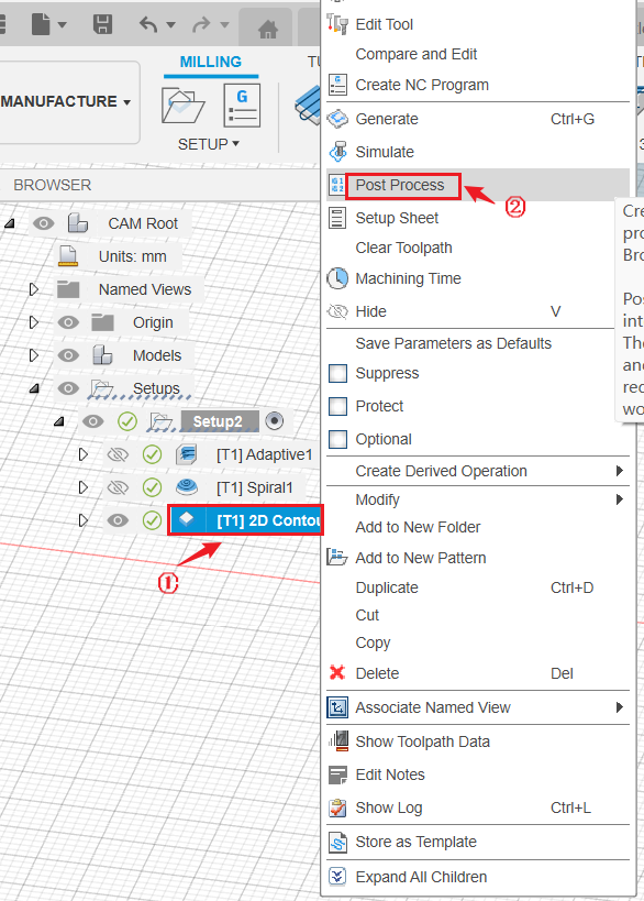
- Click Setups, select the toolpath for the 2D contour. Then right click and select Post Process.
- Select the Generic Snapmaker (Marlin) / snapmaker as Post. Then input your file name, select output folder, and click Post.
¶ 3.4 Transfer G-code files to the machine
- Copy the exported .cnc G-code file to USB flash drive.
- Insert USB flash drive into the Integrated Controller.
- On Touchscreen, tap Start > Files > Local, you will find your .cnc G-code file.
- Copy the exported .cnc G-code file to USB flash drive.
- Insert USB flash drive into the Controller.
- On Touchscreen, tap Files > USB, you will find your .cnc G-code file.
¶ 3.5 Operate on the machine and Touchscreen
¶ Roughing process
¶ Install the CNC bit
Please read the instructions below to install 1.5mm flat end mill onto your 200W CNC Module.
¶ Set the work origin
Make sure that you have clamped the material correctly before setting the work origin. Again, make sure that the height of the material is no smaller than the model radius (which is 10mm in this case), otherwise your CNC Carving and Cutting platform will get cut and damaged.
Open the G-code file for the roughing process, tap Next. Then read the instructions below to set the work origin on Touchscreen.
Make sure that you have clamped the material correctly before setting the work origin. Again, make sure that the height of the material is no smaller than the model radius (which is 10mm in this case), otherwise your CNC Carving and Cutting platform will get cut and damaged.
On Touchscreen, open the G-code file, and refer to section 5.6 Set the Work Origin and Start Carving to set the work origin.
¶ Start roughing process
Tap Start Job on Touchscreen to start the CNC roughing process.
Ensure that you place the Integrated Controller within easy reach. In case of an emergency, press the emergency stop button on top of the Integrated Controller to stop the job immediately. After you have handled the emergency, rotate the emergency stop button clockwise to release it.
It is not recommended to turn on the exhaust fan of the Enclosure during a CNC process, or the dust and wood chips generated will attach to the inner surfaces of the Enclosure and the exhaust fan.
The shape of half sphere will appear when the roughing process finishes.
¶ When finished, measure the distance between the bottom of the Module and the bit tip
Before removing the 1.5mm flat end mill bit from the CNC Module, measure the distance (h) between the bottom of the CNC module and the tip of the CNC bit.

Please do not move the X, Y or Z axis during the measurement.
¶ Finishing process
¶ Change the CNC bit
- Please read the instructions below to change the CNC bit into 3.175 ball end mill, which will be used for finishing process.
- After changing the bit, measure the distance between the bottom of the CNC module and the tip of the CNC bit (h1) again. If h1 = h, you can start the job directly; if h1 ≠ h, please refer to the step below to adjust the height of the Z-axis.
¶ (Optional) Adjust the Z-axis height
The length of bits might be different. Therefore, after changing bits, the distance between the bottom of the CNC module and the tip of the CNC bit might also change. In such case, please reset the origin of Z-axis height.
¶ Start finishing process
Tap Start Job on Touchscreen to start CNC finishing machining.
Ensure that you place the Integrated Controller within easy reach. In case of an emergency, press the emergency stop button on top of the Integrated Controller to stop the job immediately. After you have handled the emergency, rotate the emergency stop button clockwise to release it.
It is not recommended to turn on the exhaust fan of the Enclosure during a CNC process, or the dust and wood chips generated will attach to the inner surfaces of the Enclosure and the exhaust fan.
The surface of the half sphere would become smooth when the finishing process ends.
¶ When finished, measure the distance between the bottom of the Module and the bit tip
Before removing the 3.175 ball end mill bit from the CNC Module, measure the distance (h) between the bottom of the CNC module and the tip of the CNC bit.

Please do not move the X, Y or Z axis during the measurement.
¶ 2D contour
¶ Change the CNC bit
- Please read the instructions below to change the CNC bit into 1.5mm flat end mill, which will be used for 2D contour process.
- After changing the bit, measure the distance between the bottom of the CNC module and the tip of the CNC bit (h1) again. If h1 = h, you can start the job directly; if h1 ≠ h, please refer to the step below to adjust the height of the Z-axis.
¶ (Optional) Adjust the Z-axis height
The length of bits might be different. Therefore, after changing bits, the distance between the bottom of the CNC module and the tip of the CNC bit might also change. In such case, please reset the origin of Z-axis height.
¶ Start 2D contour process
Tap Start Job on Touchscreen to start the 2D contour process.
Ensure that you place the Integrated Controller within easy reach. In case of an emergency, press the emergency stop button on top of the Integrated Controller to stop the job immediately. After you have handled the emergency, rotate the emergency stop button clockwise to release it.
It is not recommended to turn on the exhaust fan of the Enclosure during a CNC process, or the dust and wood chips generated will attach to the inner surfaces of the Enclosure and the exhaust fan.
The half sphere model will be separated from the material when the 2D contour process finishes.
¶ 3.6 Clean the finished work and the machine
Gently remove the tabs around it, then your half sphere is done. Happy making!
