¶ Overview
¶ Location
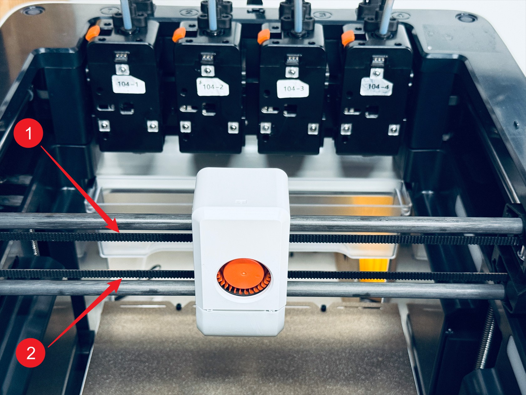
The XY axis timing belt system consists of two timing belts, one upper and one lower.
¶ Practicality
Difficulty:★★★★★ (difficult)
Estimated Time:120mins
¶ Where to Buy
¶ Tools and Parts Required
(1) H1.5 Hex Key
(2) H2.0 Hex Key
(3) Scissors / Flathead screwdriver
(4) Tweezers
(5) Needle-nose Pliers
(6) New Timing Belt × 2: 2GT-6RF, Single length ≥ 175 cm
(7) Glue
(8) Zip tie
¶ Procedure
¶ Step 1. Pre-install timing belts
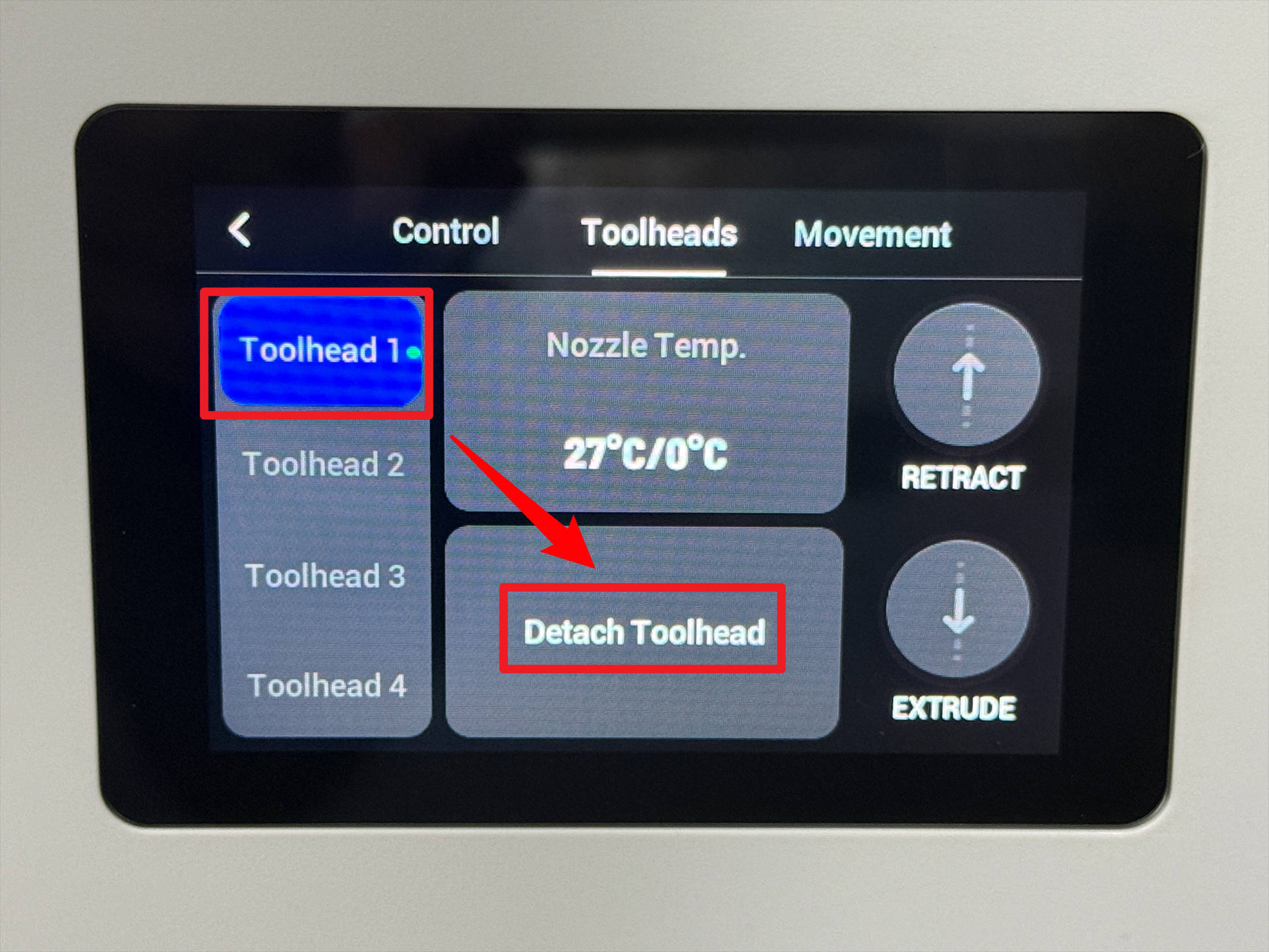
(1) Select the toolhead currently attached to the swapper then tap "Detach Toolhead".
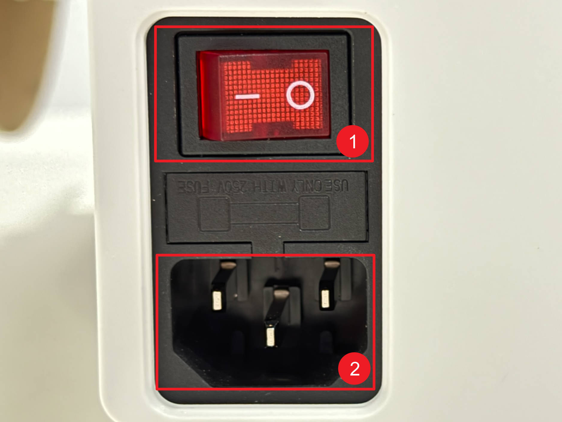
(2) power off U1 and unplug it.
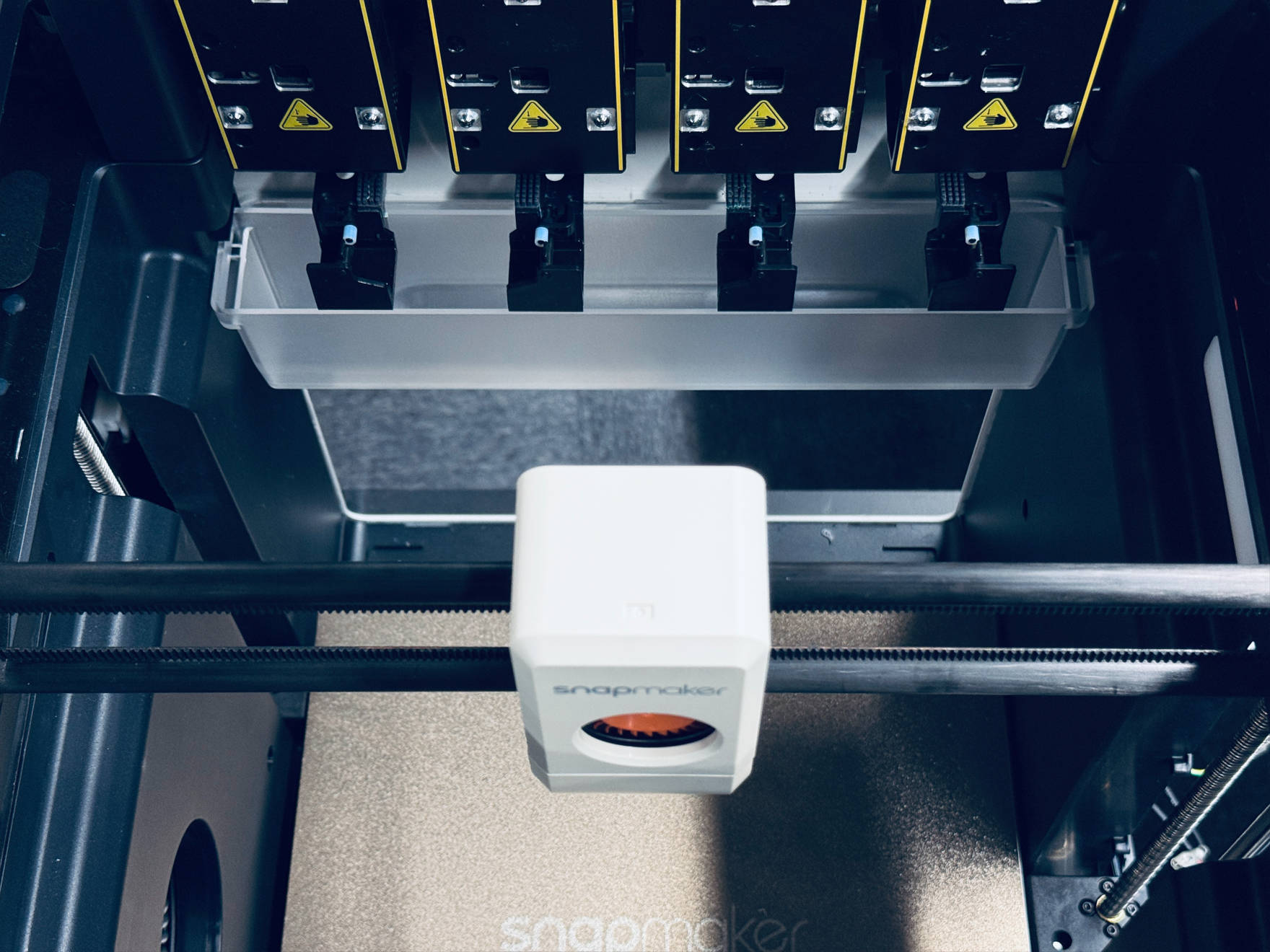
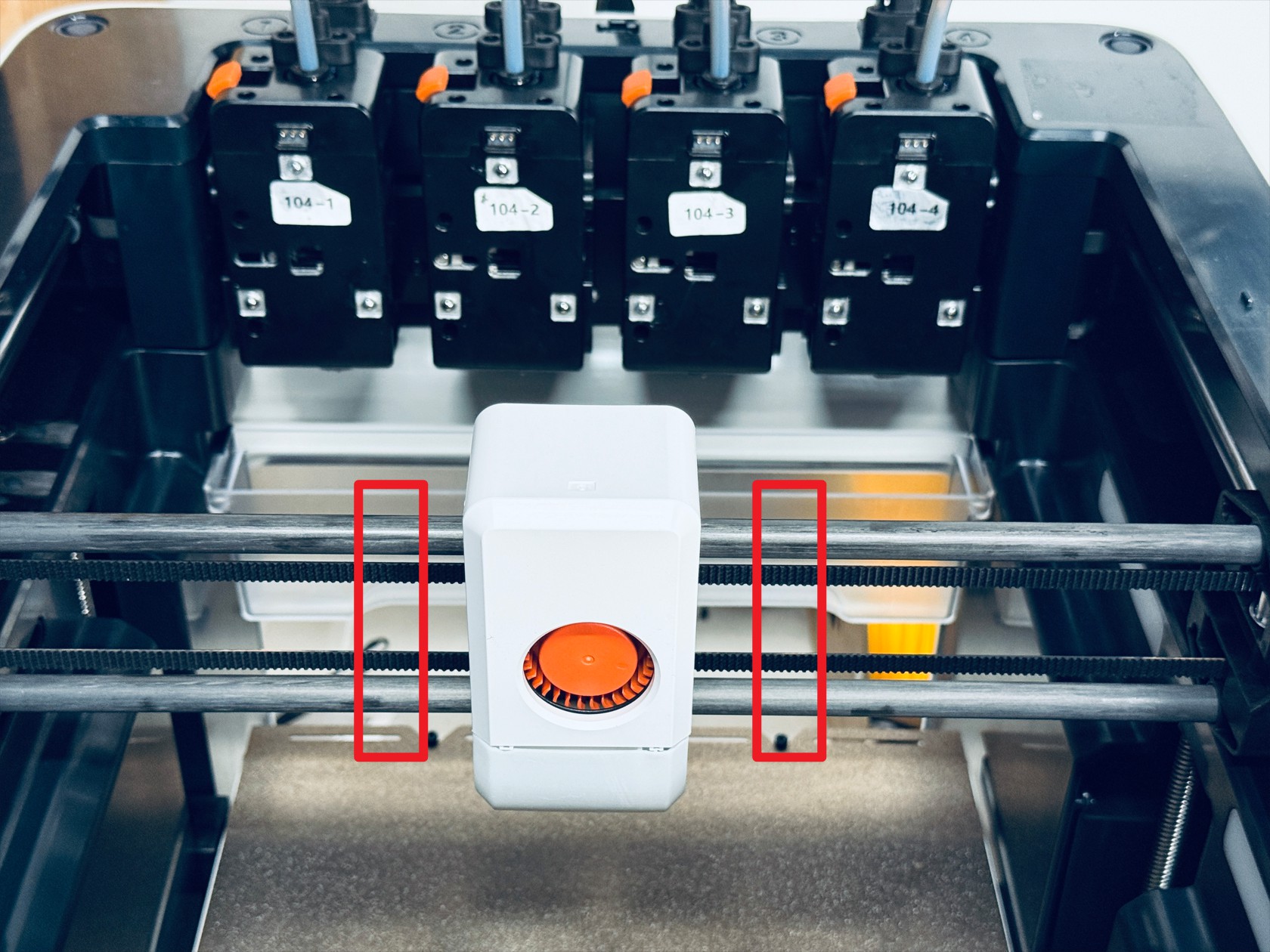
(3) Manually move the toolhead swapper to the center of the XY plane
(4) Use scissors to cut both timing belts along the dashed line.
Do not pull out the timing belts after cutting them !
(5) Glue new timing belt to one end of the old one (make sure the teeth face the same direction). After the glue dries, pull the other end of the old belt until the new belt comes through. Finally, cut off the joint between the old and new belts with scissors.
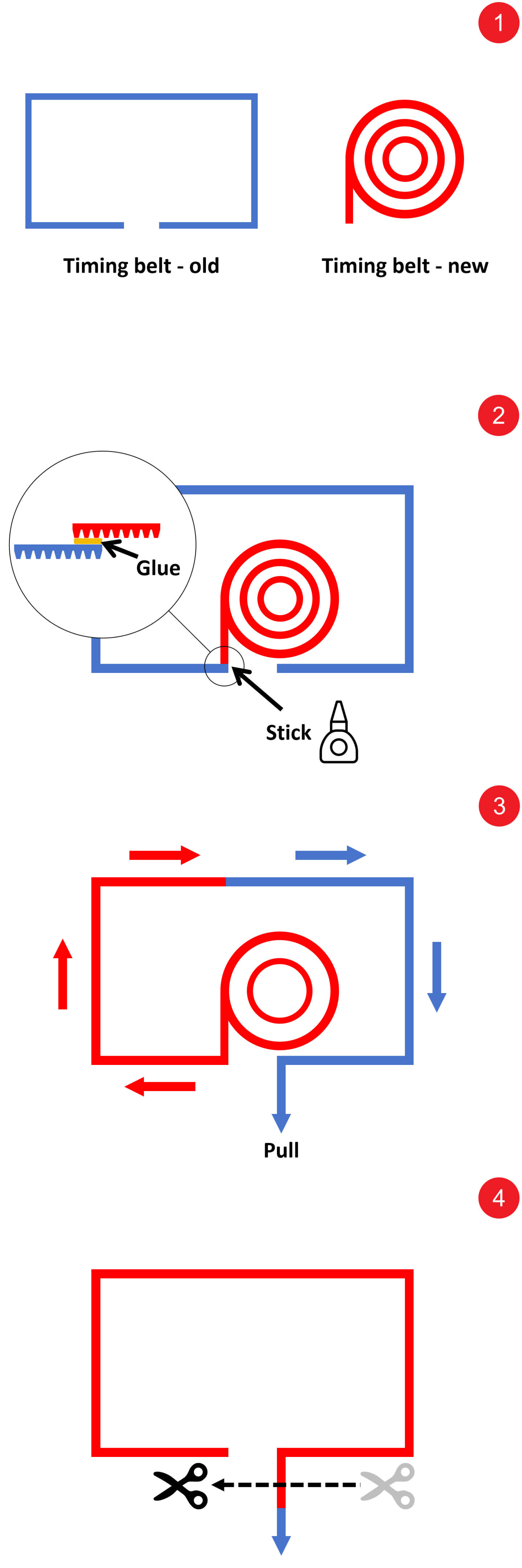
(6) Pre-install the other timing belt using the same method.
¶ Step 2. Remove the toolhead swapper
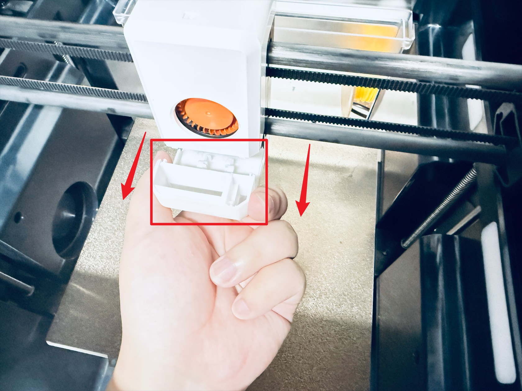
(1) Use an H2.0 hex key to unscrew 2 screws and remove the part cooling fan air duct and part cooling fan shroud
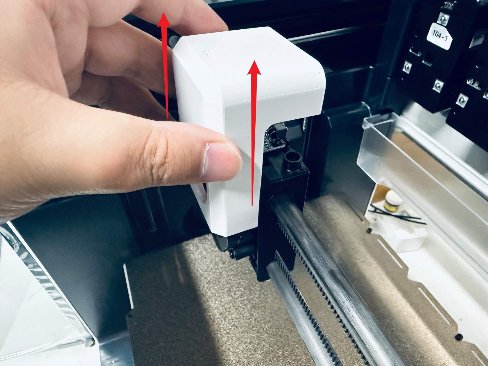
(2) Disconnect the part cooling fan cable then use an H2.0 hex key to unscrew 2 screws and remove the part cooling fan

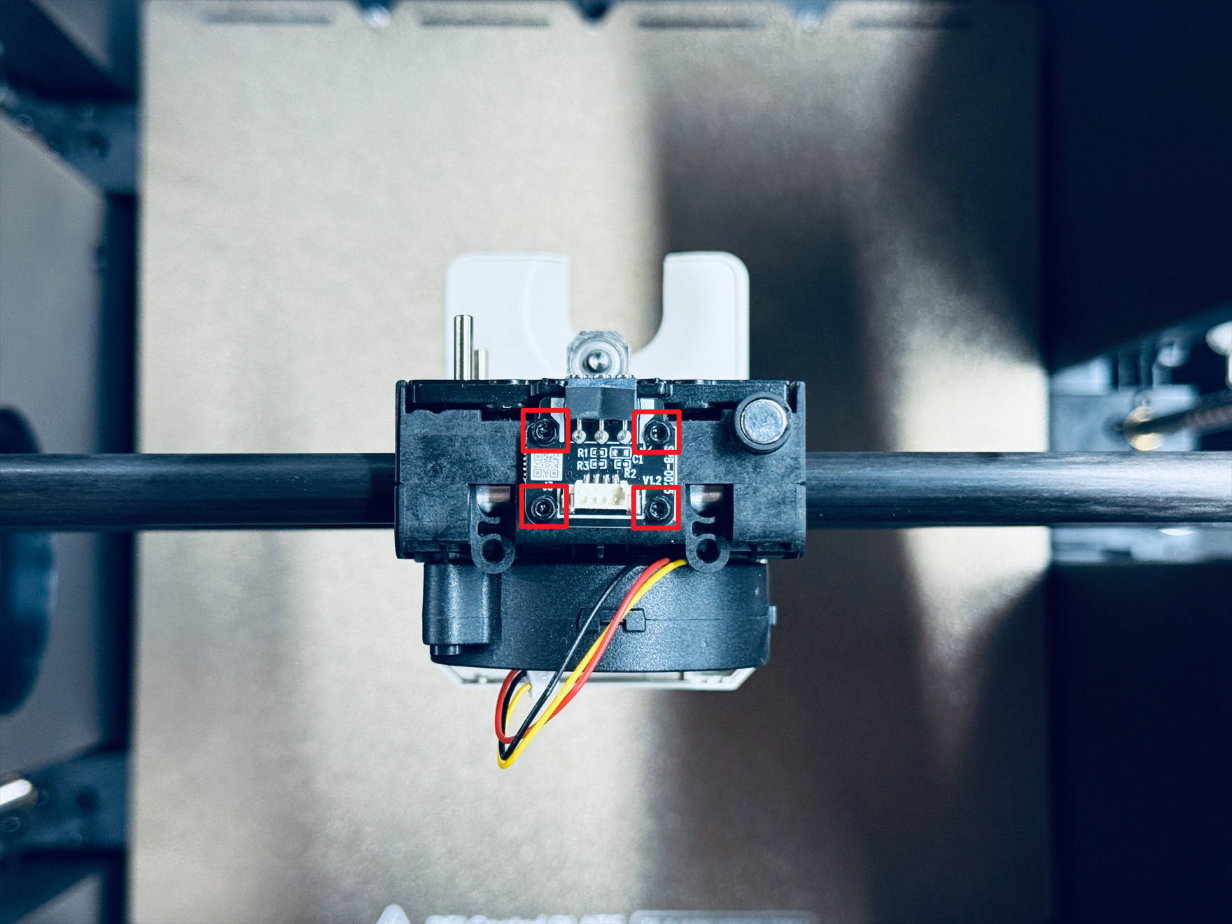
(3) Use an H1.5 hex key to unscrew 4 screws and remove the part cooling fan adapter board
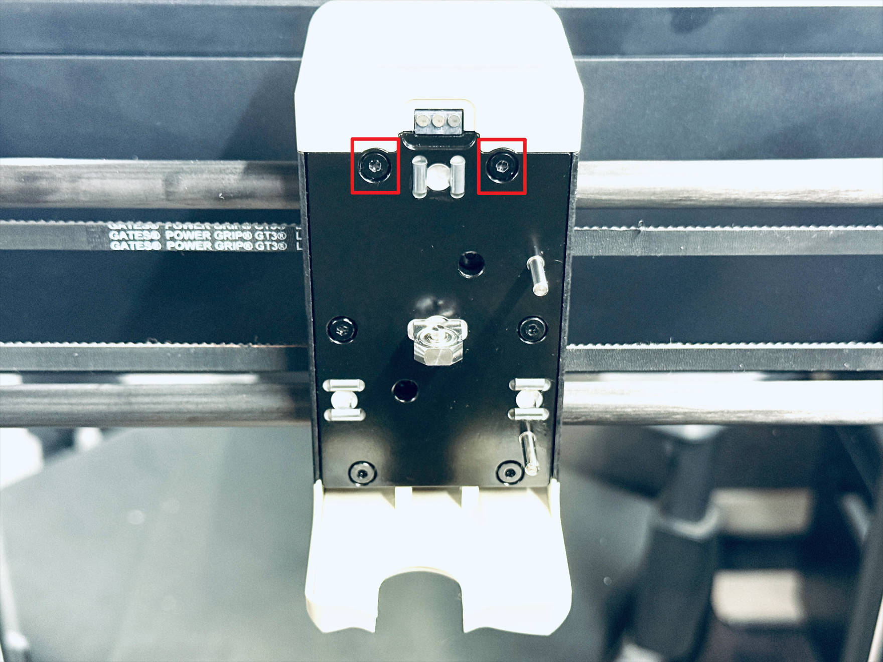
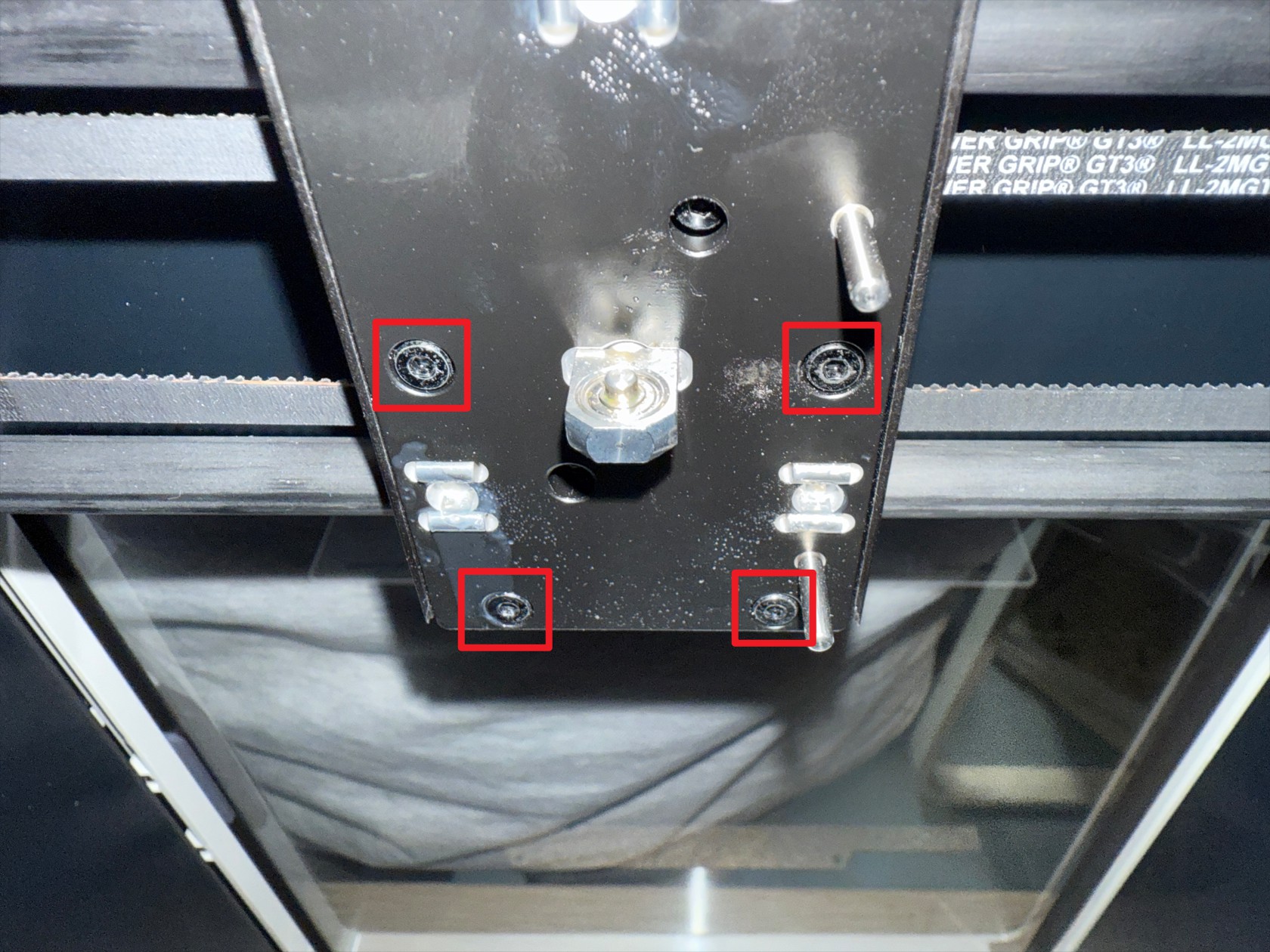
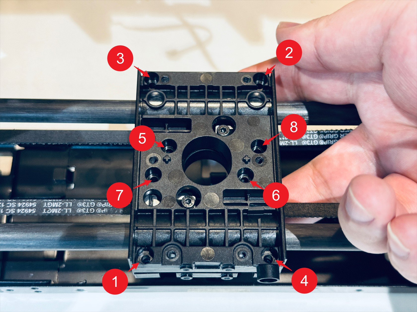
(4) Use an H2.0 hex key to unscrew 4 screws and remove the toolhead swapper base
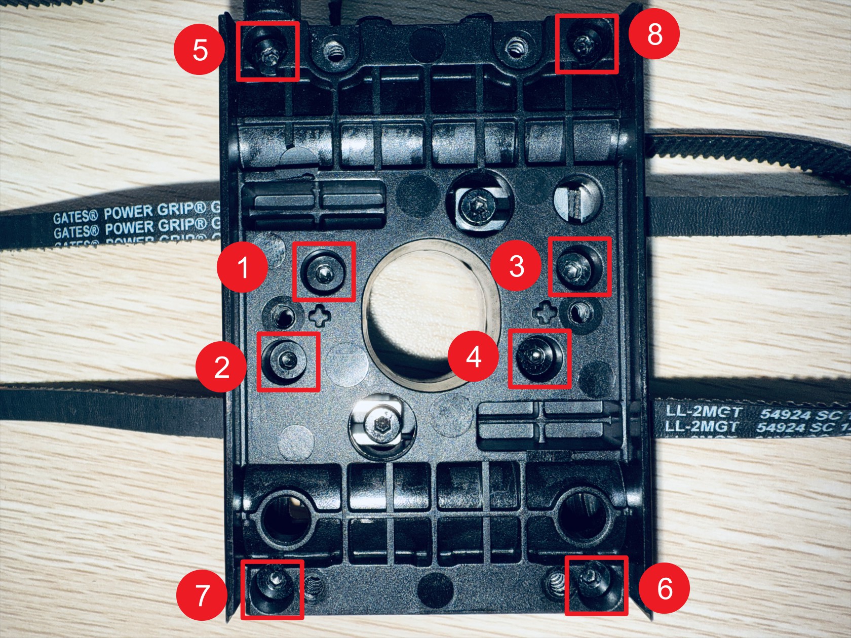
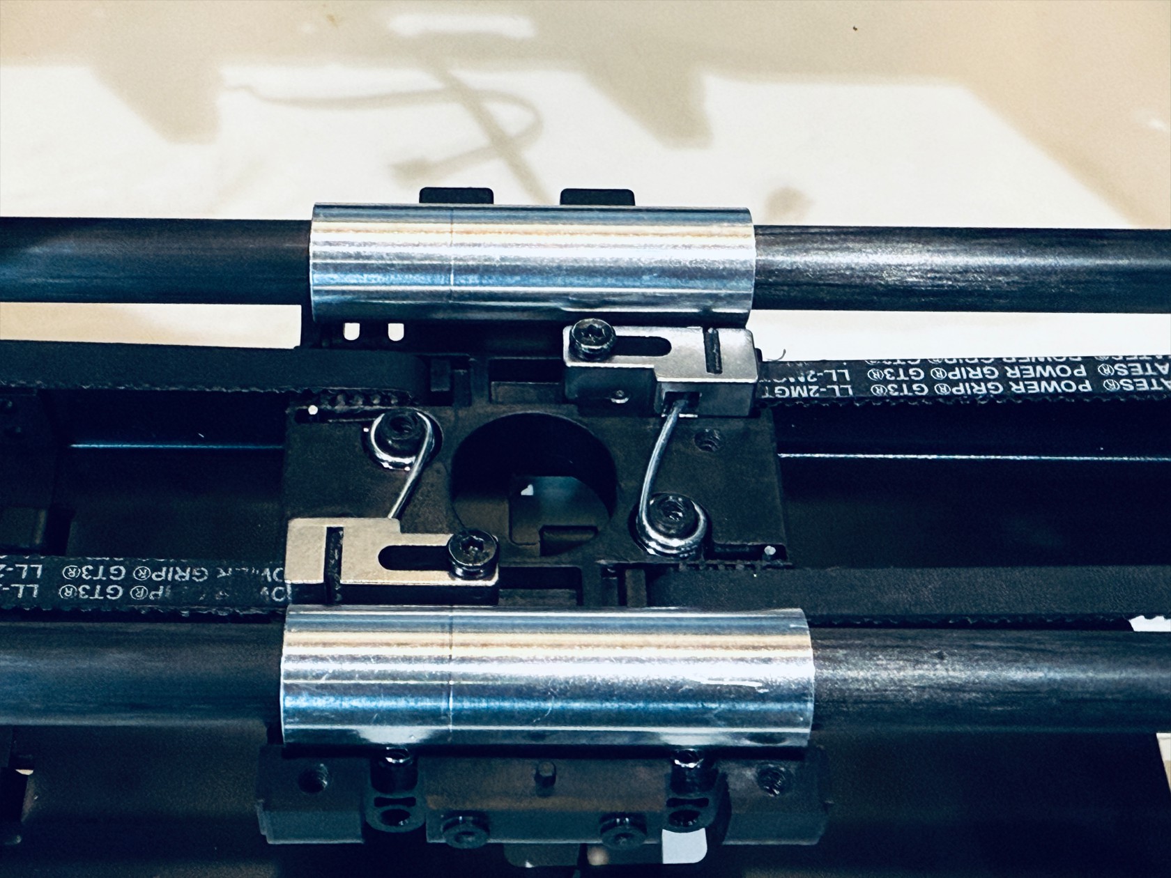
(5) Use an H2.0 hex key to sequentially unscrew 8 screws and separate X-axis slider-1 and X-axis slider-2, note that X-axis slider-2 has 4 anti-backlash springs, after disassembling the X-axis sliders, place them safely to avoid loss
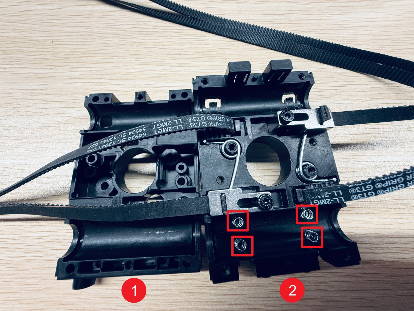
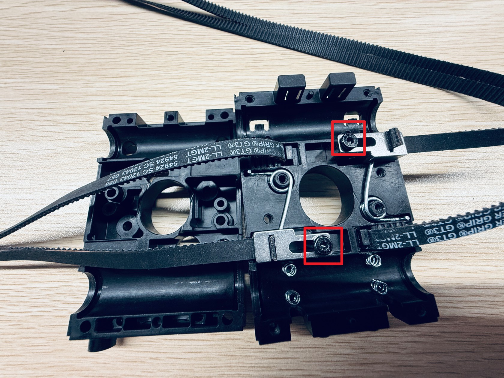
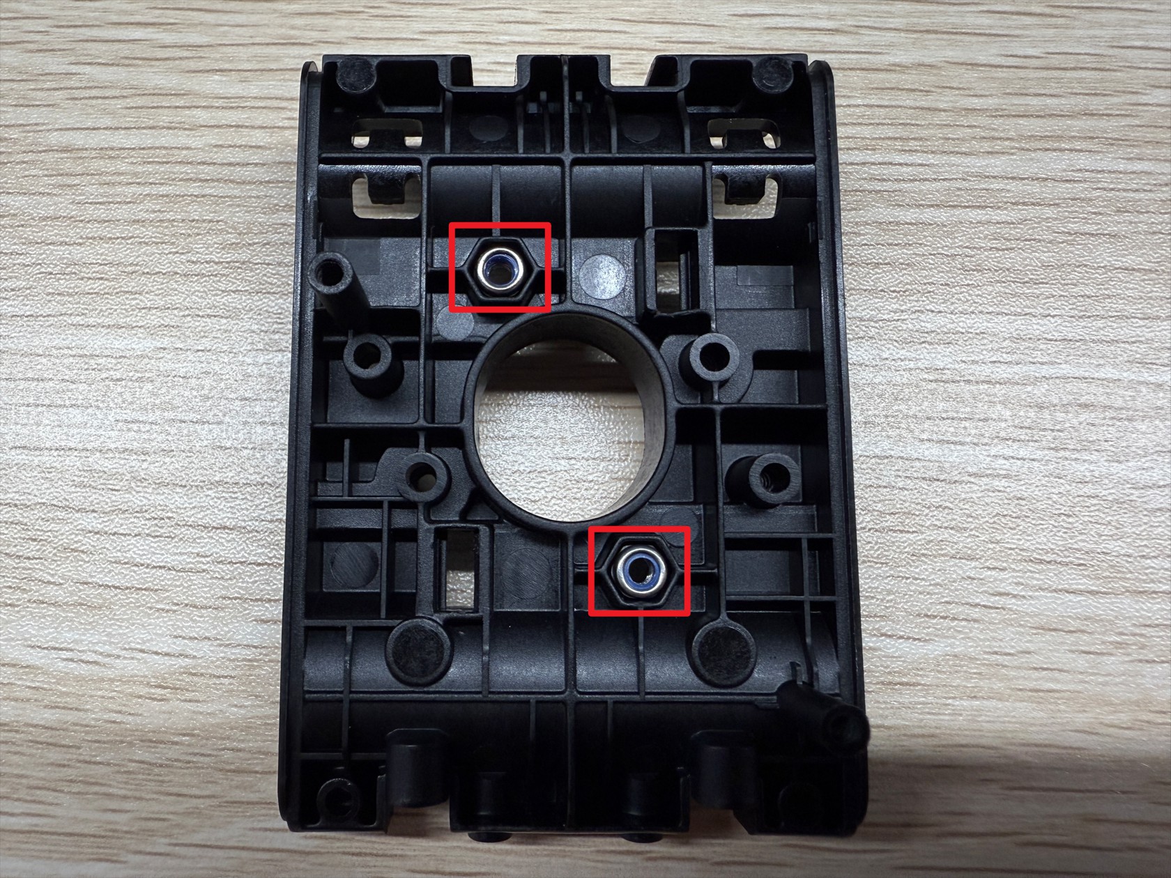
(6) Use an H2.0 hex key to unscrew 2 screws securing the end tensioning movable block, note these 2 screws have lock nuts on the back of the slider, remove and store them safely
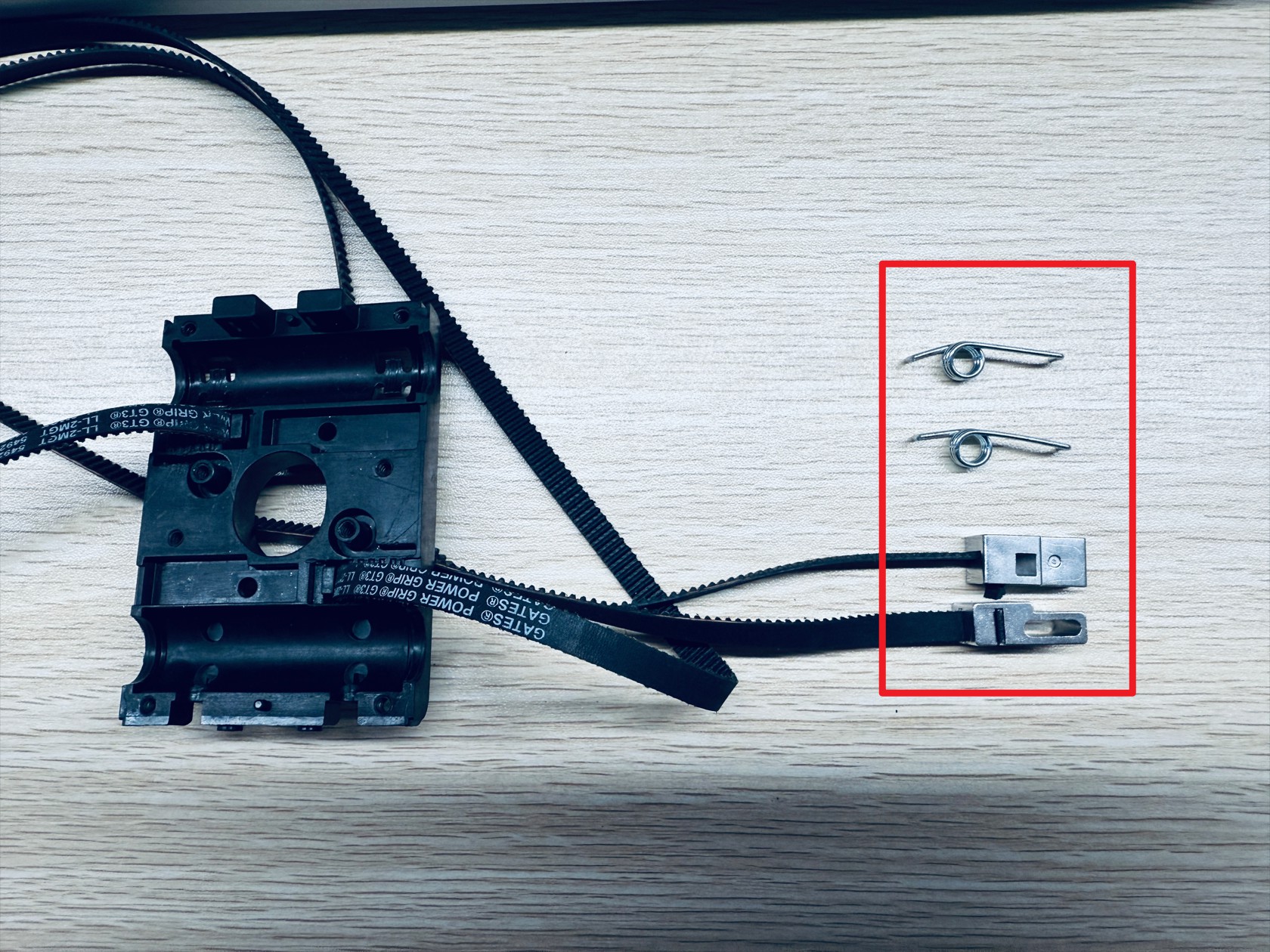
(7) Slowly remove the end tensioning movable block and torsion springs, 2 each.
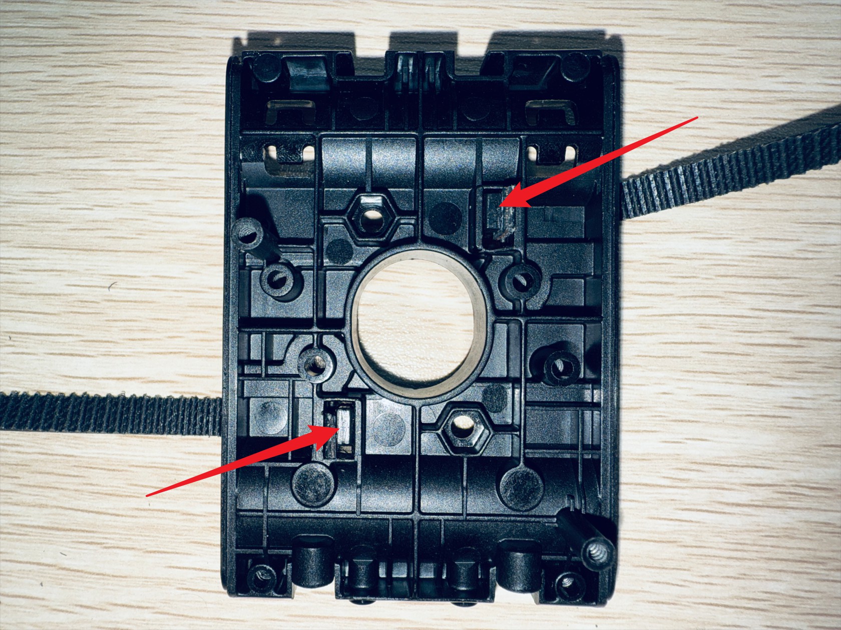
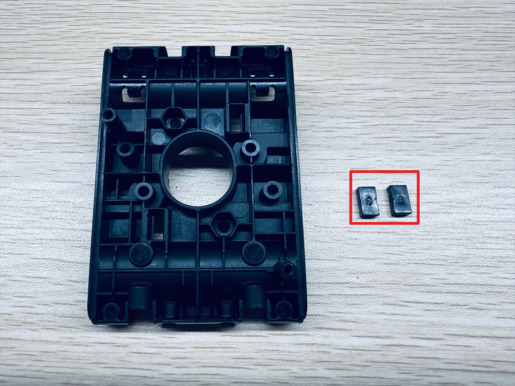
(8) On the outer surface of X-axis slider-2, use an H2.0 hex key to push out the timing belt fixing block and remove the end of the timing belts fixed here
¶ Step 3. Restore the toolhead swapper
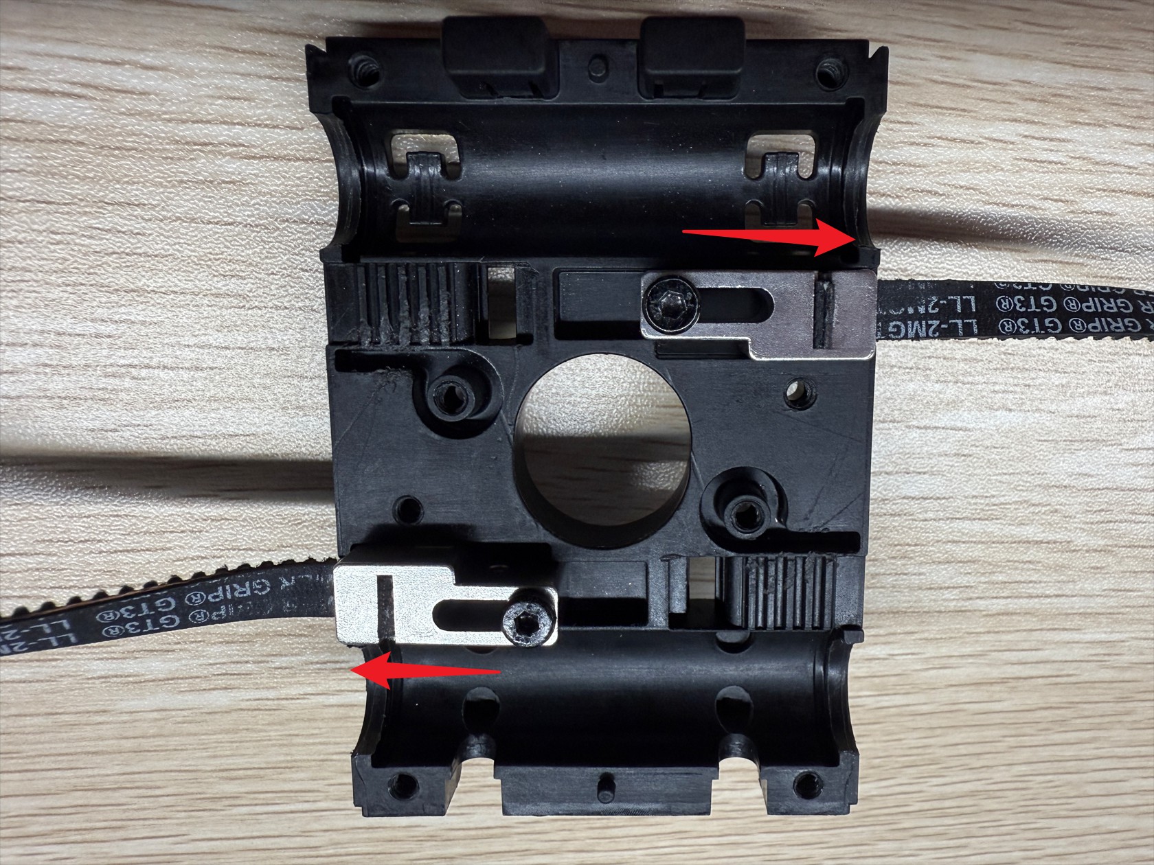
(1) Press the upper timing belt left side and lower timing belt right side into the new end tensioning movable block. Ensure the timing belt teeth align with the end tensioning movable block teeth, and the timing belt sides and front do not protrude from the end tensioning movable block surface
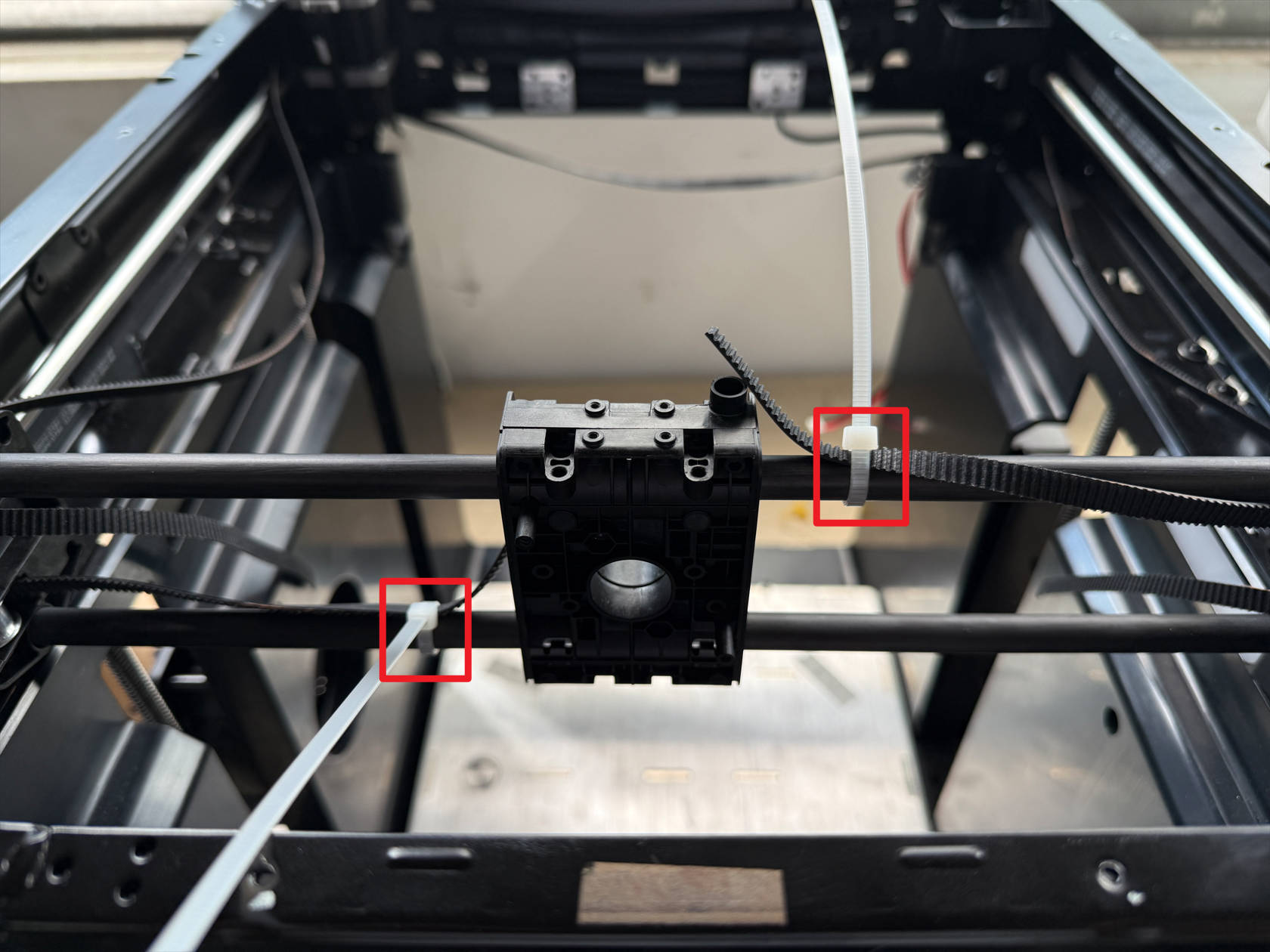
(2) Fix the upper timing belt right side and lower timing belt left side on the carbon rod using zip ties
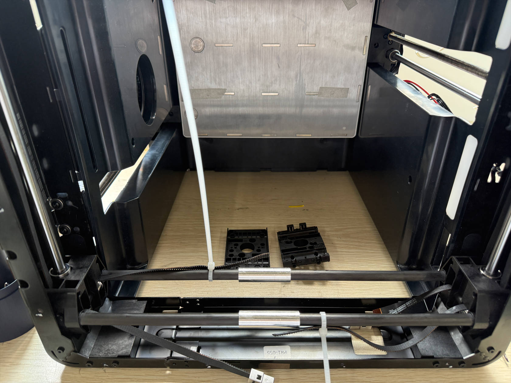
(3) Place the machine front side down
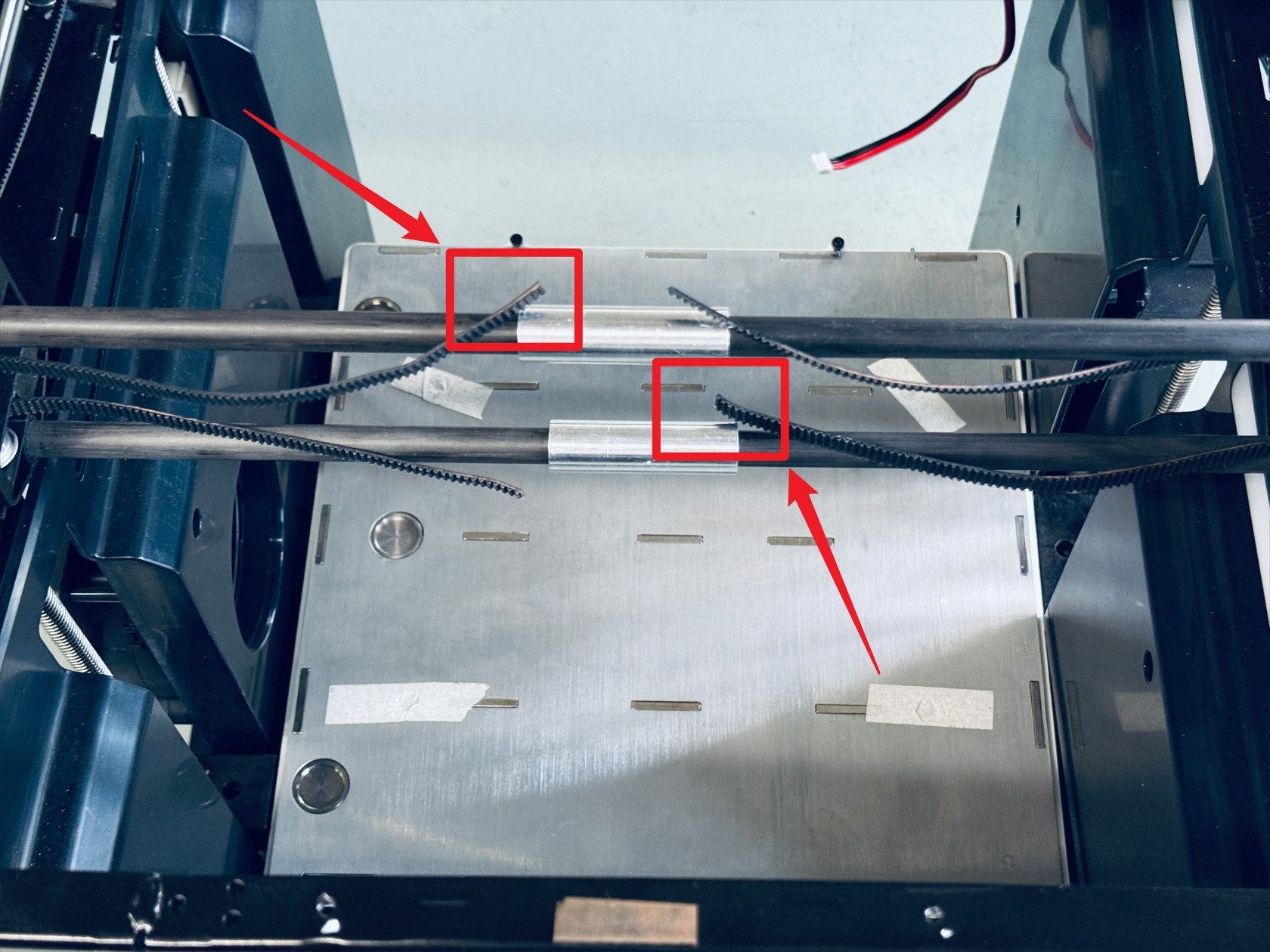
(4) Install the two end tensioning movable blocks with timing belts to the left and right limits of X-axis slider-2 as shown, note the orientation of the movable blocks, use an H2.0 hex key to tighten 2 screws and the lock nuts on the back
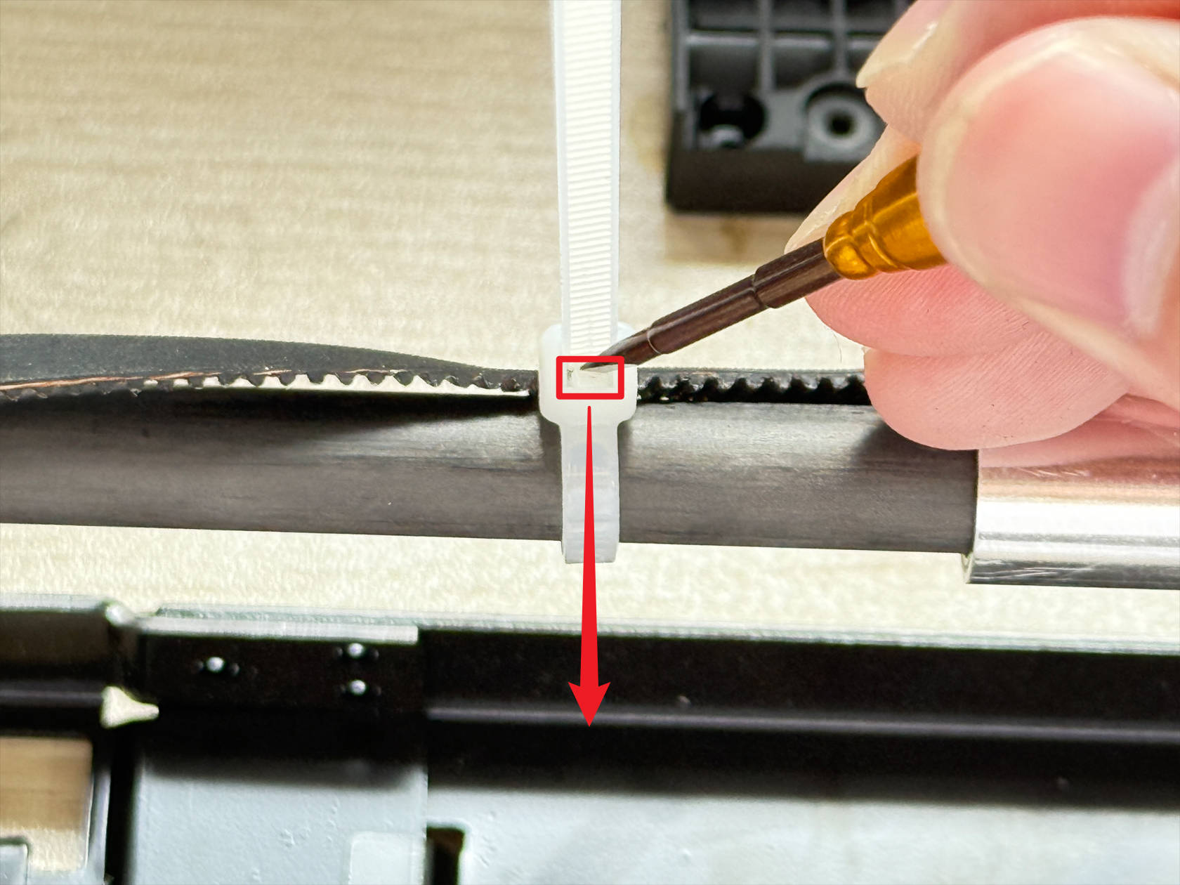
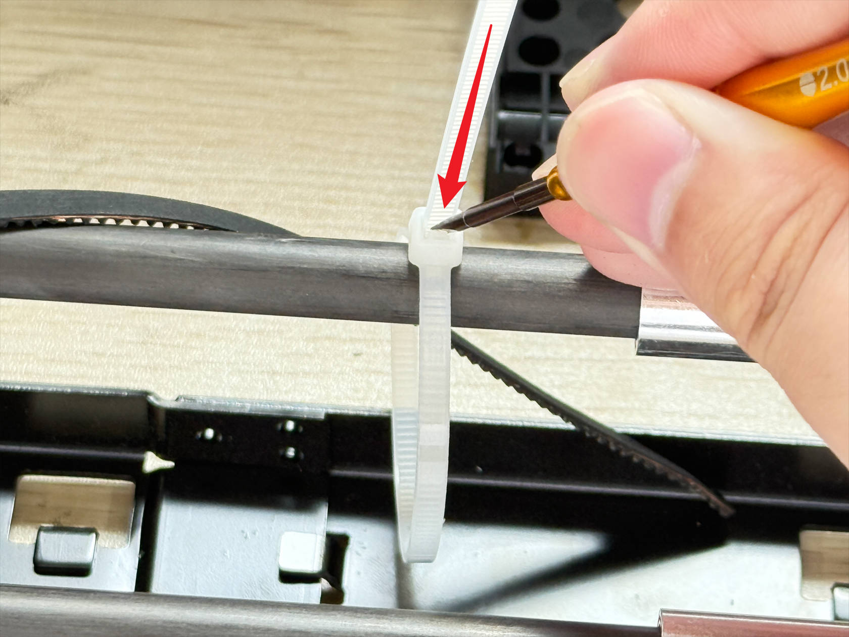
(5) Loosen one of the cable-tied timing belts, use tweezers or a flathead screwdriver to lift the cable tie latch and feed the tied belt back to release
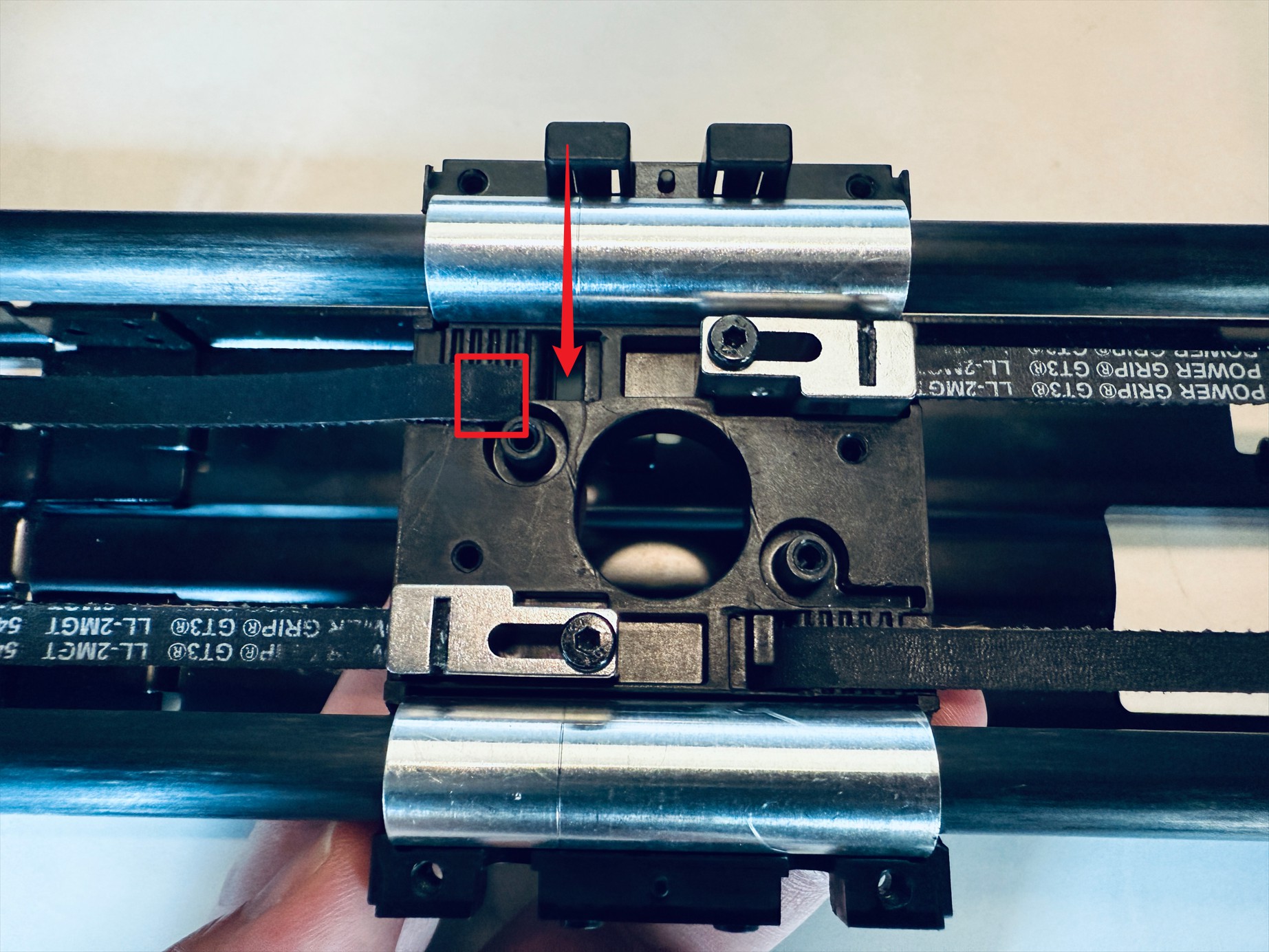
(6) Pass one end of the released timing belt through the illustrated position, keep X-axis slider-2 stationary, straighten and tension the timing belt
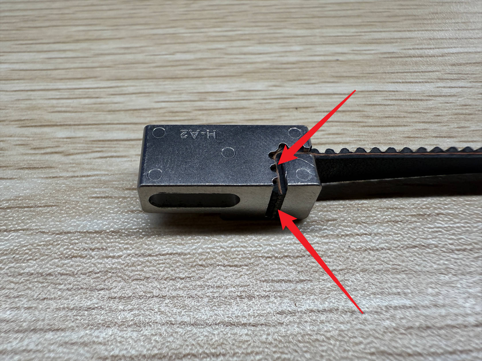
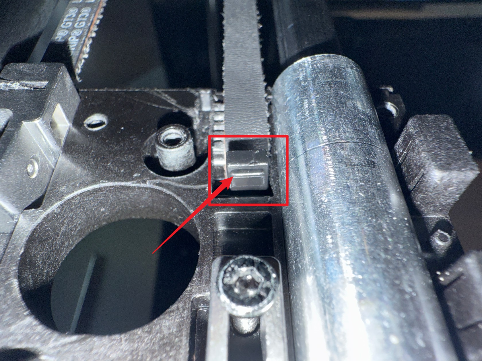
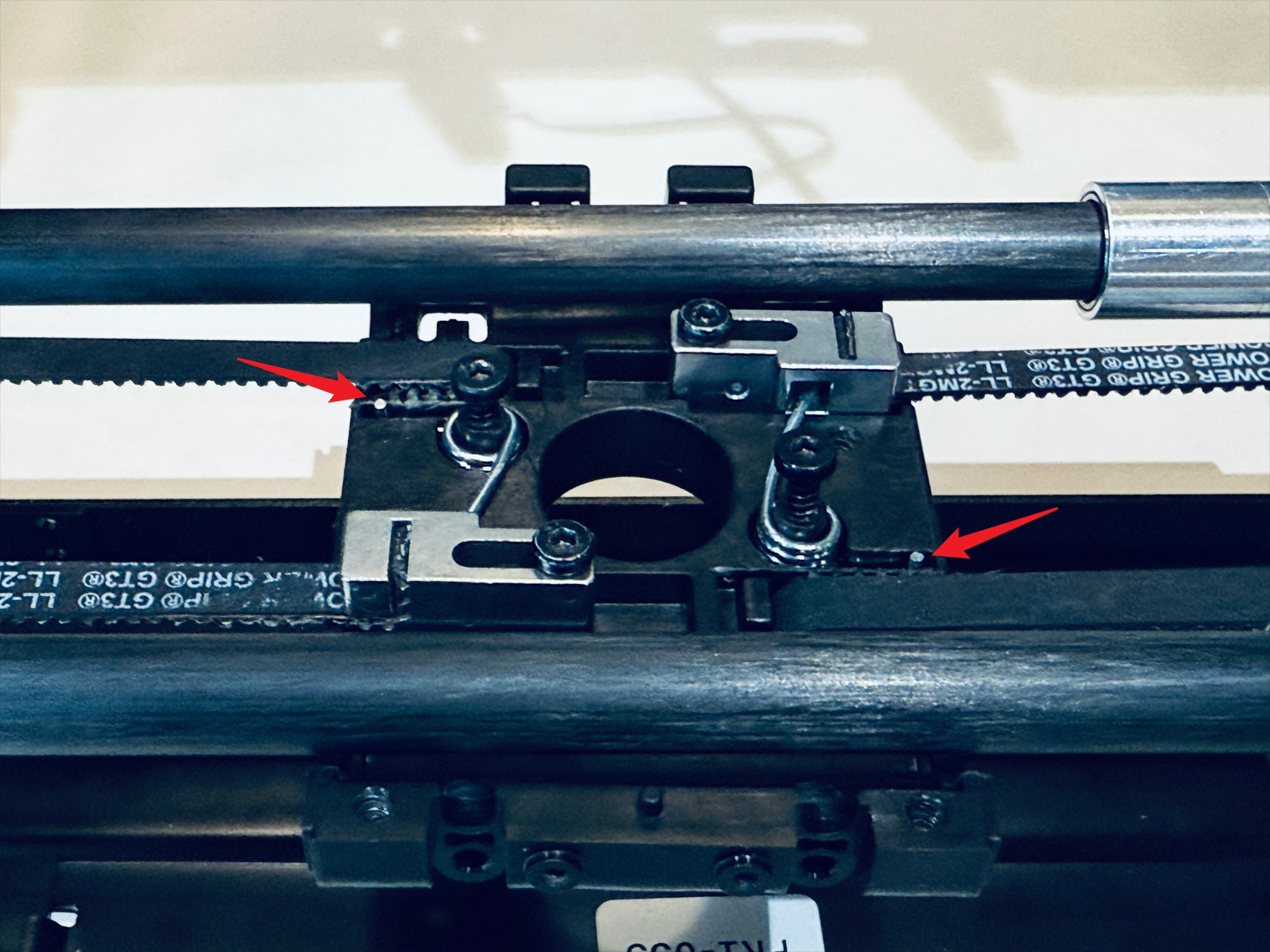
(7) Pre-install the timing belt fixing block, with the grooved end facing up, ensure the back of the groove surface is flush with the timing belt, then use an H2.0 hex key to press the fixing block down until its top is flush with the inner surface of X-axis slider-2

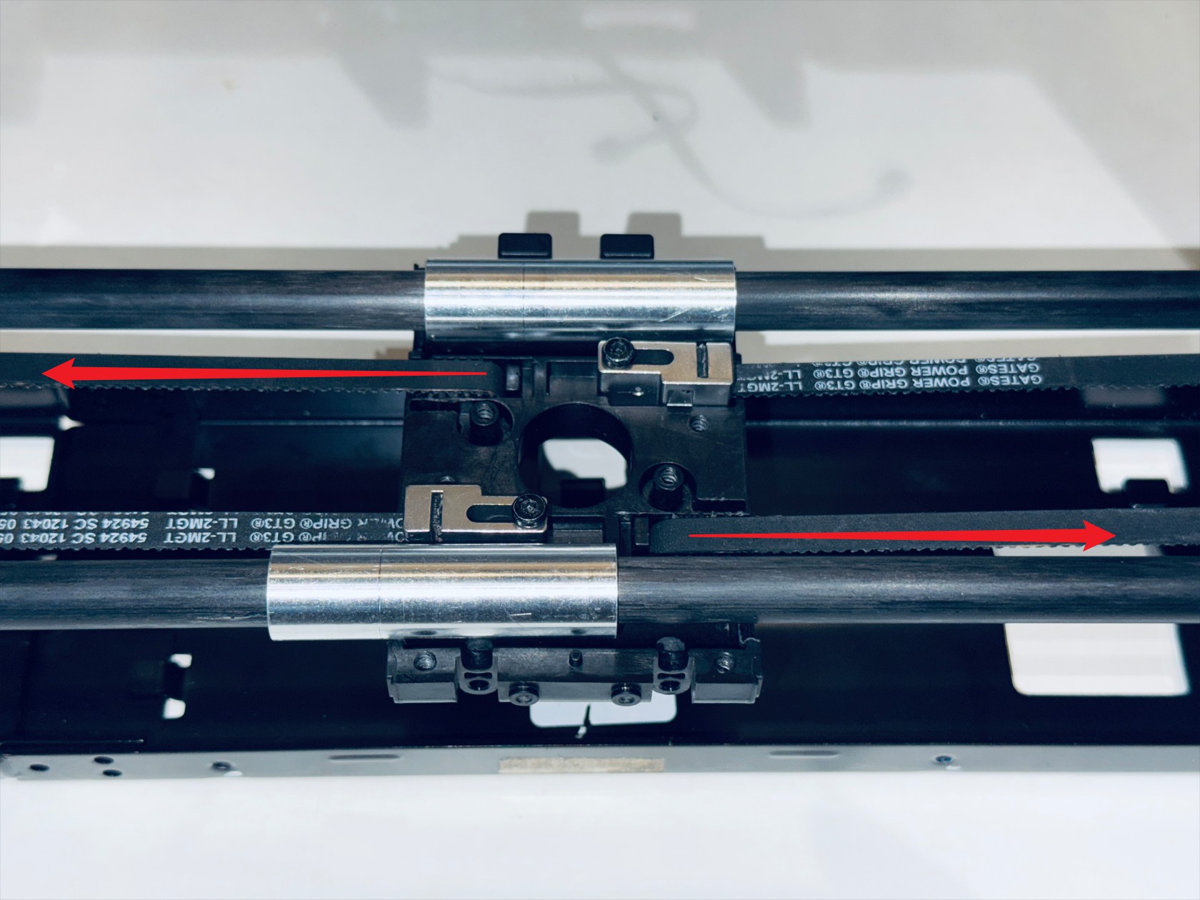
(8) Fix the other timing belt in the same way, then pull both belts in reverse to check if they are secured,* Then cut off the excess part of the timing belts.
(9) Insert the long end of the torsion spring arm into the end tensioning movable block
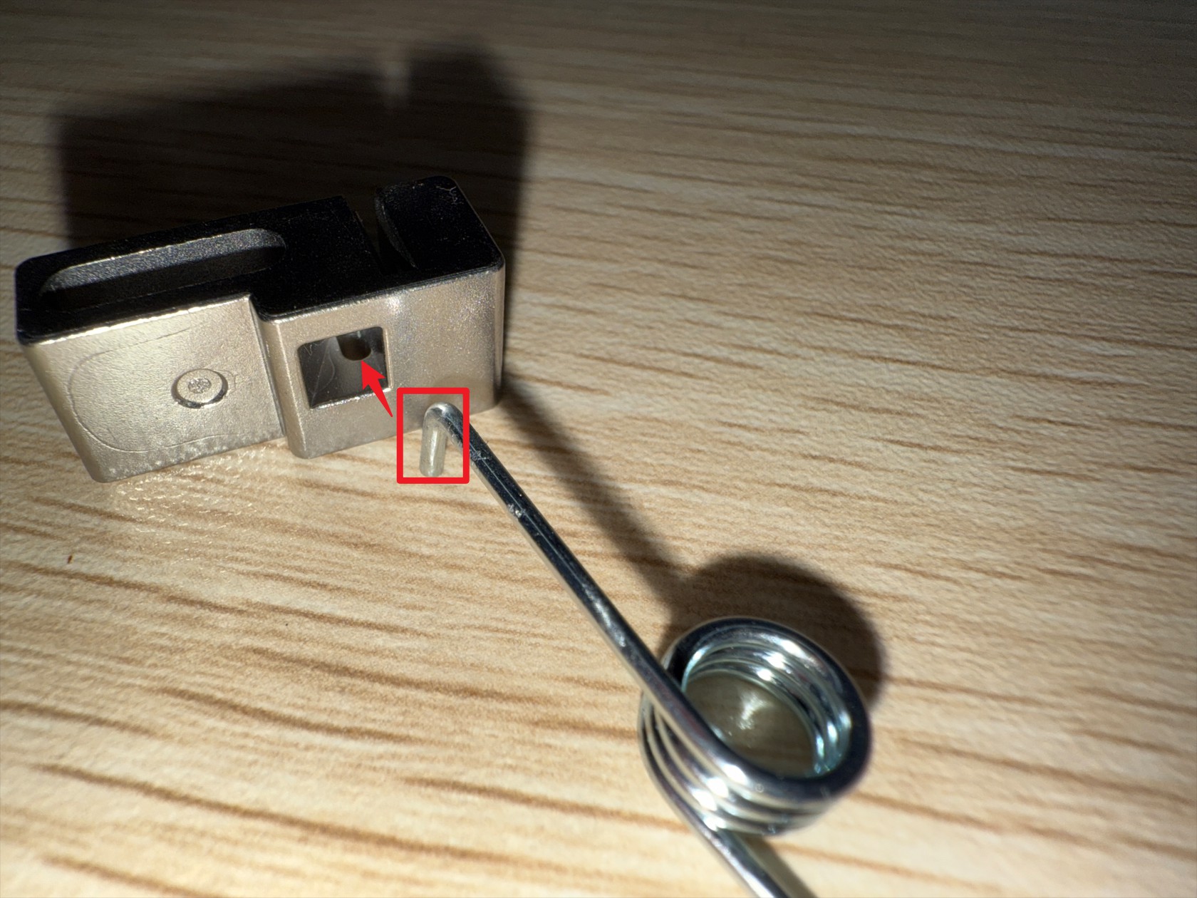
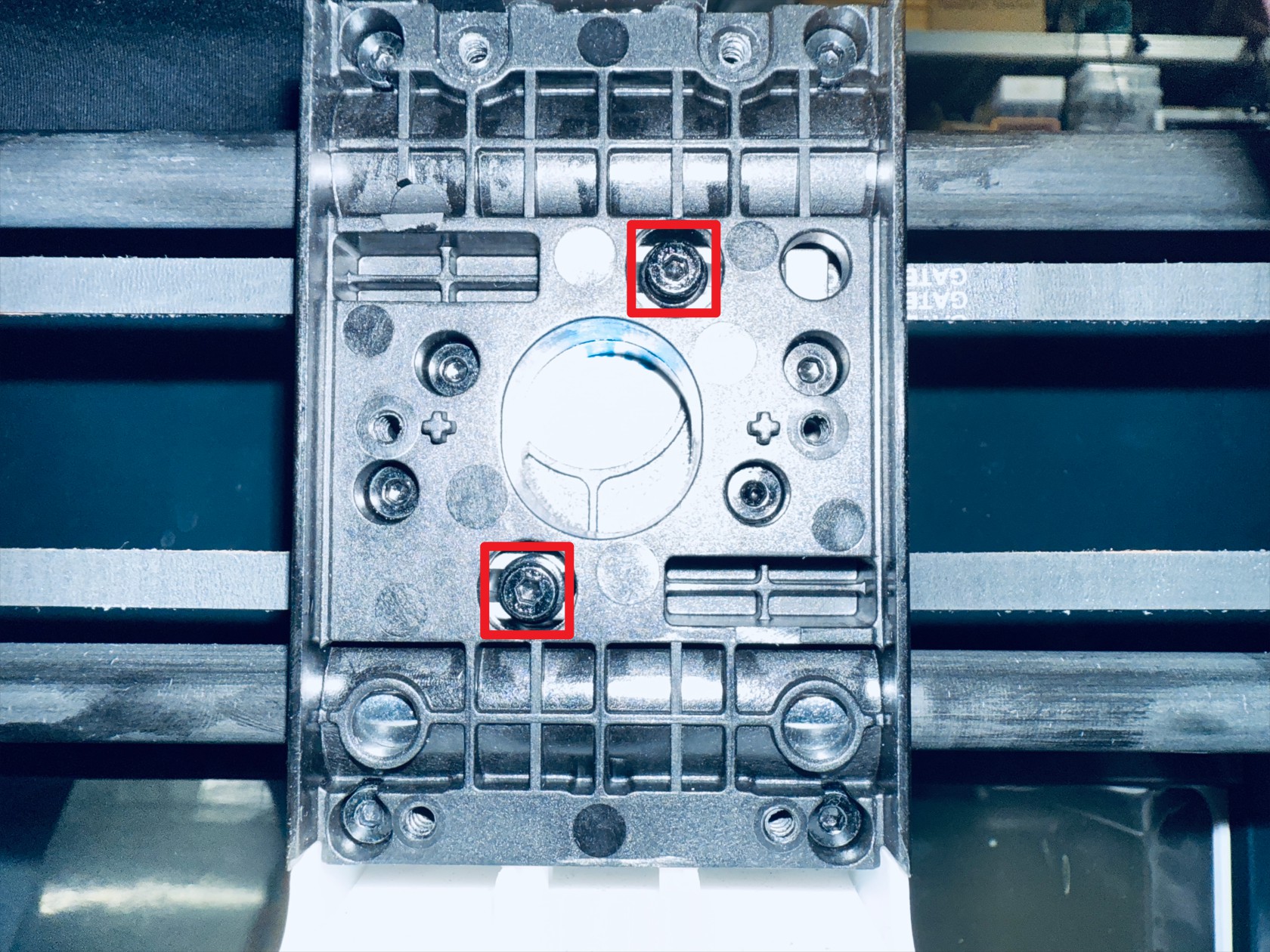
(10) Hook the middle of the torsion spring into the groove post, use an H2.0 hex key to partially tighten 2 screws securing X-axis slider-1 and X-axis slider-2 into the post (about 1/3, to prevent the torsion spring from popping out)
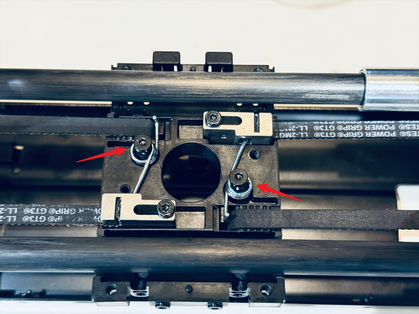
(11) Use strong needle-nose pliers to twist the short end of the torsion spring into the groove, ensure the spring is flush with the groove bottom, and the long arm remains in the middle hole of the movable block, finally remove the screws from the post
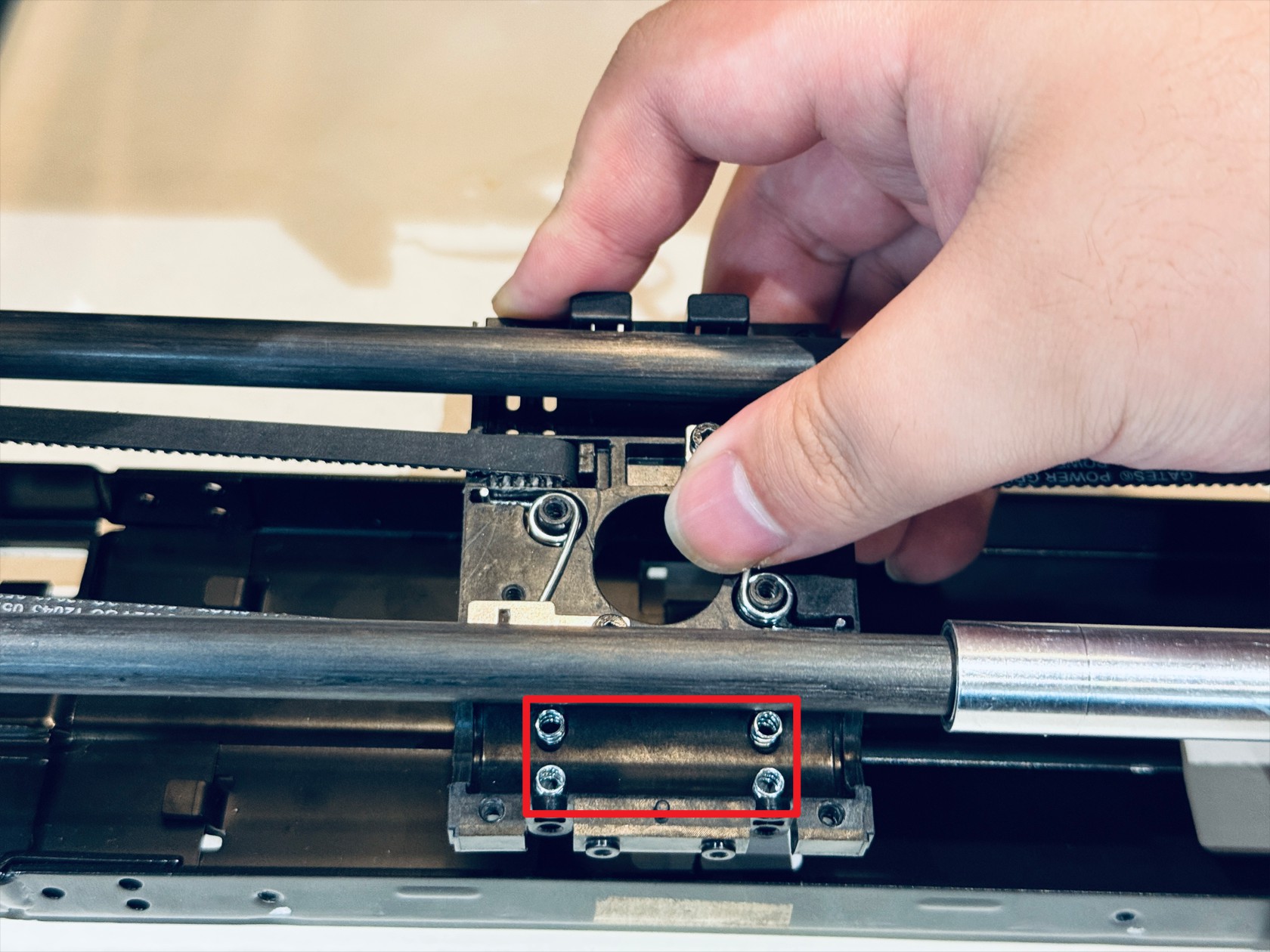
(12) Place 4 anti-backlash springs into the illustrated position of X-axis slider-2. Move the oil-free bearing into the X-axis slider-2 groove, cover with X-axis slider-1, and sequentially tighten 8 screws
(13) Use an H2.0 hex key to loosen the 2 screws of the end tensioning movable block counterclockwise 180°
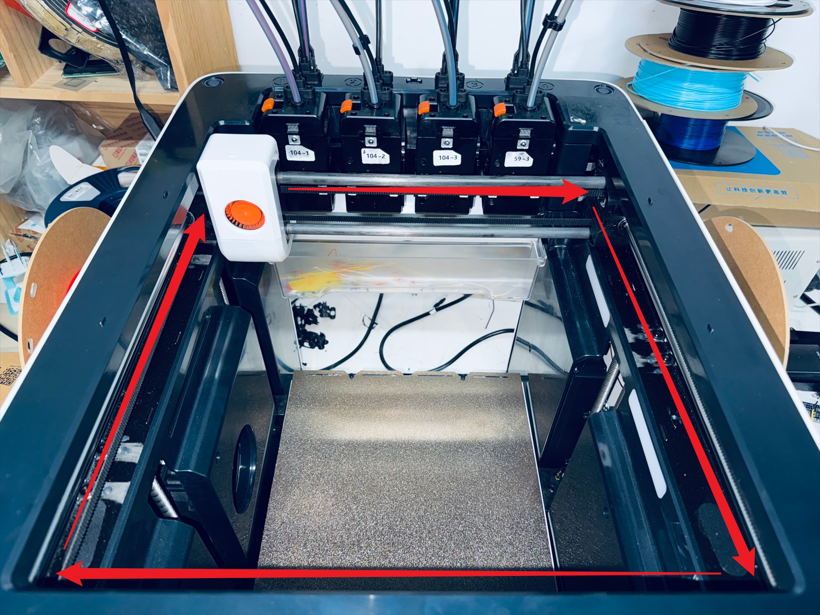
(14) Move X-axis slider along the illustrated path to ensure smooth motion, then use an H2.0 hex key to tighten the 2 screws of the end tensioning movable block
(15) Install the male mount, use an H2.0 hex key to tighten 4 screws
(16) Install the part cooling fan adapter board, use an H1.5 hex key to tighten 4 screws

(17) Install the part cooling fan, restore cables, use an H2.0 hex key to tighten 2 screws
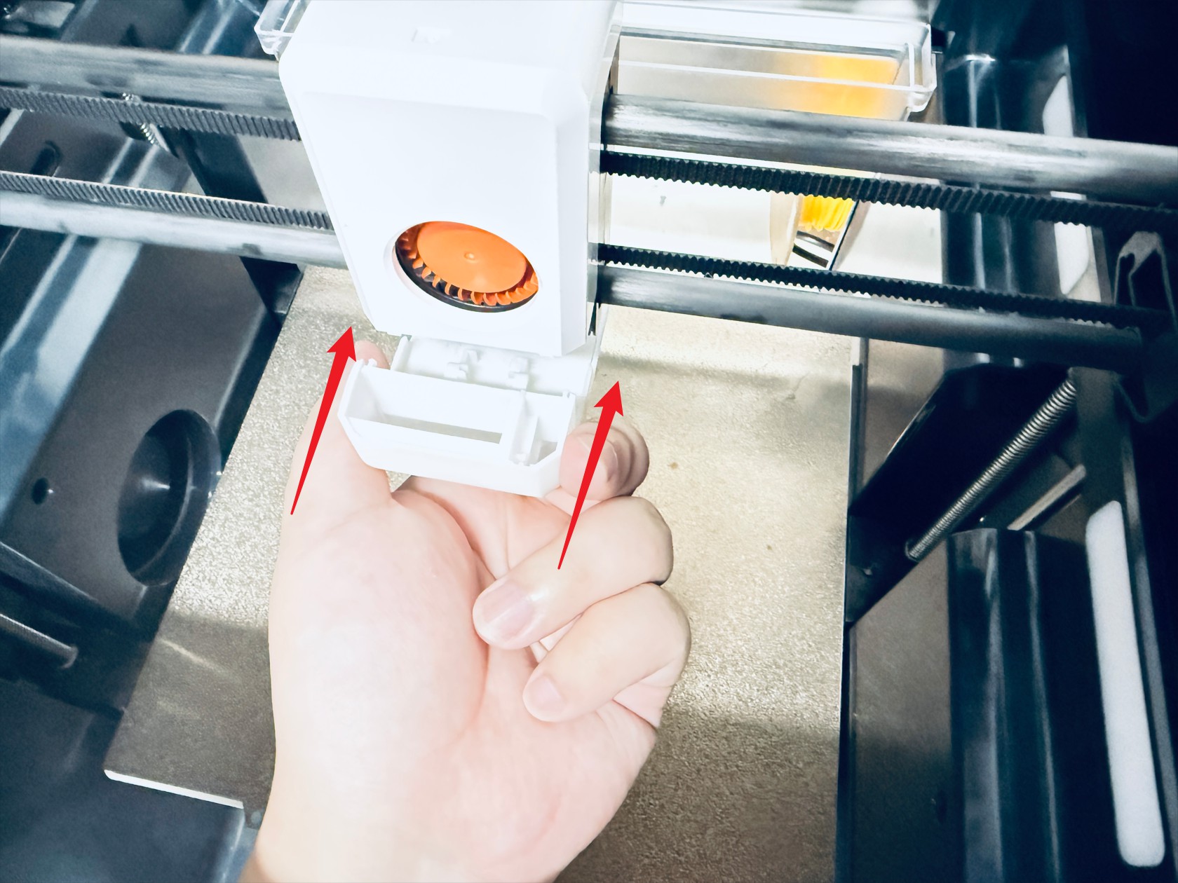
(18) Install the part cooling assembly, use an H2.0 hex key to tighten 2 screws

¶ Reach out to Snapmaker Support
After following the troubleshooting steps, if you find it difficult to resolve your issue, kindly submit a support ticket through https://snapmaker.formcrafts.com/u1-troubleshooting-request and share your troubleshooting results with some pictures/videos.
Our dedicated support team will be more than willing to assist you in resolving the issue.