¶ 💡 Compatibility
This guide applies to the following machine. Please note when referencing:
Machine model: U1
¶ 📝 Issue description
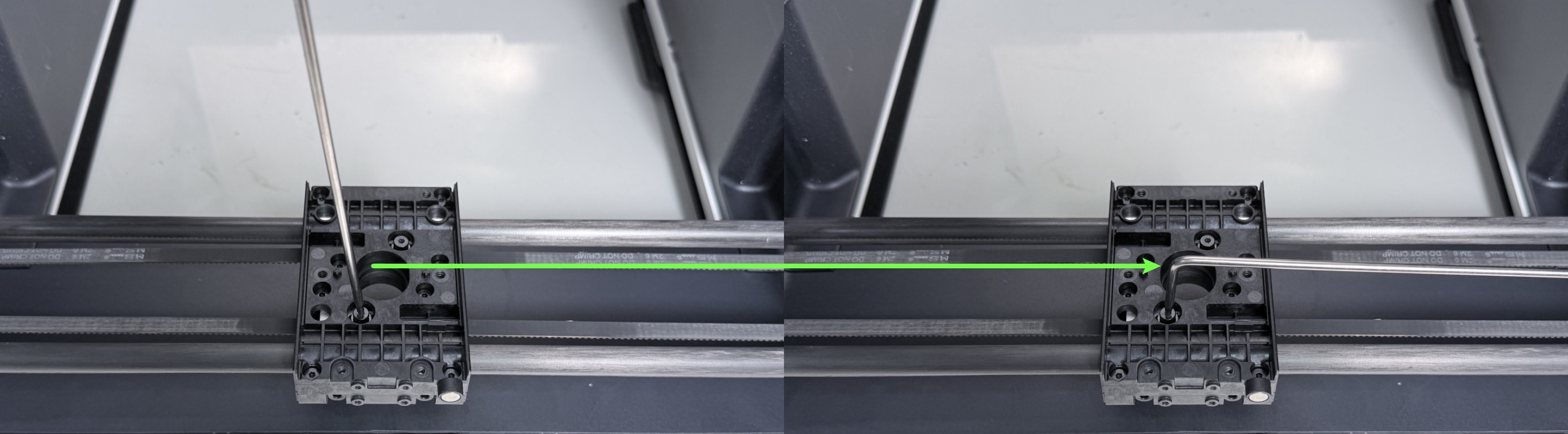
Tips:When you find it difficult to loosen or tighten the screw using the short arm of the L-shaped hex key.
Switching to the long arm will provide more leverage and make the operation easier.
¶ 📋 Quick Info Card
Difficulty: ⭐⭐⭐☆☆ (Easy)
Estimated Time: 20 Minutes
Skill Required: Basic machine disassembly and reassembly.
¶ 🔧 Preparation
| Tools / Material | Quantity |
|---|---|
| Needle-nose pliers | 1 |
| H2.0 hex key | 1 |
| H1.5 hex key | 1 |
| M3×16 hex socket screw | 2 |
¶ 🛠️ Procedure
¶ Part1 - Replace the stripped screws
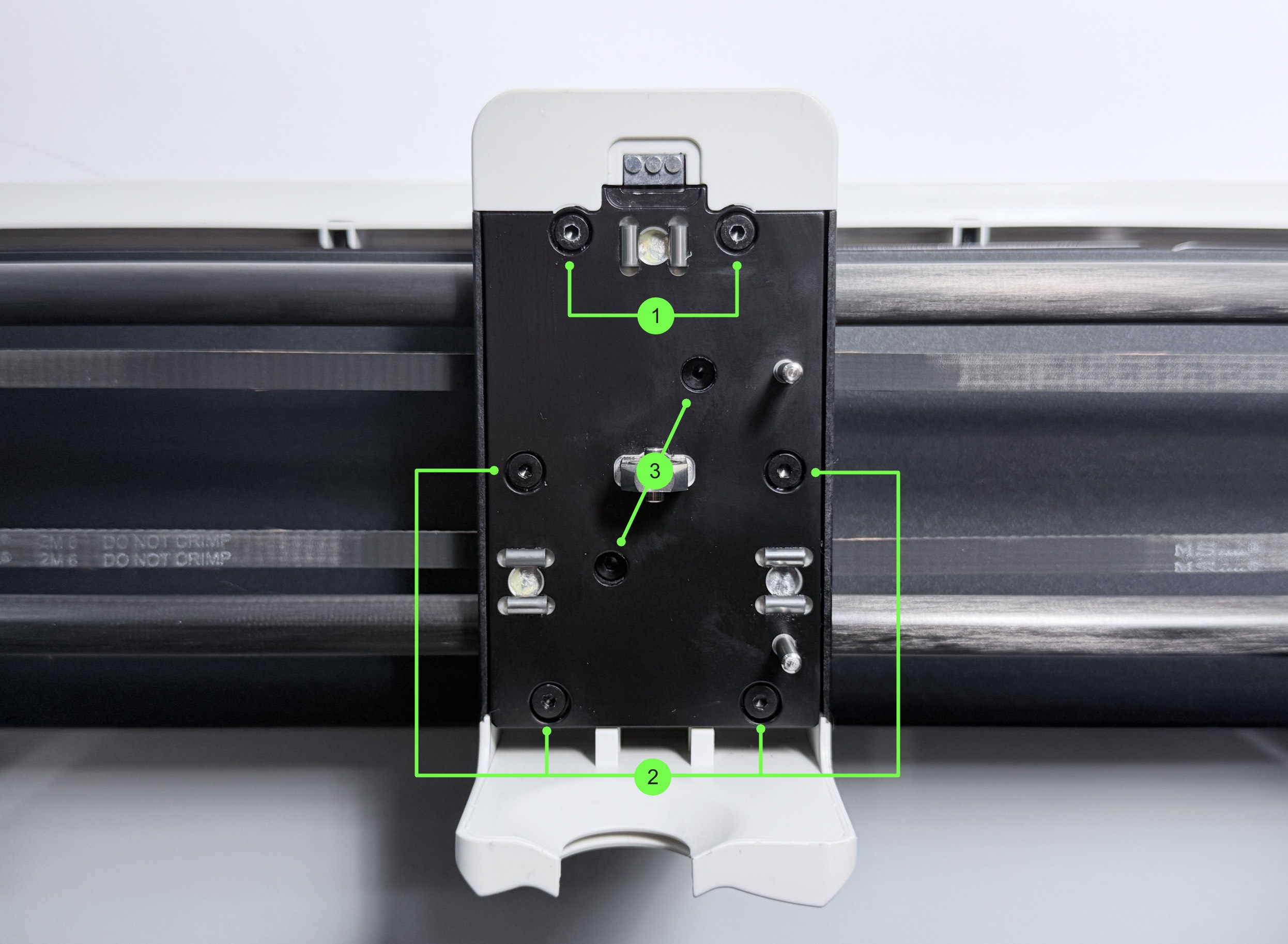
(1) Remove the screws in groups 1 and 2 using an H2.0 hex key.
| Group No. | Screw Specification | Quantity | Location |
|---|---|---|---|
| 1 | ST3 × 8 | 2 | Toolhead female base |
| 2 | ST3 × 8 | 4 | Toolhead female base |
| 3 | M3 × 16 | 2 | XY belt |
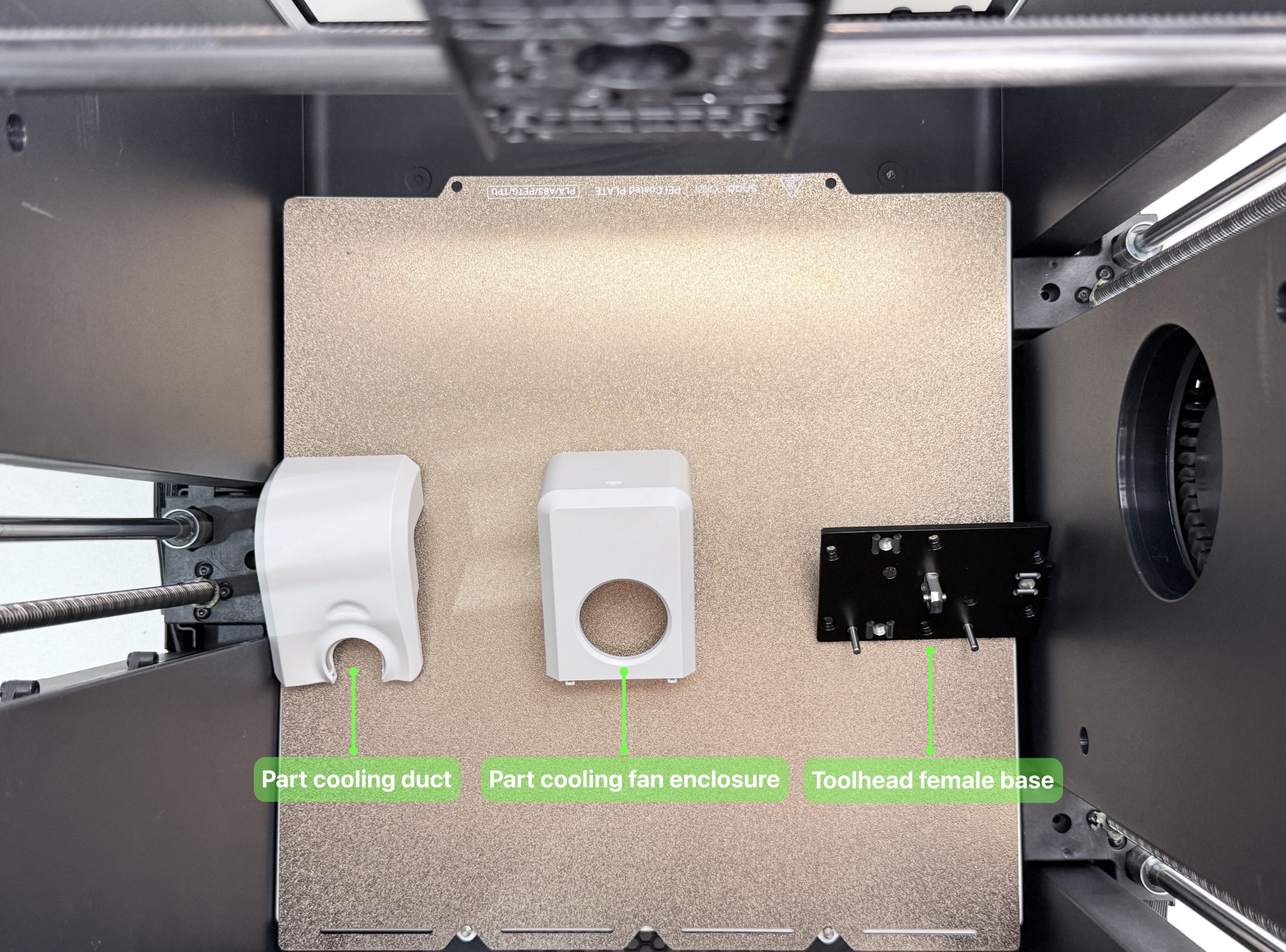
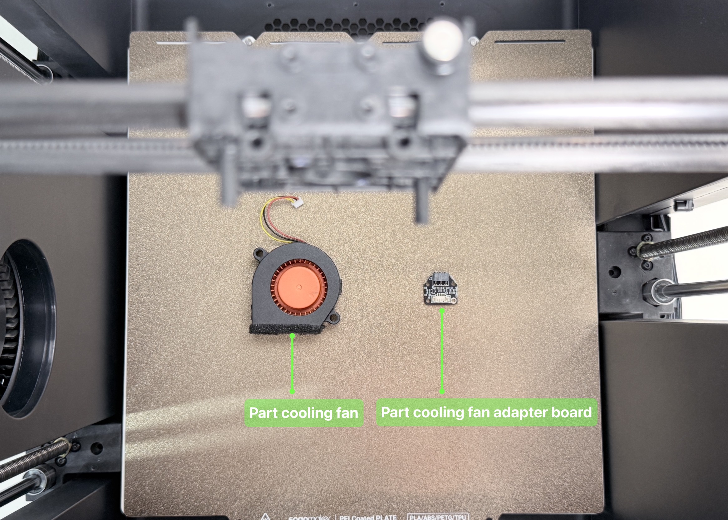
(2) Remove the cooling duct, the part cooling fan enclosure, and the toolhead female base in sequence.
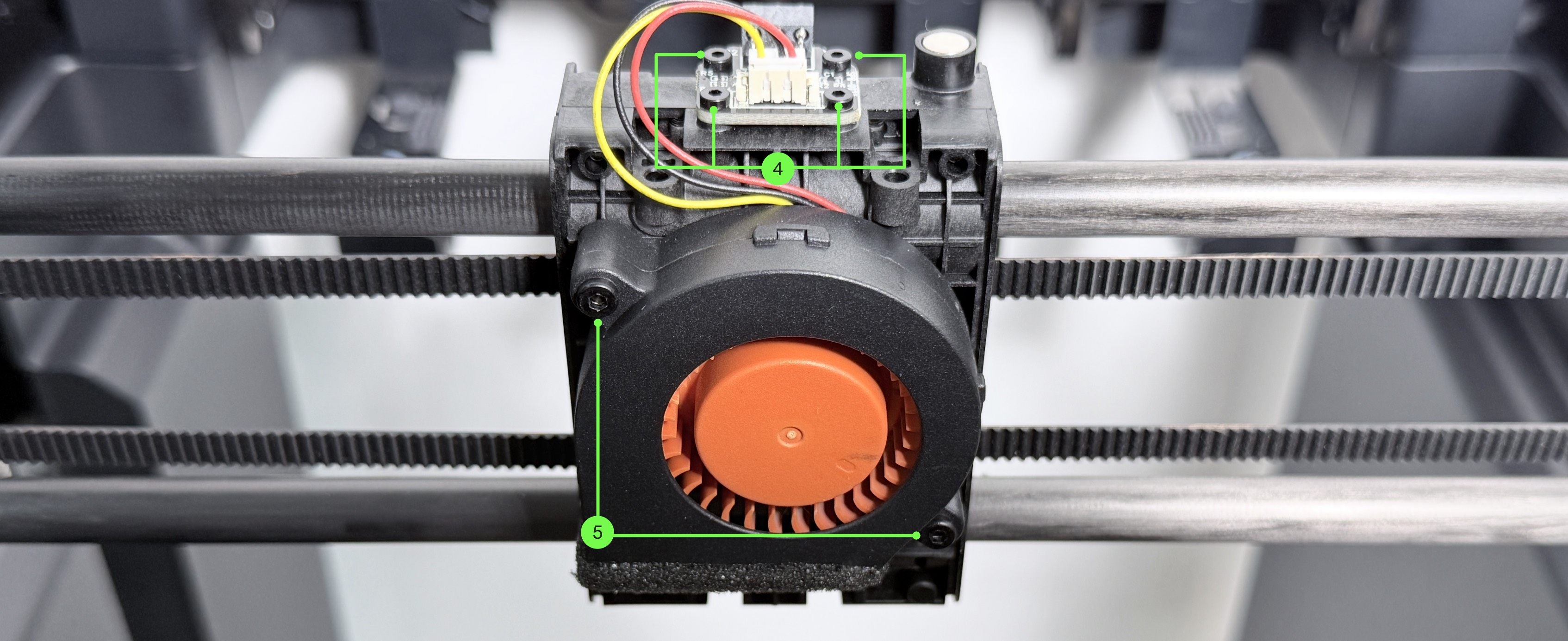
(3) Disconnect the part cooling fan cable. Use H1.5 and H2.0 hex keys to remove the screws in groups 4 and 5, then remove the part cooling fan adapter board and the part cooling fan in sequence.
| Group No. | Screw Specification | Quantity | Location |
|---|---|---|---|
| 4 | ST2 × 6 | 4 | Part cooling fan adapter board |
| 5 | ST2.6 × 10 | 2 | Part cooling fan |
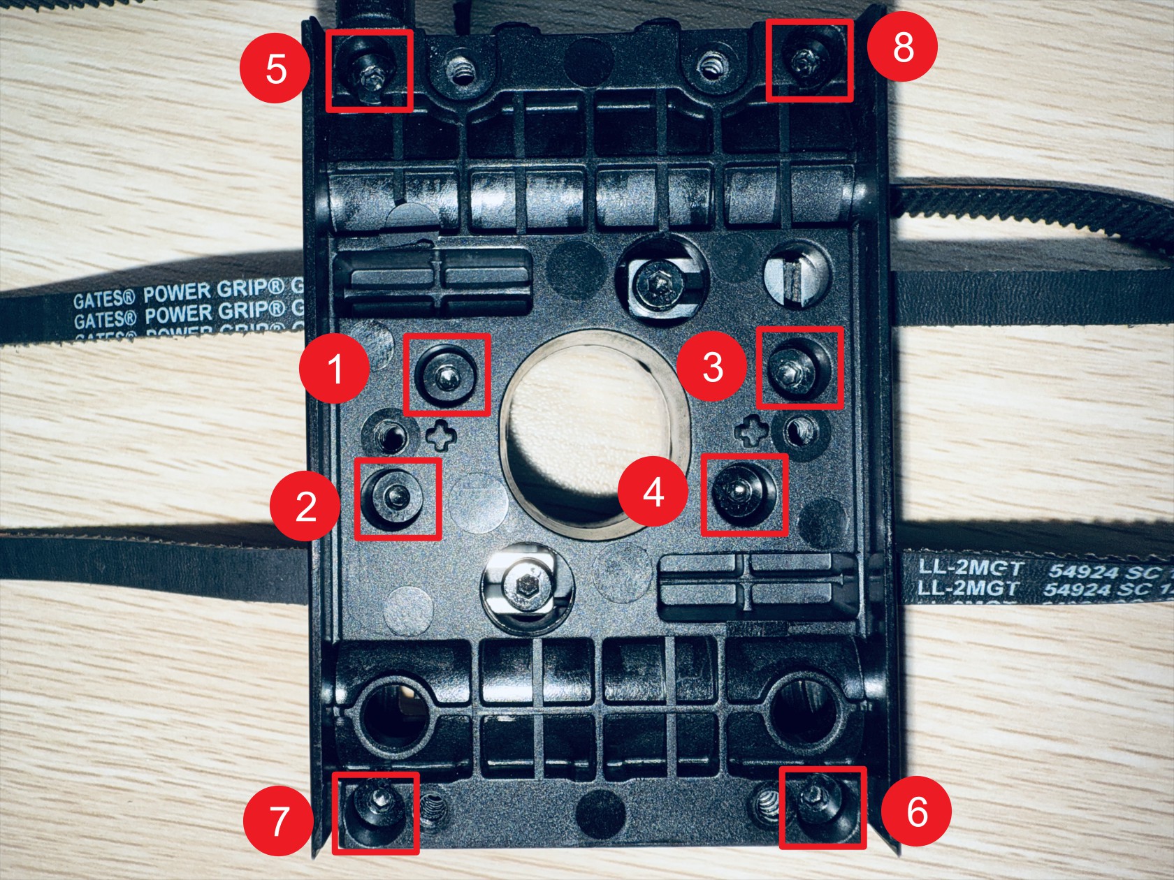
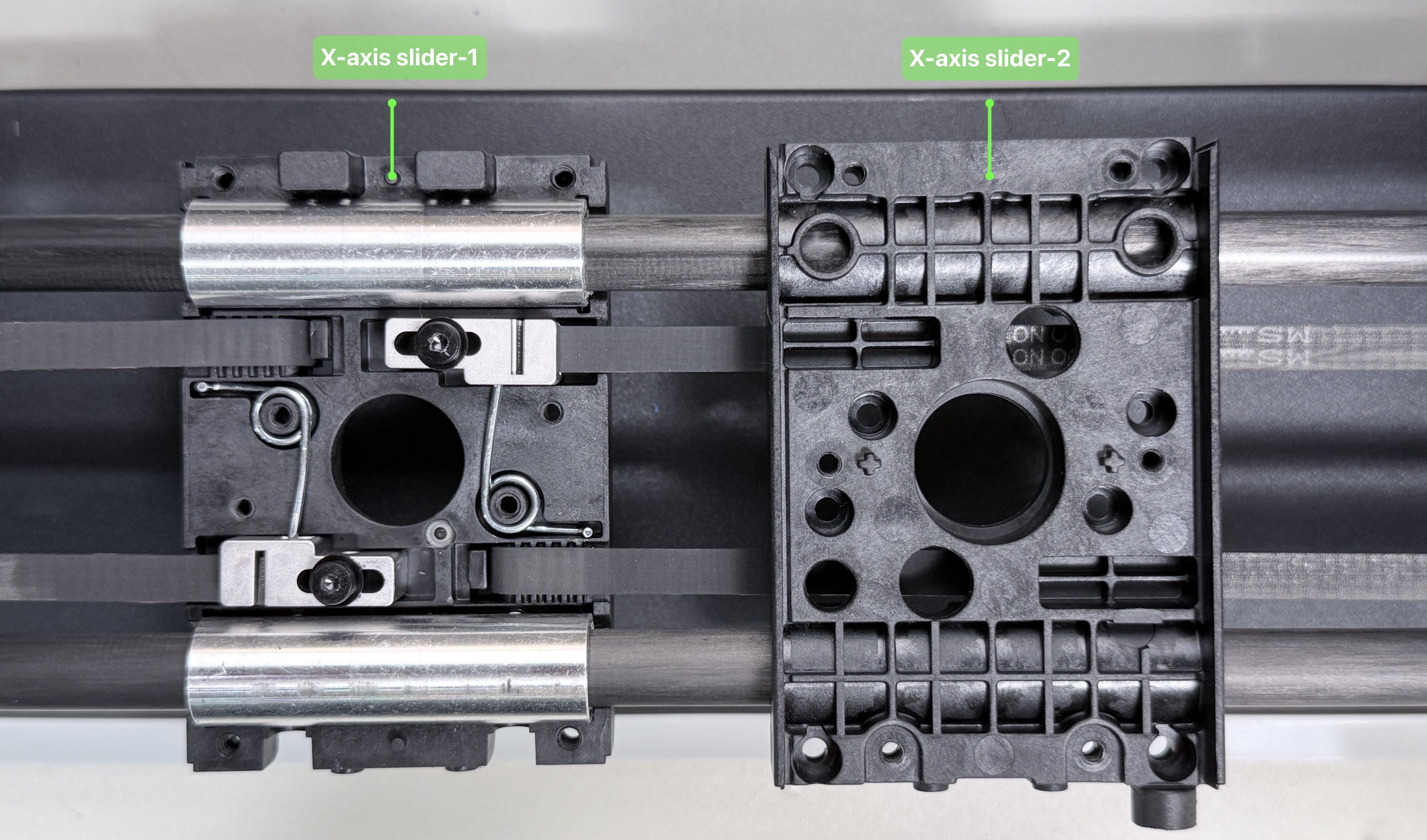
(4) Place the machine face down. Use an H2.0 hex key to remove the screws in group 6, then remove X-axis slider-2.
| Group No. | Screw Specification | Quantity | Location |
|---|---|---|---|
| 6 | ST3 × 10 | 8 | X-axis slider |
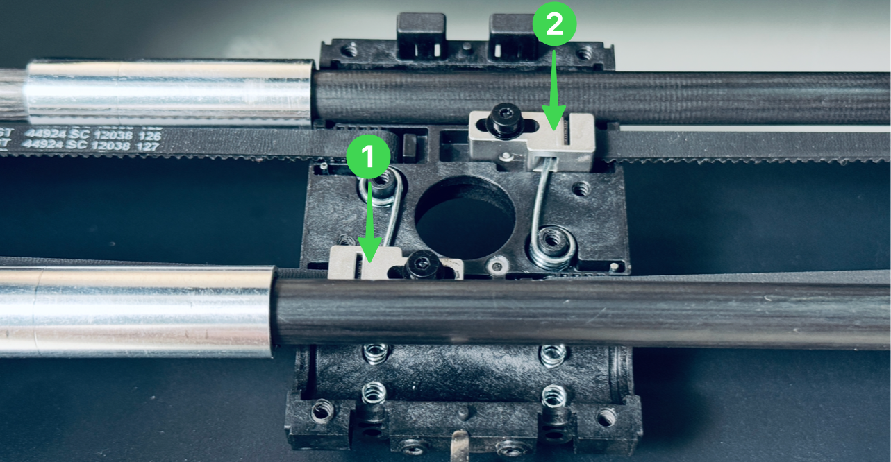
There are 4 springs beneath the oil-free bearing, please be careful not to lose them.
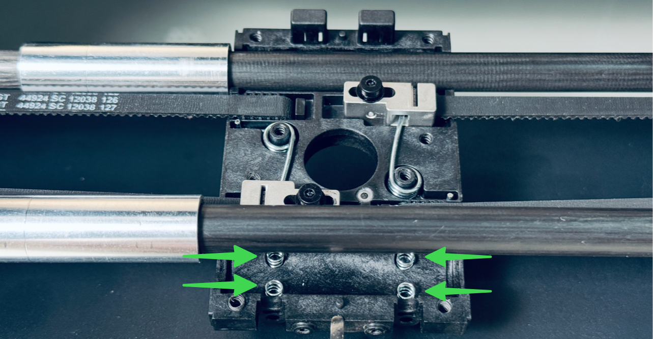
(5) Use needle-nose pliers to grip the screw head and remove it. Replace it with a new M3×16 hex socket screw.
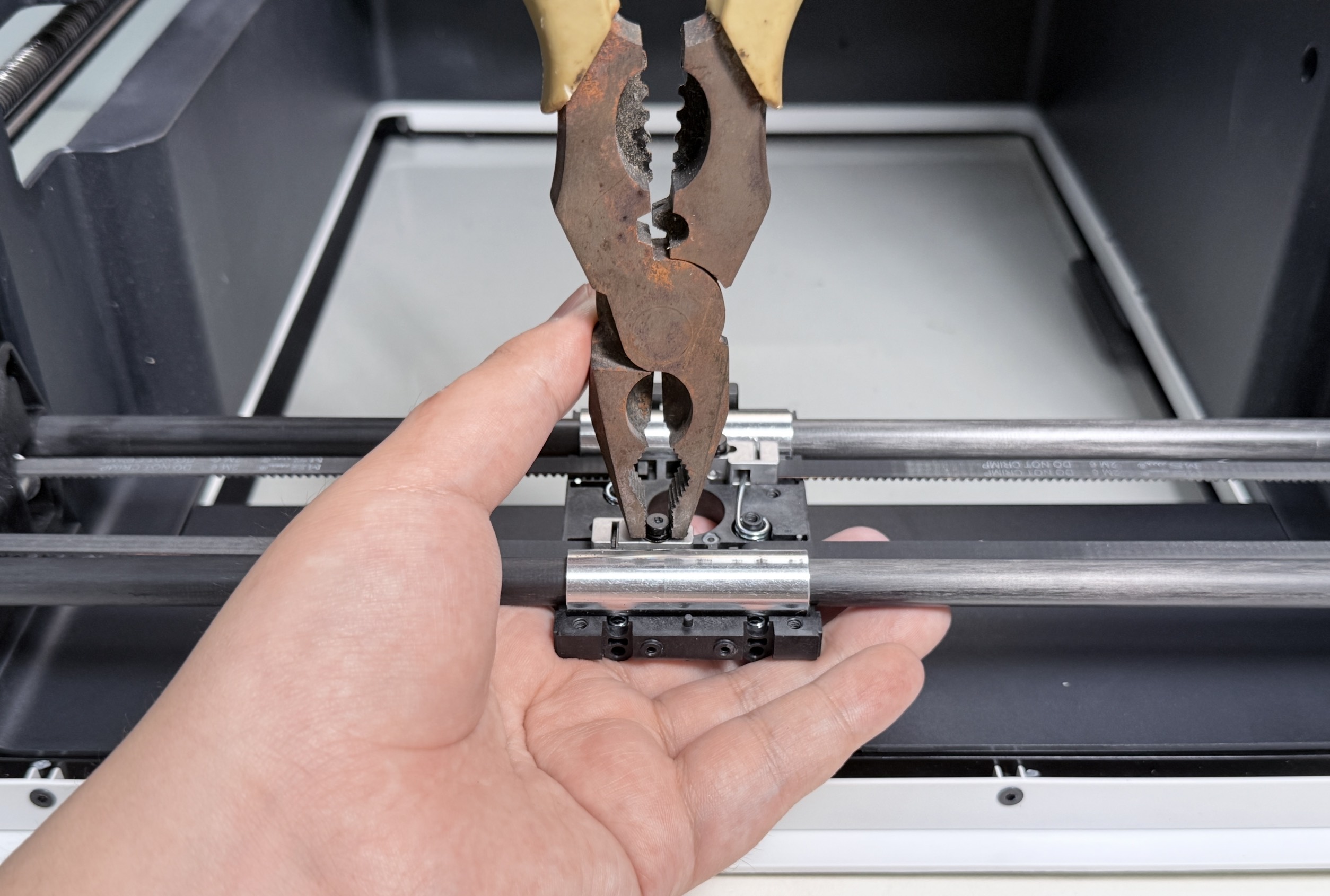
When loosening the screws, please hold down the corresponding metal block to prevent it from being ejected by the torsion spring.
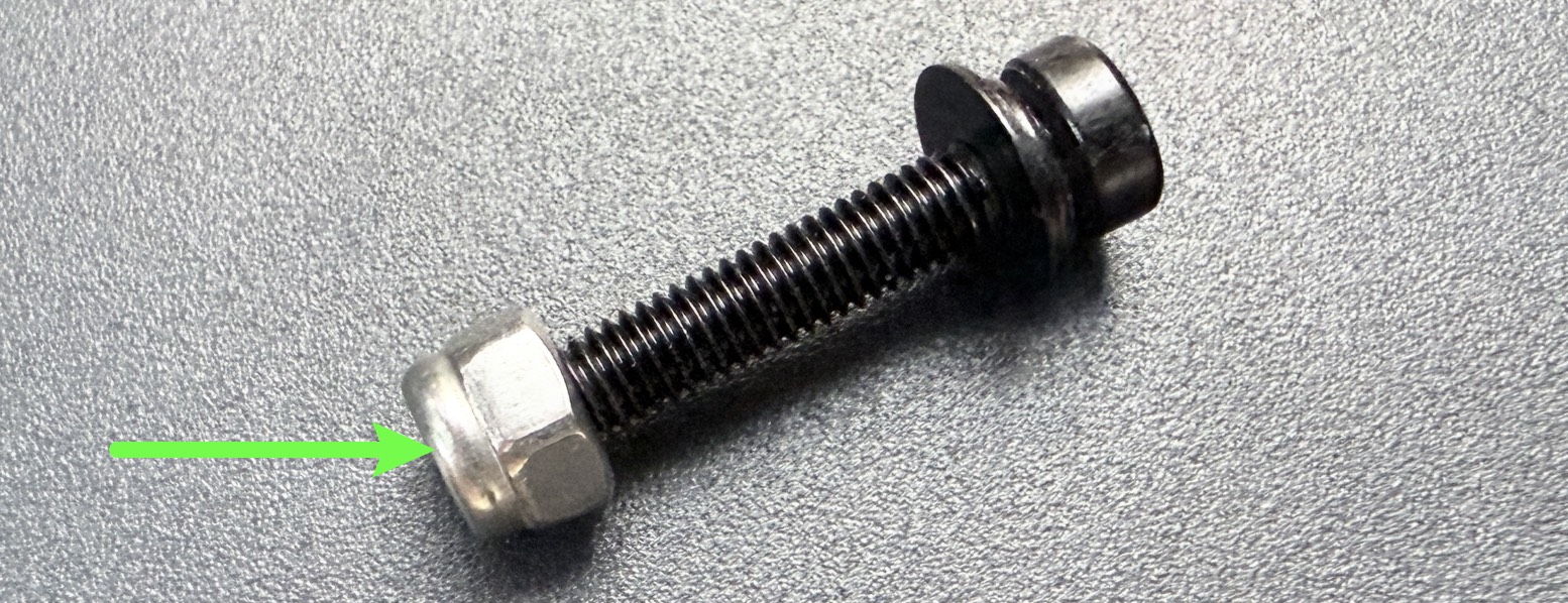
The corresponding nut is located on the underside of X-axis slider-1 and is not secured.
Please take care not to lose it.
¶ Part2 - Restore toolhead swapper
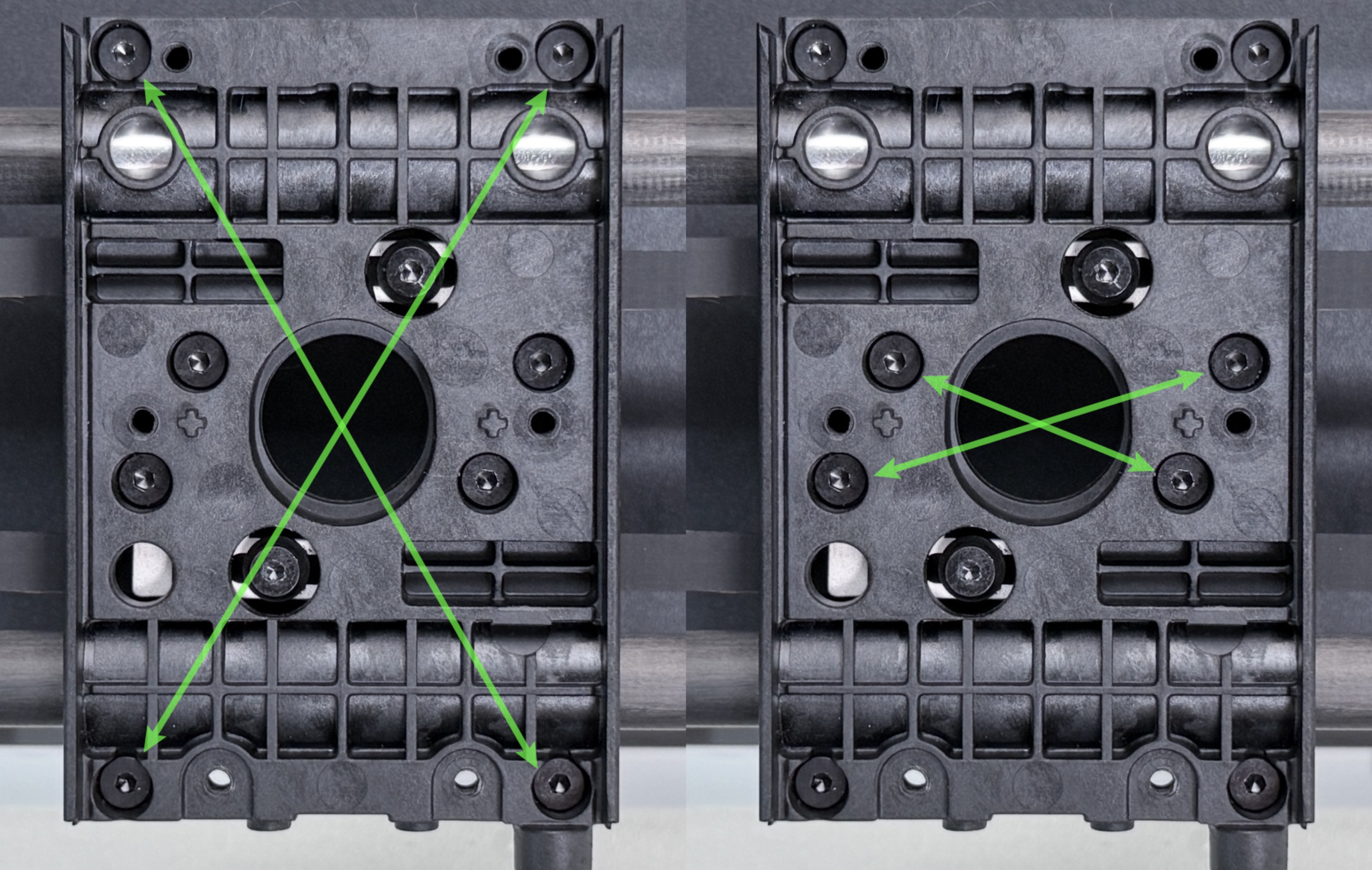
(1) Place X-axis slider-2 onto slider-1. Use an H2.0 hex key to pre-tighten the screws in group 6 in a diagonal sequence, then fully tighten them.
| Group No. | Screw Specification | Quantity | Location |
|---|---|---|---|
| 6 | ST3 × 10 | 8 | X-axis slider |
(2) Install the part cooling fan and adapter board. Use H1.5 and H2.0 hex keys to tighten the screws in groups 4 and 5, then reconnect the fan cables.
| Group No. | Screw Specification | Quantity | Location |
|---|---|---|---|
| 4 | ST2 × 6 | 4 | Part cooling fan adapter board |
| 5 | ST2.6 × 10 | 2 | Part cooling fan |
(3) First install the toolhead female base and tighten the screws in group 2 using an H2.0 hex key. Then install the part cooling fan enclosure and the cooling duct in sequence, and tighten the screws in group 1.
| Group No. | Screw Specification | Quantity | Location |
|---|---|---|---|
| 1 | ST3 × 8 | 2 | Toolhead female base |
| 2 | ST3 × 8 | 4 | Toolhead female base |
| 3 | M3 × 16 | 2 | XY belt |
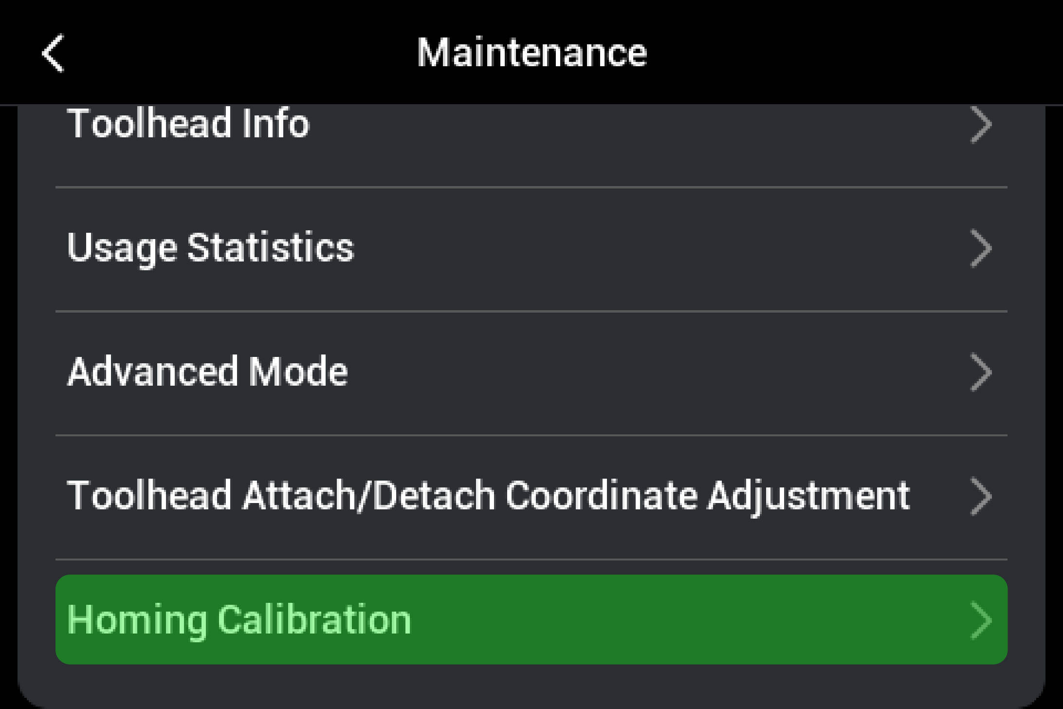
¶ Part3 - Homing calibration
Perform homing calibration in Settings → Maintenance.
¶ 💬 Reach out to Snapmaker Support
After following the troubleshooting steps, if you find it difficult to resolve your issue, kindly submit a support ticket through https://snapmaker.formcrafts.com/u1-troubleshooting-request and share your troubleshooting results with pictures or videos.
Our dedicated support team will be more than willing to assist you in resolving the issue.