¶ Overview
In a CoreXY structure, the X and Y motors do not correspond to the X and Y axis respectively.
Both motors always work together, achieving toolhead movement in the X and Y directions through different combinations of rotation direction and speed.
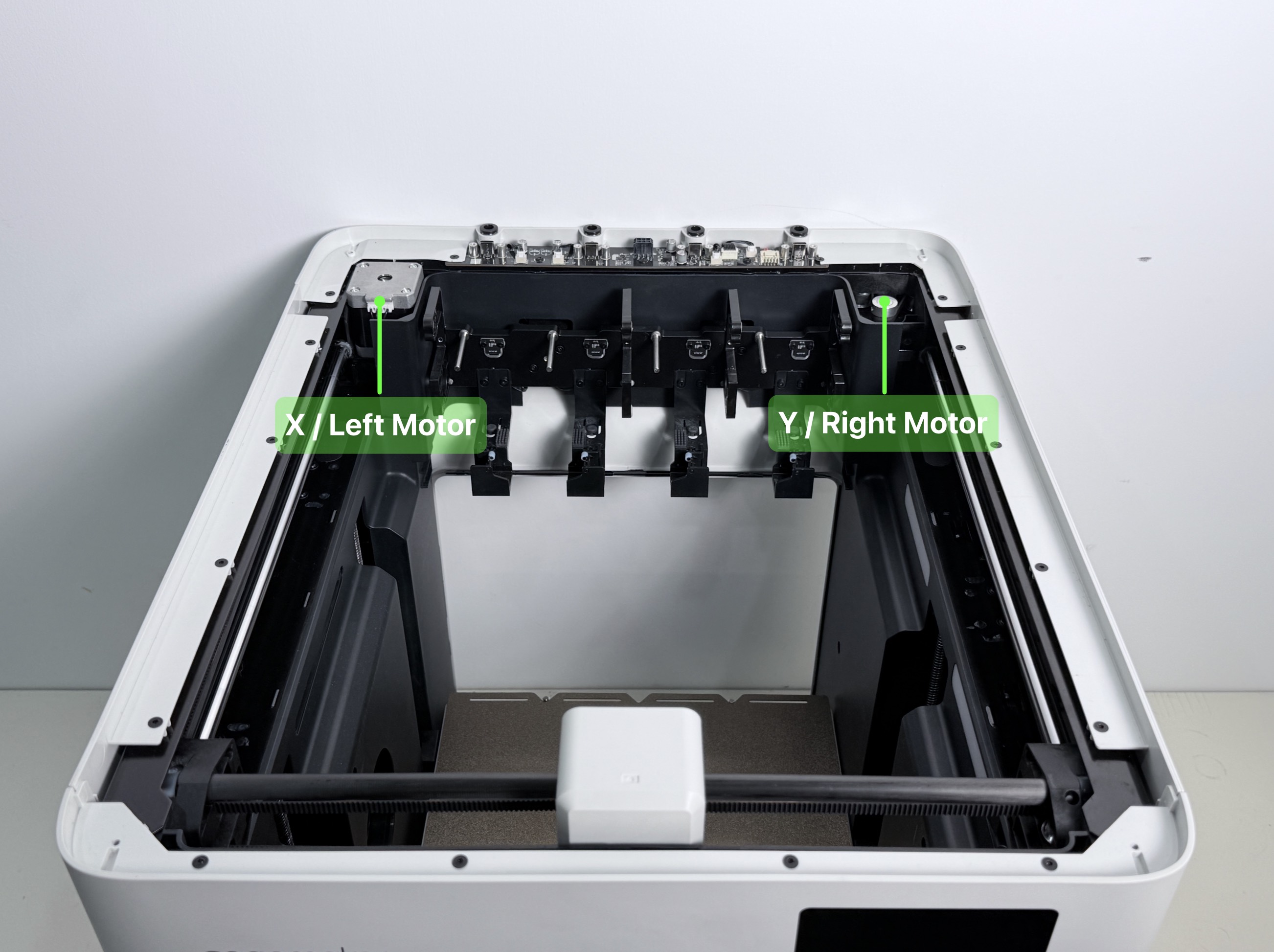
¶ Location
¶ Difficulty
Difficulty: ⭐️⭐️⭐️⭐️⭐️
Estimated Time: 120 min
¶ Preparation
¶ Procedure
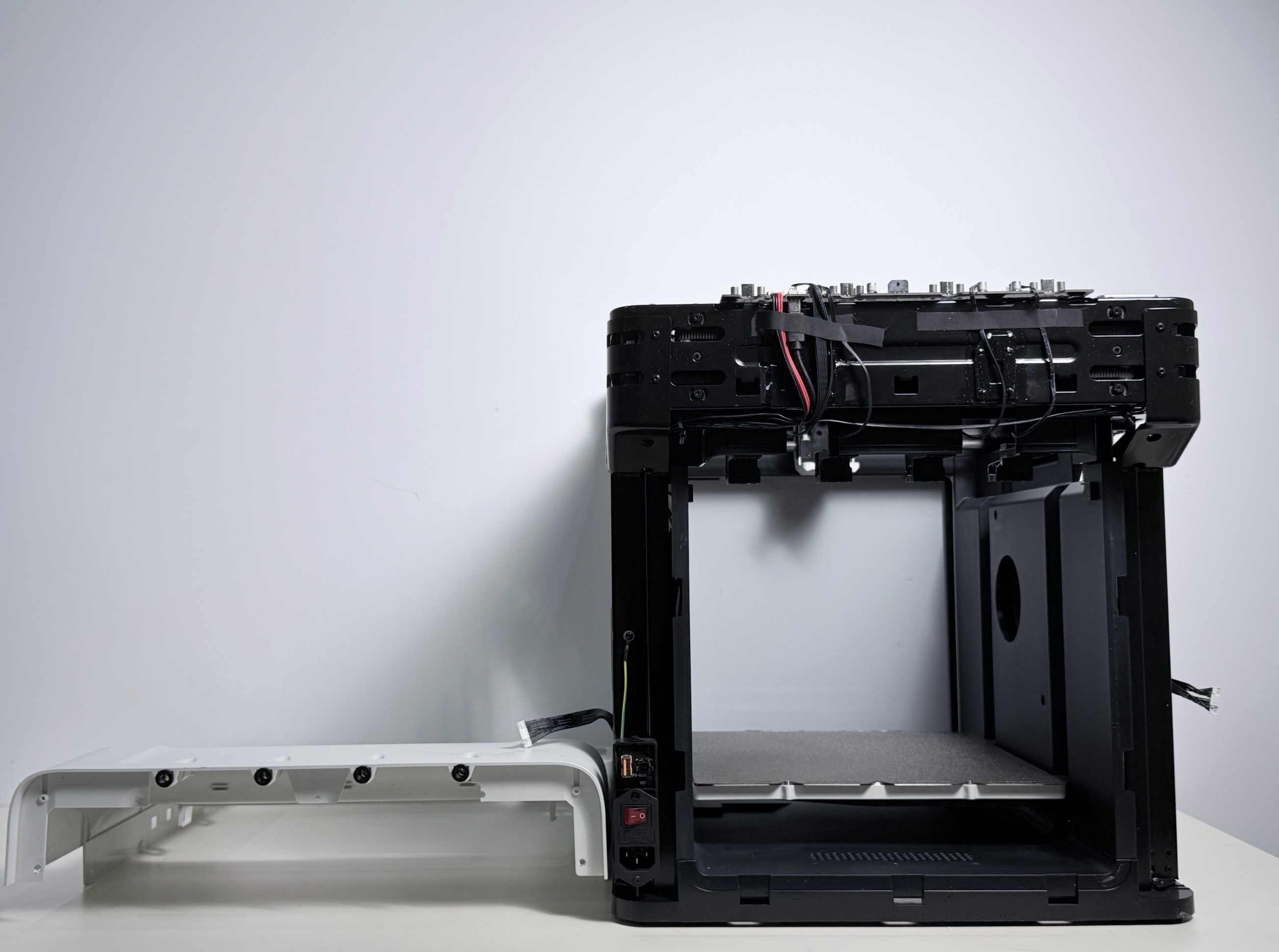
¶ 1. Remove the Machine Panels
Refer to the Hub Board Replacement Guide to remove the machine panels, including the top panel, left and right side panels, and rear cover.
Some steps are easier to perform with the machine upside down, so it is recommended to remove the Hub board at the same time.
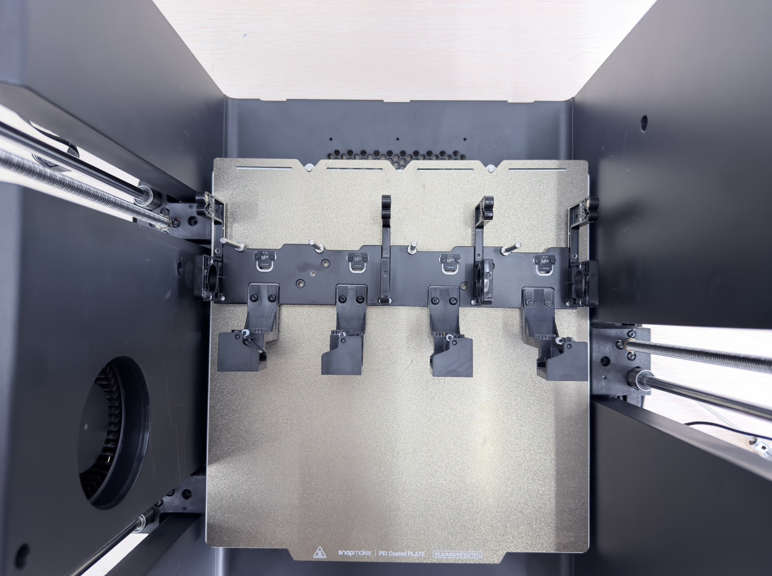
¶ 2. Remove the Docking Bracket Assembly
Refer to the Toolhead Docking Bracket Replacement Guide to remove the toolhead docking bracket assembly.
¶ 3. Release the Timing Belt
(1) Refer to XY Belt Tensioner Screw Stripping to disassemble the toolhead swapper, separate X-axis Slider-1 from X-axis Slider-2, and remove the 4 anti-backlash springs.
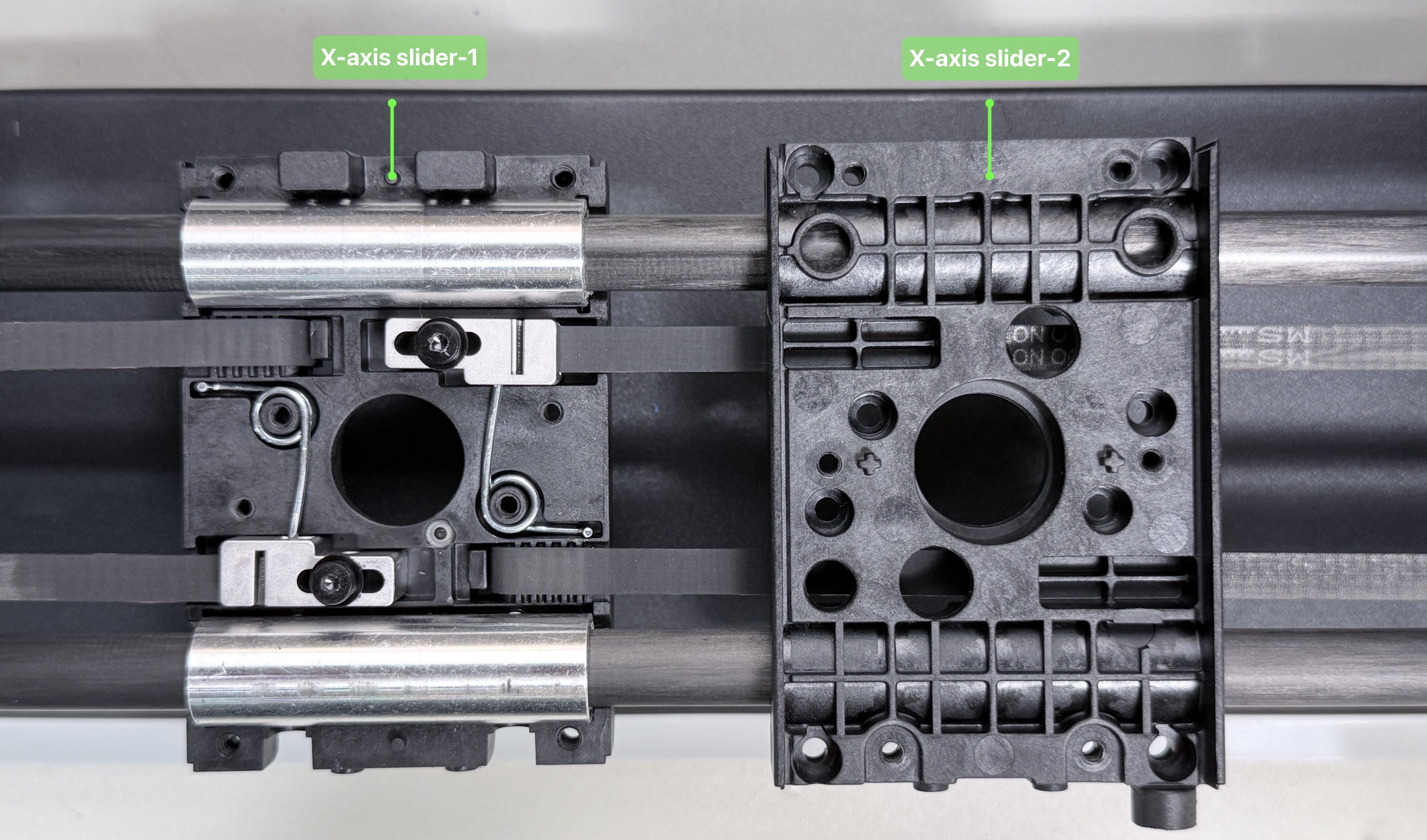
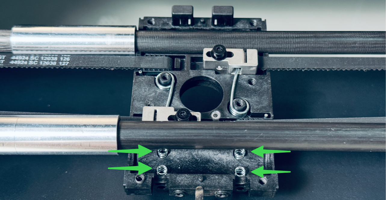
(2) Use an H2.0 hex key to push the belt anchor block out from the back of X-axis Slider-1 to release the timing belt.
(3) Use a zip tie to secure the timing belt to the X axis to prevent it from slipping out of the idler pulleys.
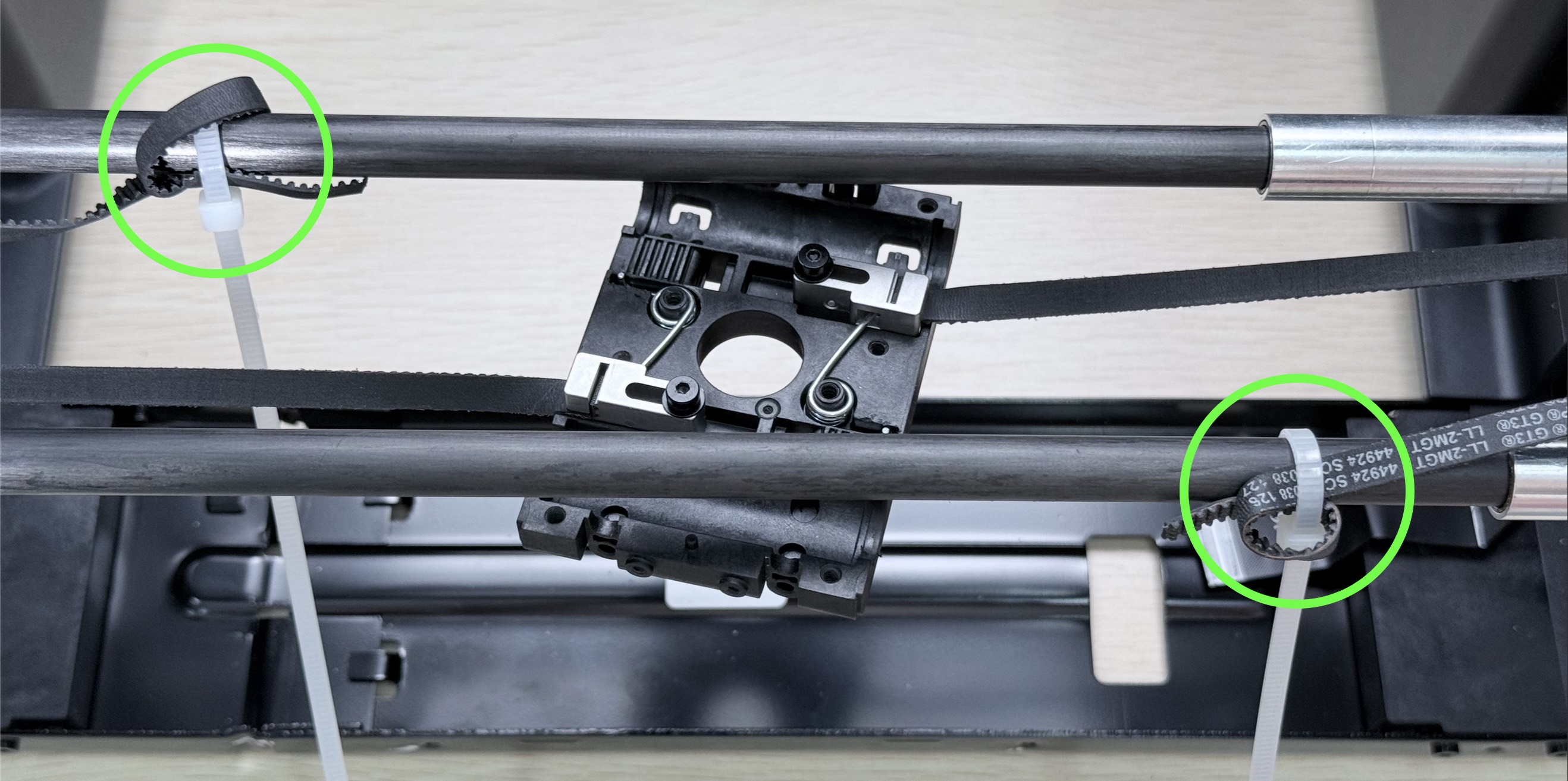
If the timing belt slips out of the idler pulleys due to not being secured, refer to the U1 XY Timing Belt Routing Guide to re-route the belt.
¶ 4. Replace the XY Motors
Replace the X / Left Motor
(1) Disconnect the motor cable.

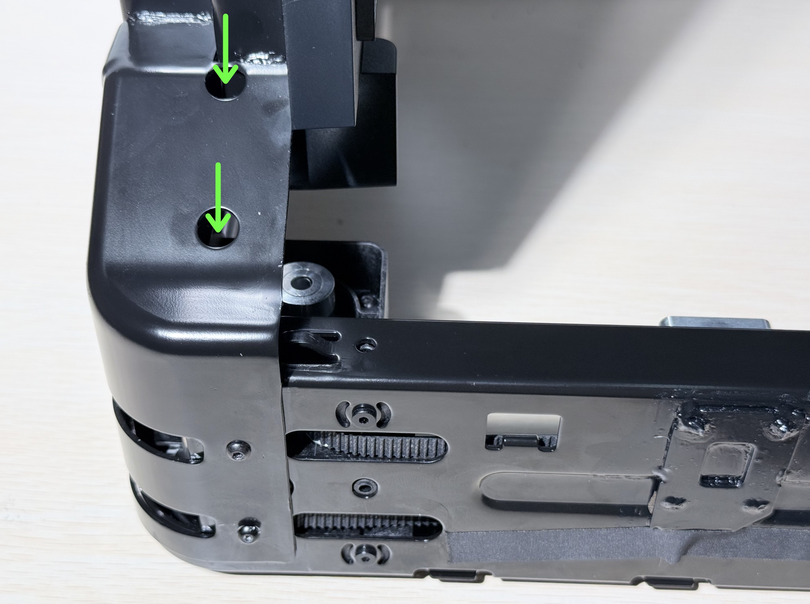
(2) Flip the machine upside down for easier access. Use an H2.0 hex key to remove the 4 screws at the bottom of the motor and take out the old motor.
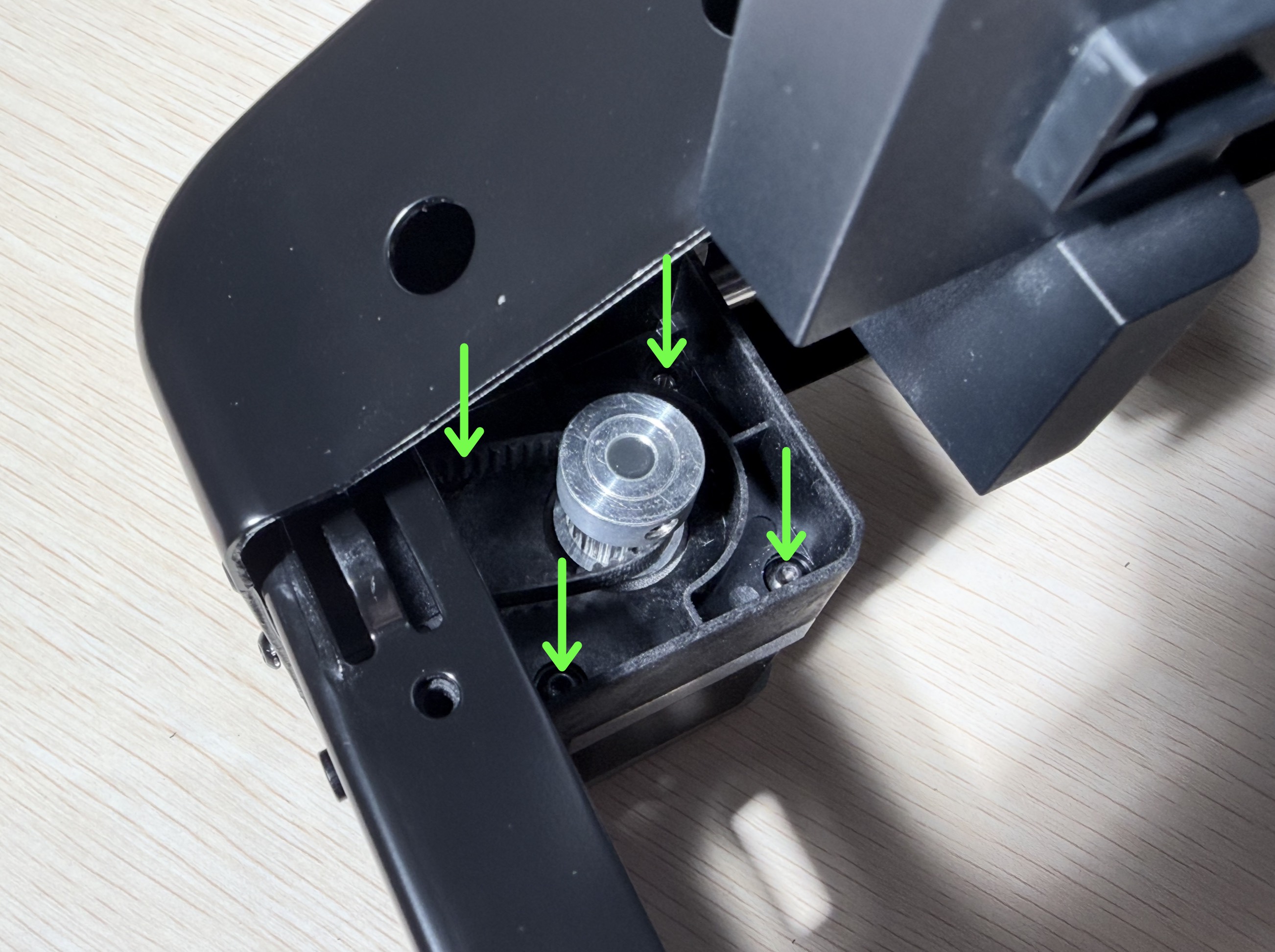
The sheet metal frame has pre-cut access holes for inserting tools to remove the screws.
(3) Install the new motor. Make sure the toothed side of the belt is in contact with the motor pulley.
(4) Tighten the screws and reconnect the motor cable.
Replace the Y / Right Motor
(1) Use tweezers to assist with disconnecting the motor cable.
(2) Use an H2.0 hex key to remove the 4 screws at the top of the motor and take out the old motor.
(3) Install the new motor. Make sure the toothed side of the belt is in contact with the motor pulley.
(4) Reconnect the motor cable and tighten the screws.
¶ 5. Reassemble the Machine
(1) Refer to How to Reinstall the Timing Belt to install the belt anchor block and reassemble the toolhead swapper.
(2) Refer to the Toolhead Docking Bracket Replacement Guide to reinstall the toolhead docking bracket assembly.
(3) Refer to the Hub Board Replacement Guide to reinstall the machine panels and restore the machine.
It is recommended to re-run all items under the Device Calibration page after replacing the XY motors.
¶ Endnote
If the issue persists, please contact technical support.
Our dedicated support team will be more than willing to assist you in resolving the issue.
If you have any suggestions or feedback about this article, feel free to leave a comment below. Every piece of feedback helps us improve our documentation.