¶ Compatibility
This article applies to the following model and module. Please take note when referencing:
Model: U1
¶ Error Codes
This troubleshooting guide applies when the screen displays the following error codes:
| 0002-0523-0000-0021 | 0002-0523-0000-0022 |
| 0002-0523-0000-0023 | 0002-0523-0000-0024 |
| 0002-0523-0000-0025 | 0002-0523-0000-0026 |
| 0002-0523-0000-0027 | 0002-0523-0000-0028 |
| 0002-0523-0000-0029 | 0002-0523-0000-0030 |
| 0002-0523-0000-0031 | 0002-0523-0000-0032 |
| 0002-0523-0000-0033 | 0002-0523-0000-0034 |
| 0002-0523-0000-0035 |
¶ Issue Description
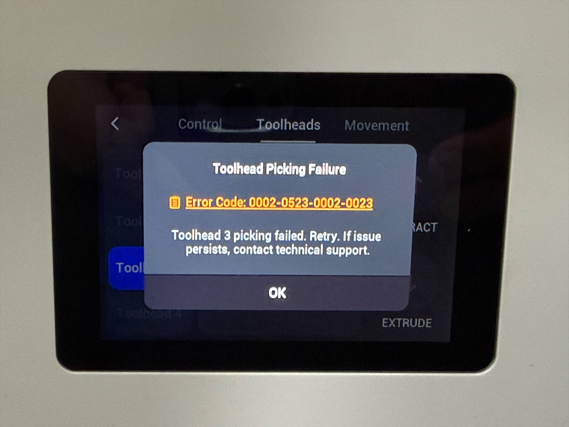
- The printing process stops unexpectedly, and the screen displays an "Toolhead Picking Failure" error message.
¶ Terminology
Different from our official term, some people may use the following terms to describe the machine’s toolhead pick and park process:
- Pick and dock
- Attach and detach
- Pick and drop
- Take and park
- Take and return
¶ Possible Causes
-
It may be caused by a homing failure.
-
The toolheads are misplaced.
-
The pogo pin contacts are dirty.
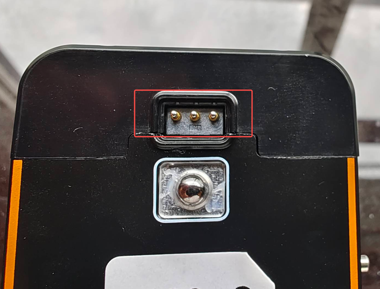
- The pogo pins are not making proper contact or are severely worn out.
¶ Troubleshooting and Solutions
¶ Step 1. Check if there is filament or foreign object at the homing position.
U1 Homing Sequence: Y Axis → X Axis → Z Axis
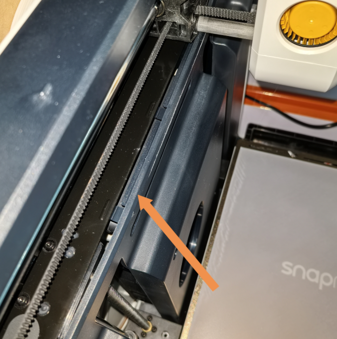
(1) As shown in the image below, during Y axis homing, the Y axis slider will collide with the front pillar. If there is debris on either side of the contact surface, such as leftover filament, it will cause an error. Please check that the contact area is clean.
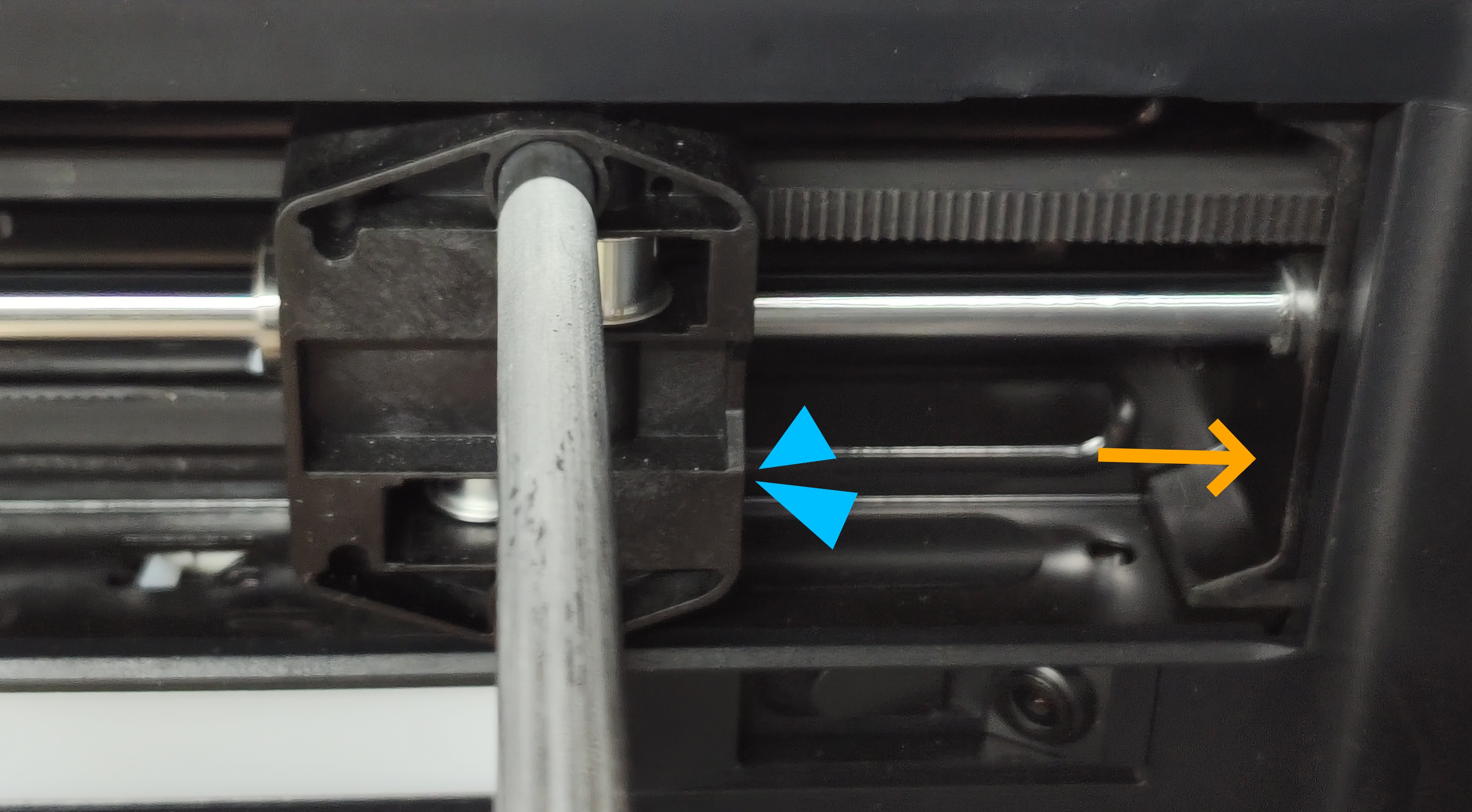
As shown in the image, there is filament sticking to the homing position, which can cause errors.
(2) As shown in the image below, during X axis homing, the toolhead swapper cover will collide with the Y axis slider. If there is debris on either side of the contact surface, such as leftover filament, it will cause an error. Please ensure the contact area is clean.
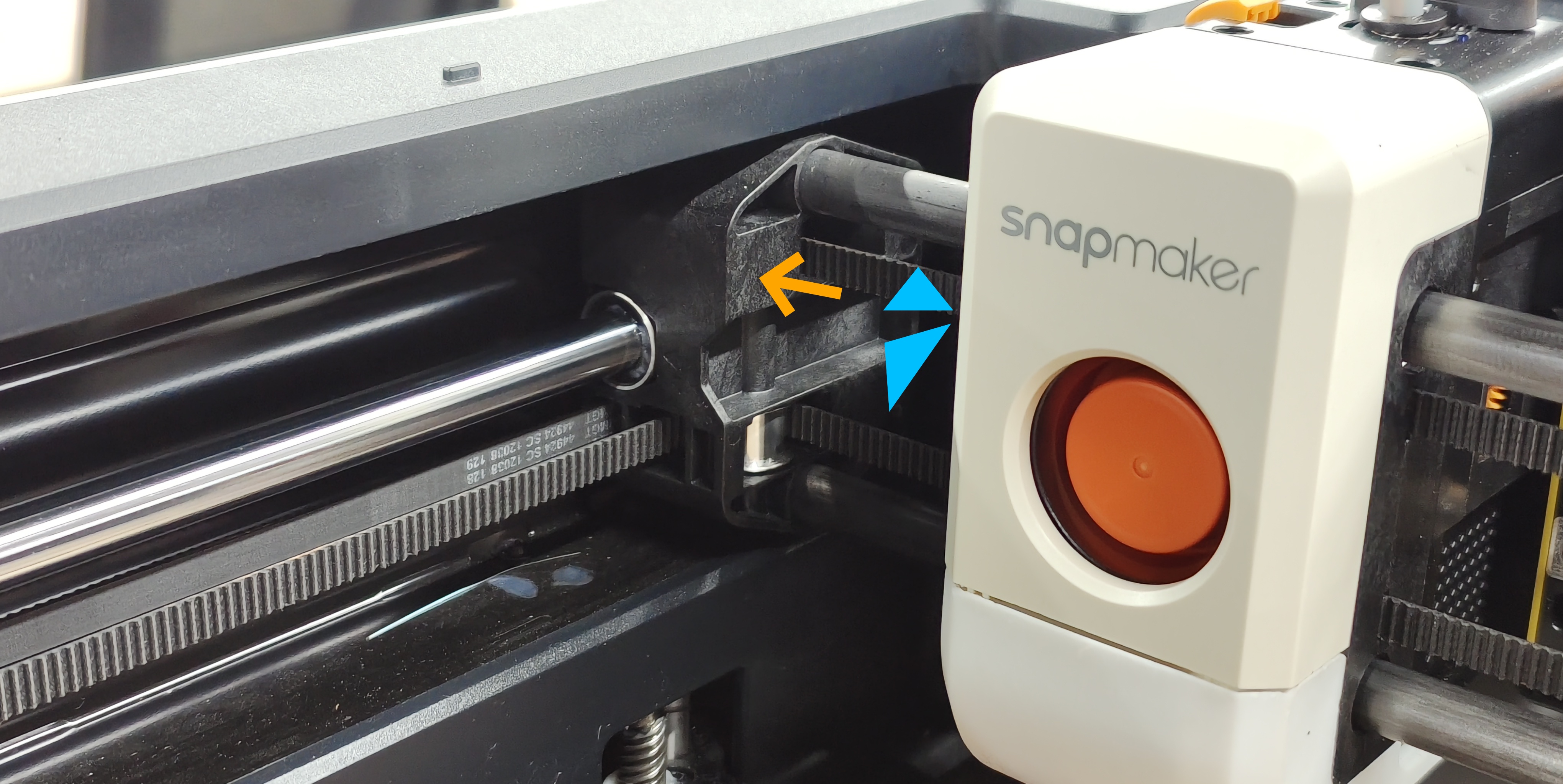
(3) In some cases (for example, when excessive force is applied during filament holder installation), the inner panel may be lifted. Check whether the inner panel has been lifted, as this may prevent the X-axis from homing properly.
¶ Step 2. Check if the toolheads are misplaced.
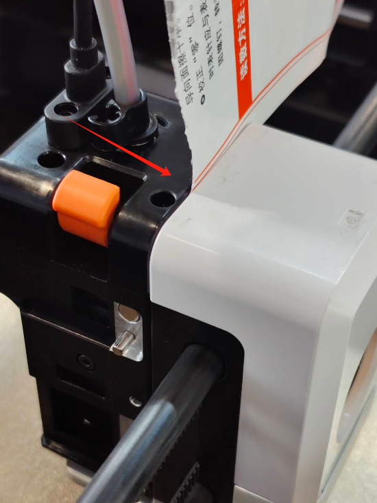
(1) If a toolhead is incorrectly placed in the docking bracket, for example, as shown in the image, toolhead 3 is placed in toolhead 4’s position, it can cause detection errors.
(2) Check if the toolhead is installed correctly. After installation, the red marker on the slider should no longer be visible.

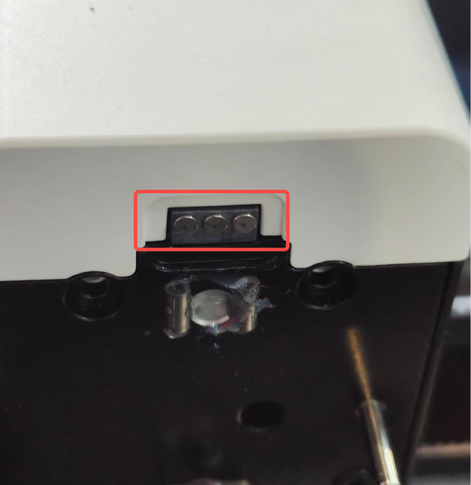
¶ Step 3. Clean pogo pin contacts
Before clicking 'Got it' to confirm the error and restart the print, please clean the pogo pin contacts with a dust-free cloth and alcohol. Make sure there is no dust or grease on the surface.
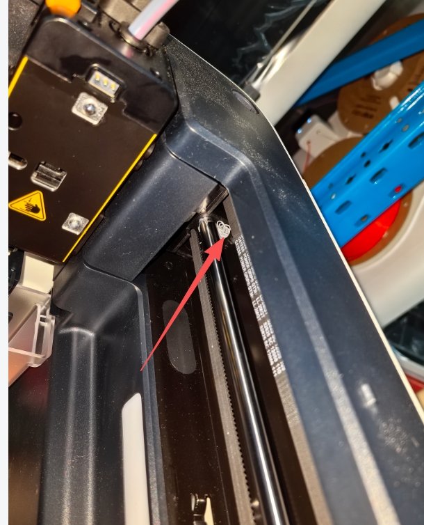
¶ Step 4. Check for housing interference
If the issue persists after cleaning, check whether the plastic housing is interfering with the contact. You can use a piece of white paper to test for gaps. Normally, when the solid pins on the print head mounted on the X-axis carbon rods are properly contacting the pogo pins on the other print head, the paper should not be able to pass through. If it does, it indicates poor contact between the two. If interference is found, adjust the cover screws accordingly.
¶ Step 5. Verify pogo pin spring tension
Check if the pogo pins still have proper spring tension.
Gently press the pogo pin using a dust-free cloth or glove, then release it to check whether the pin quickly returns to its original position.
¶ Step 6. Inspect solid pin wear
Inspect the solid pin on the carbon tube side for signs of wear. If there is noticeable wear, replace the corresponding part.
¶ Reach out to Snapmaker Support
After following the troubleshooting steps, if you find it difficult to resolve your issue, kindly submit a support ticket through https://snapmaker.formcrafts.com/u1-troubleshooting-request and share your troubleshooting results with some pictures/videos.
Our dedicated support team will be more than willing to assist you in resolving the issue.