¶ Overview
¶ Location
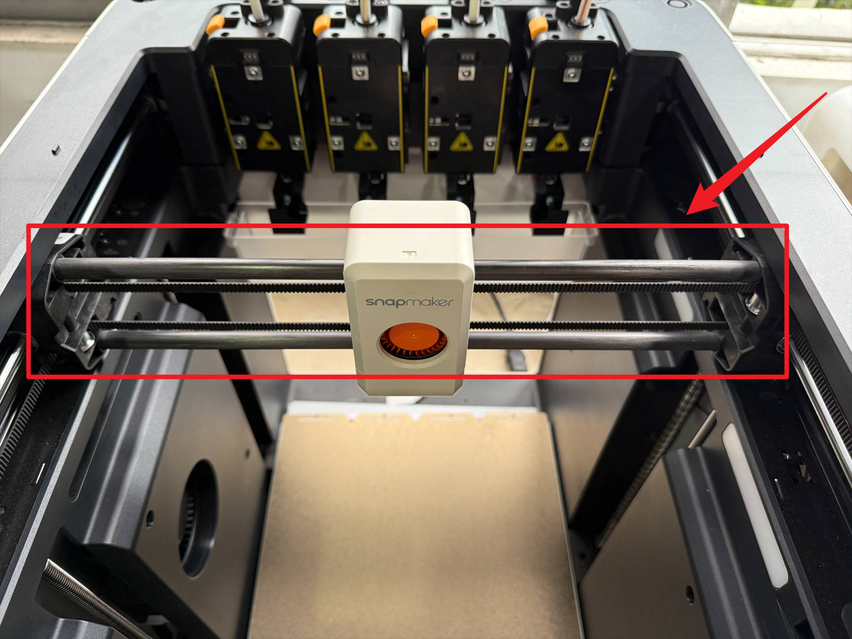
The X carbon rod assembly is located on the X-axis and is connected to the toolhead converter. Before replacing it, you need to remove the toolhead converter.
¶ Difficulty and Time Estimate
- Difficulty:★★★★★(difficult)
- Estimated Time:180mins
¶ Where to Buy
This accessory is expected to be available on the official Snapmaker online store soon. Please stay tuned.
¶ Tools and Parts Required
- H1.5 Hex key
- H2.0 Hex key
- Tweezers / Flathead screwdriver
- Strong needle-nose pliers
- Fine wire or Copper wire
- Zip tie
- New carbon rod
¶ Procedure
¶ Step 1. Unload filament
-
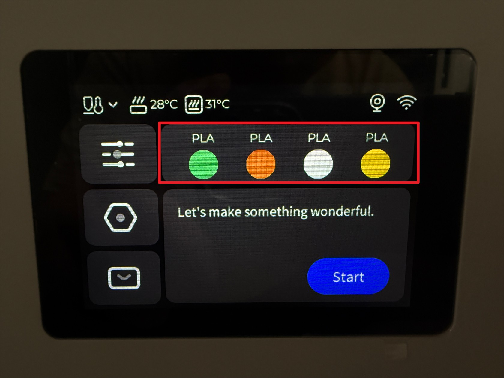
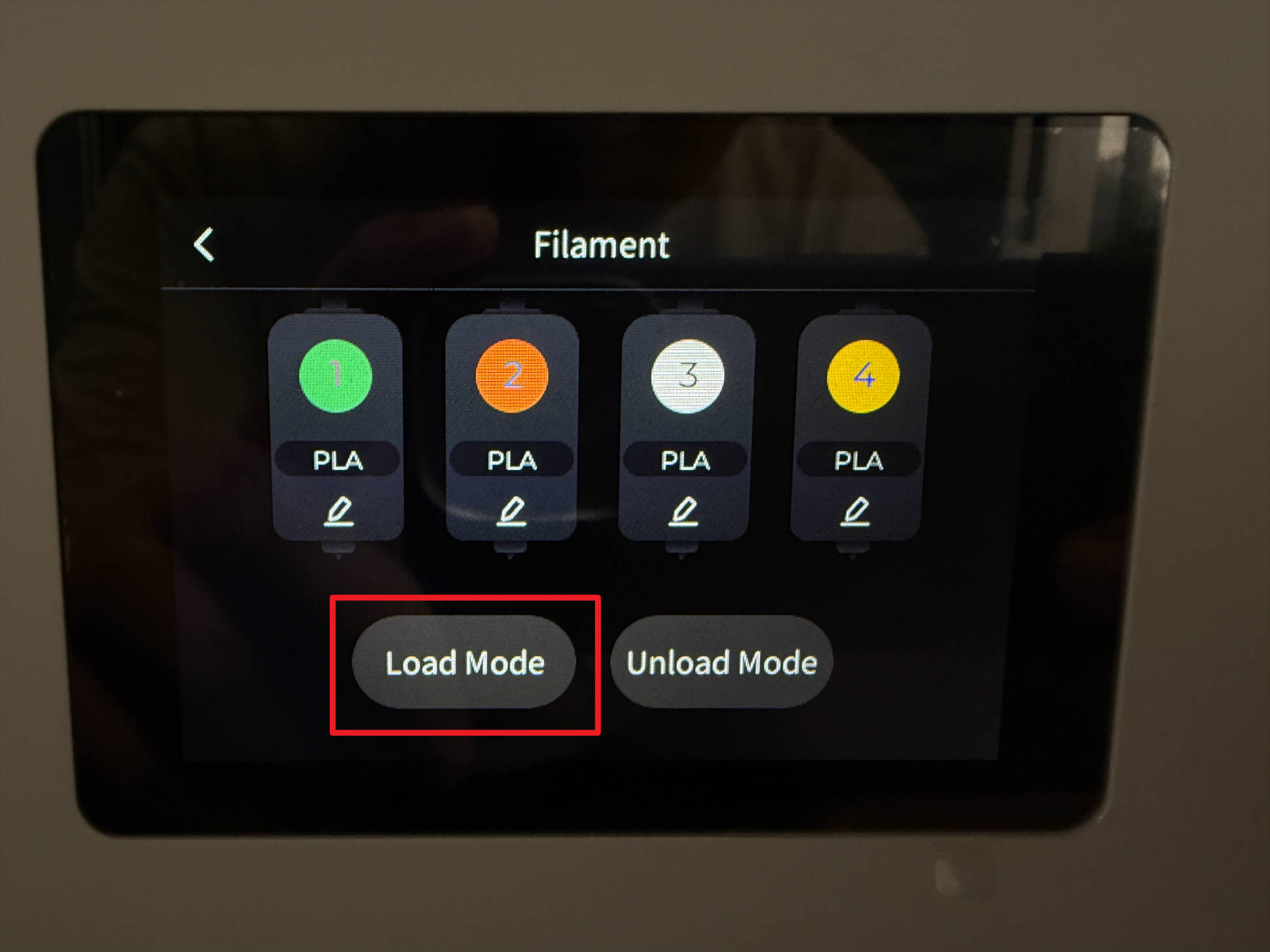
Tap the marked position on the screen
-
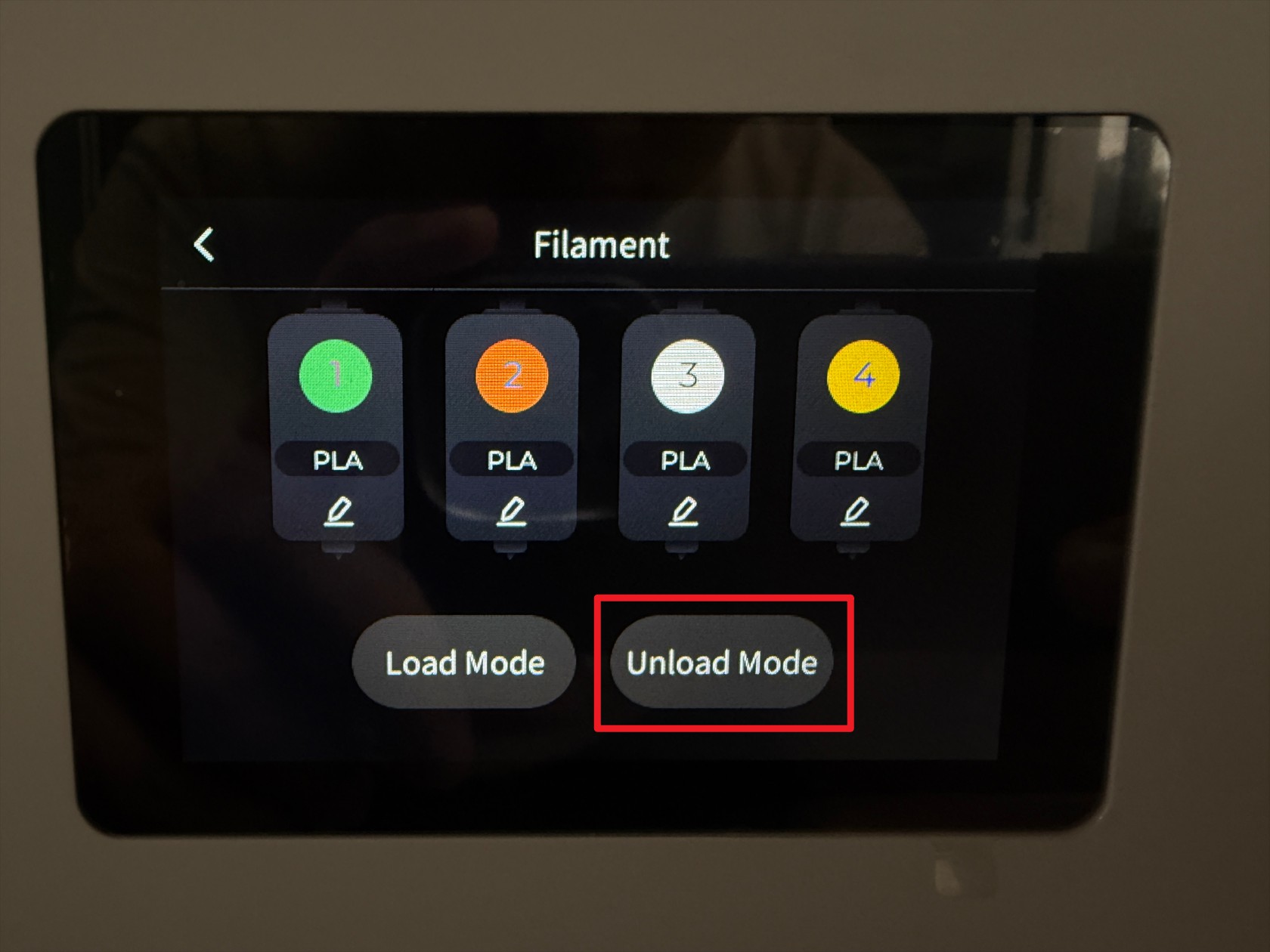
Tap Unload Mode
-
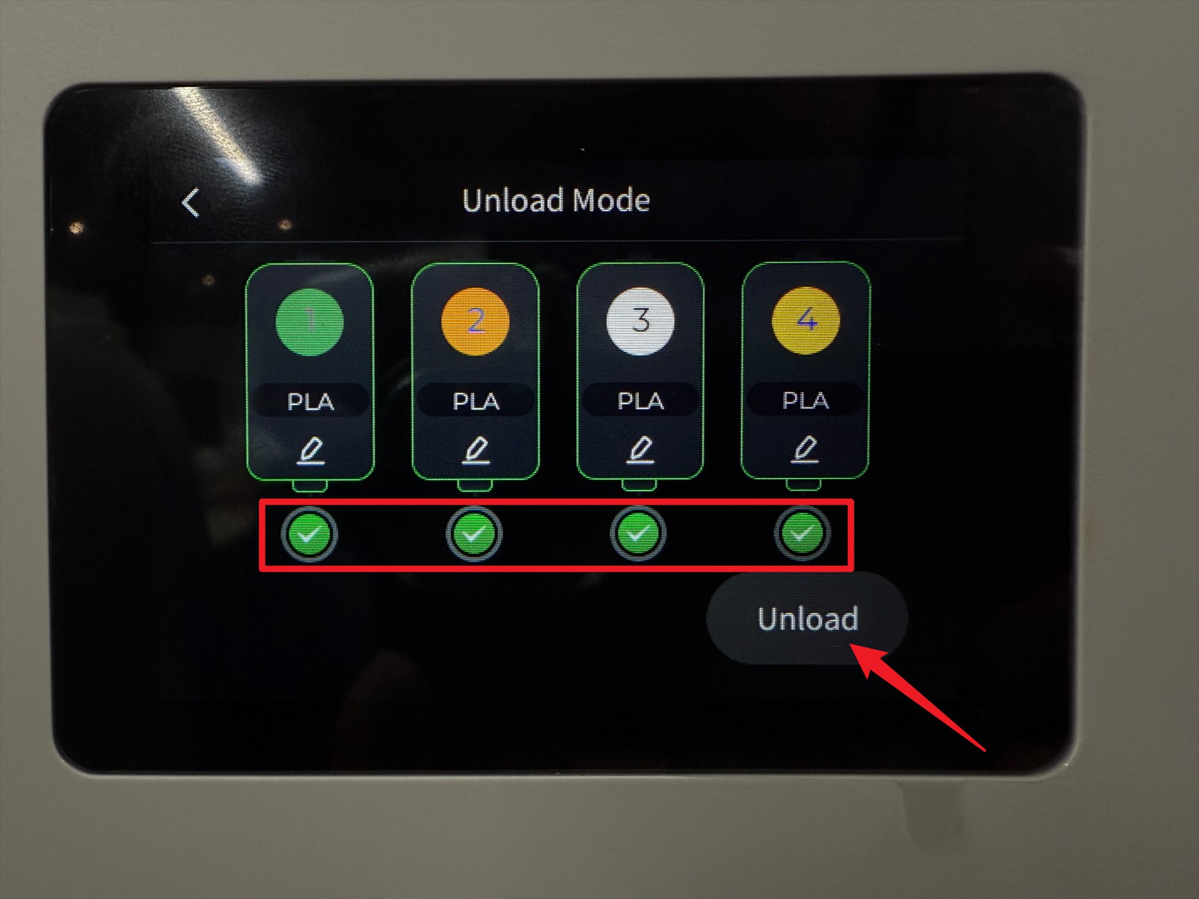
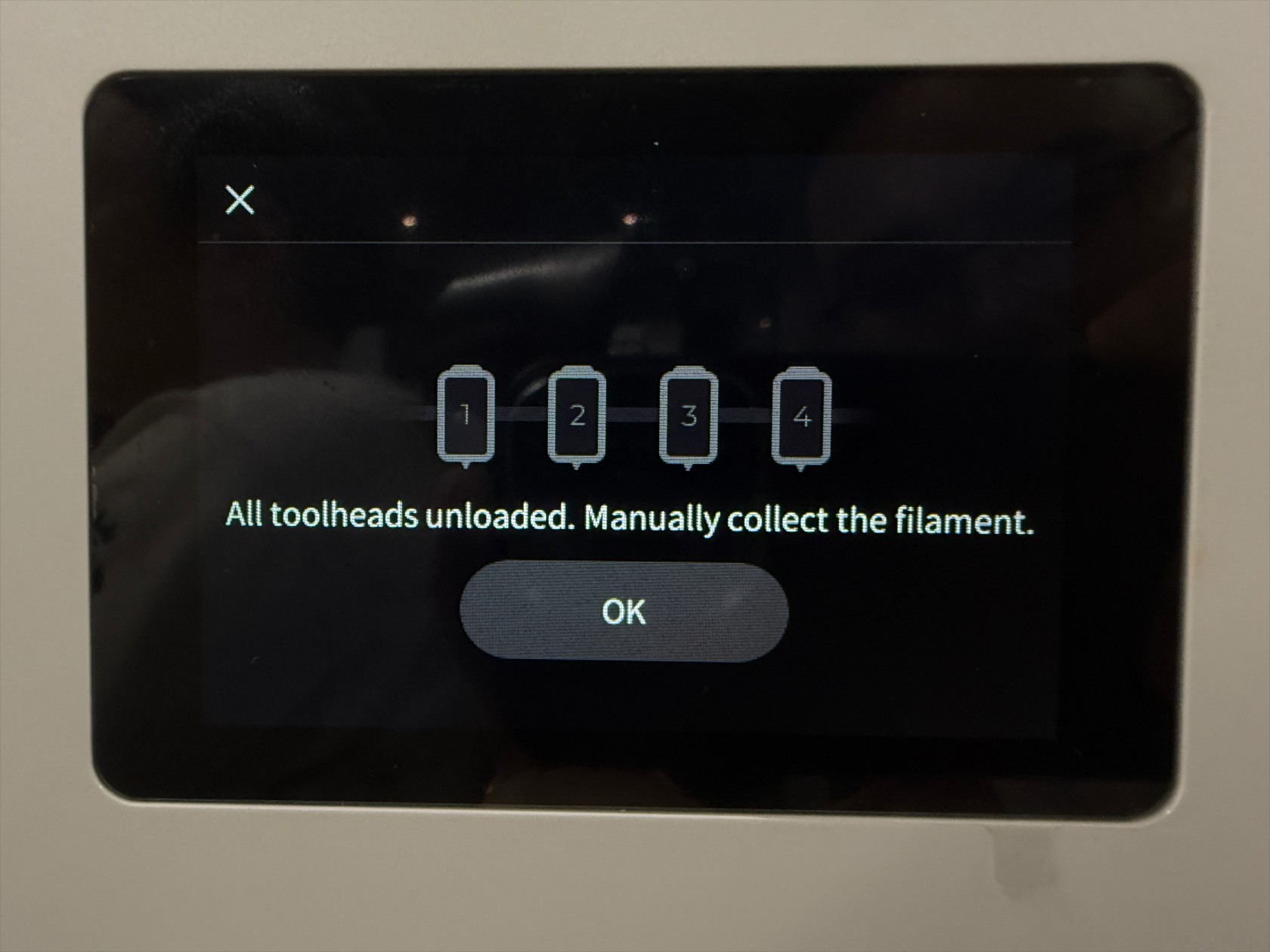
Select all toolheads and tap Unload
-
Wait for the printer to complete the filament unloading automatically
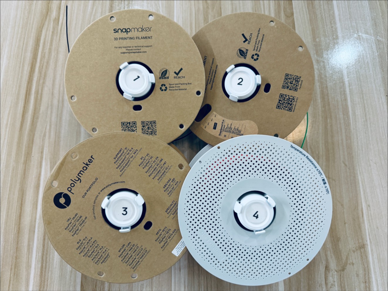
-
Rotate the spools to retract all filament, then remove the 4 spools (including the spool holders)

¶ Step 2. Remove the feeders on both sides
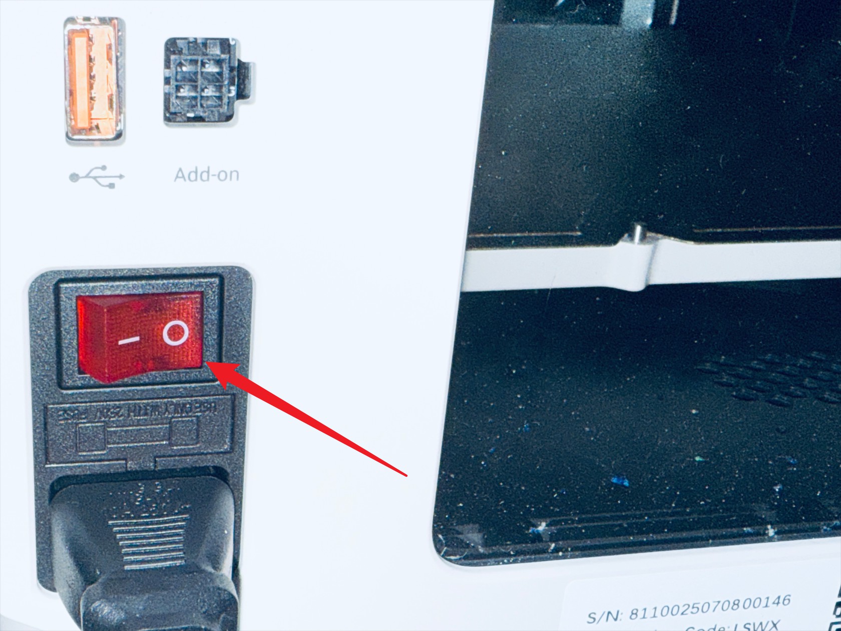
-
Power off the printer and disconnect the power supply
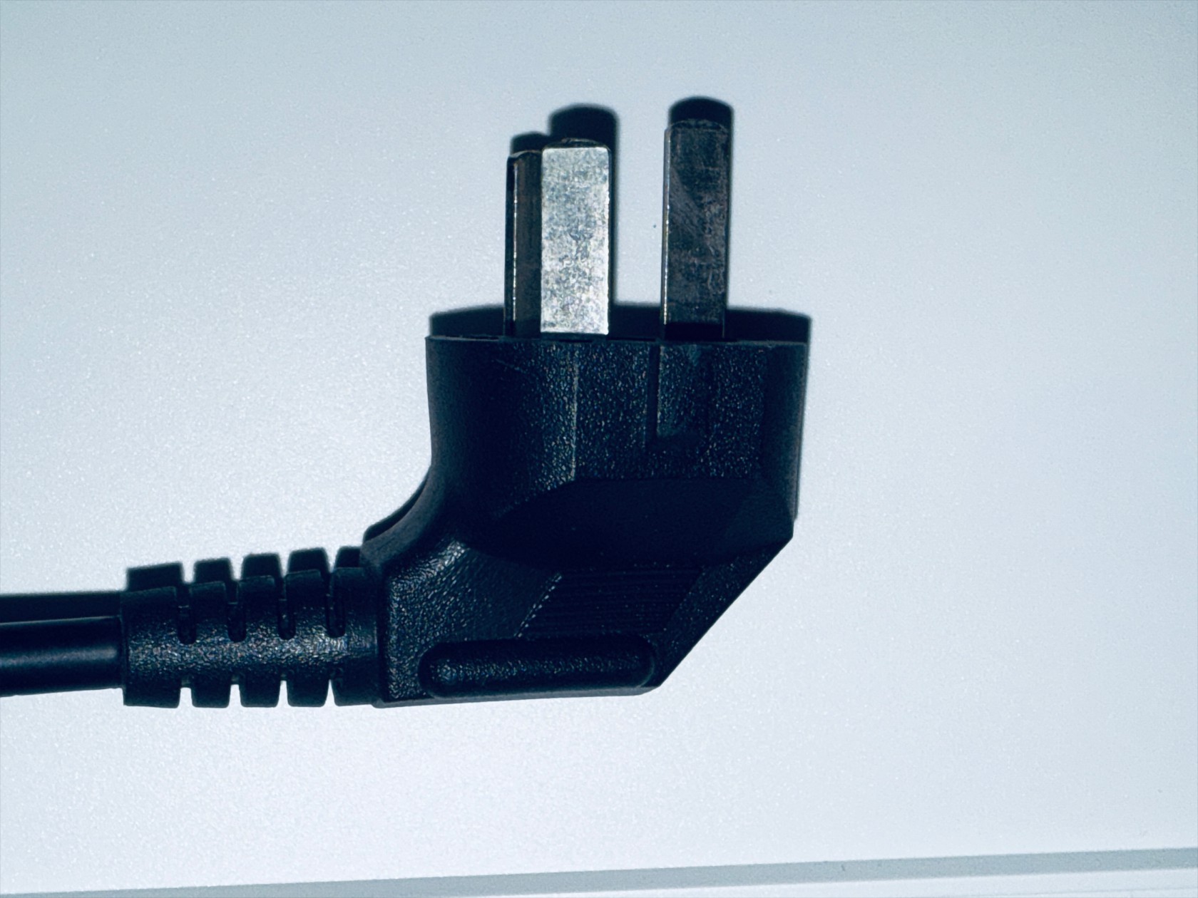
-
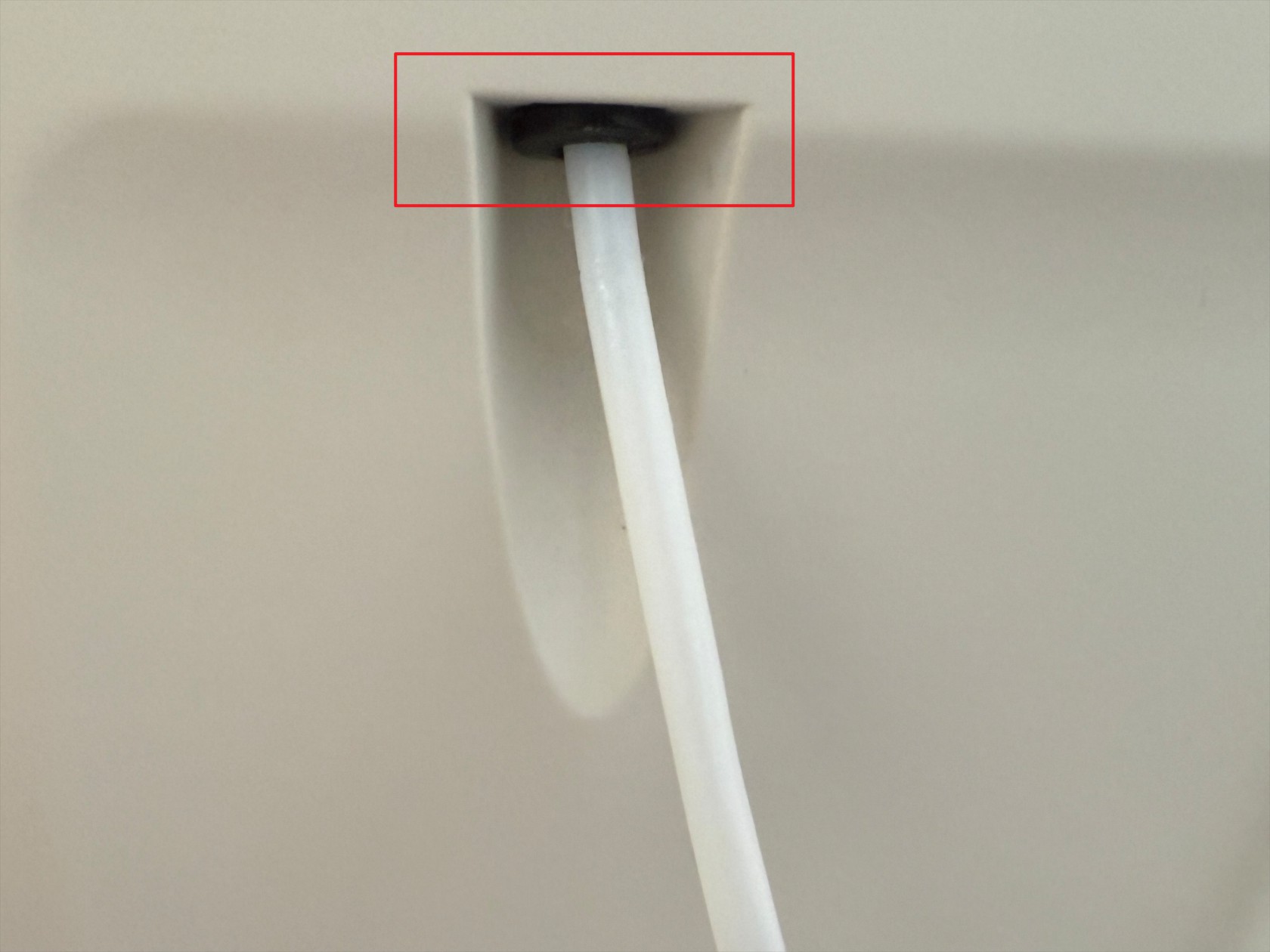
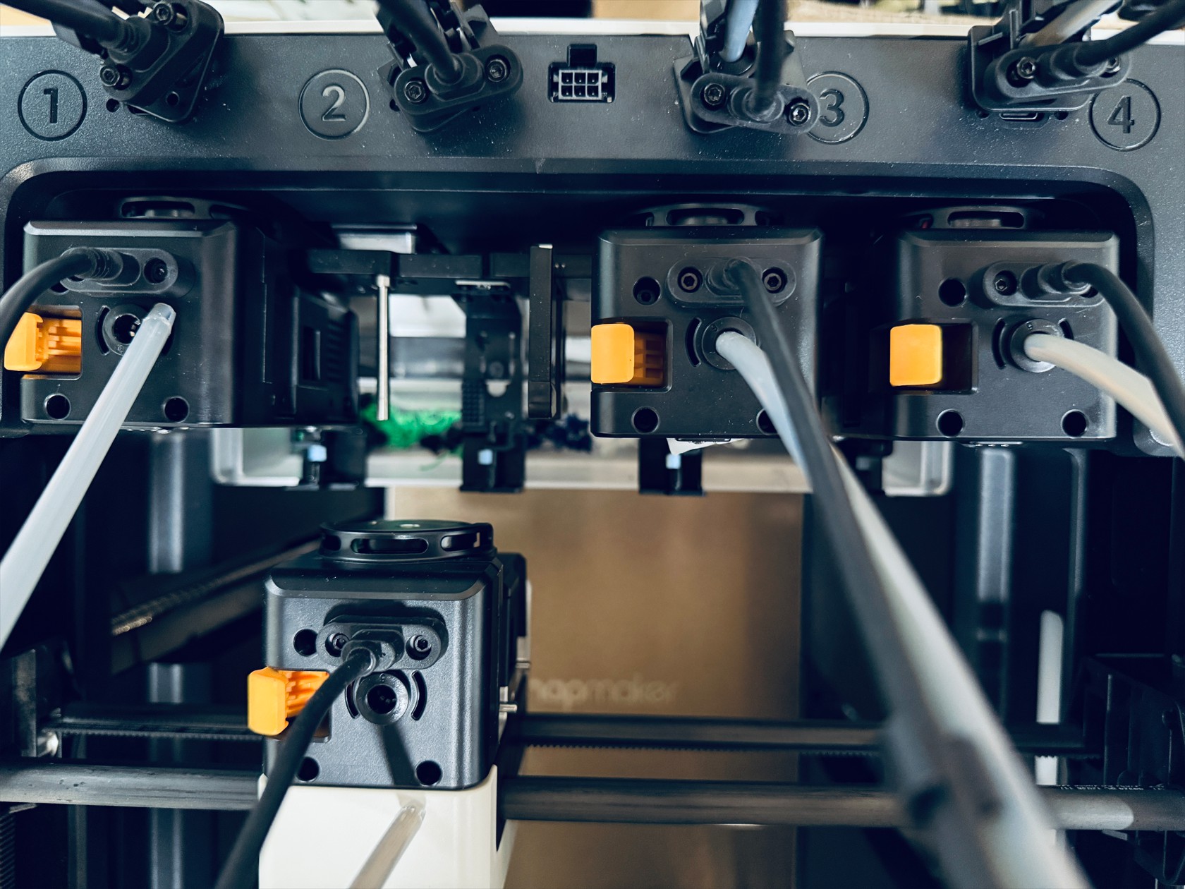
Press the quick connectors at the back of the machine and remove the 4mm filament tubes connected to the feeders. Repeat the same steps to remove the remaining 4mm filament tubes
-
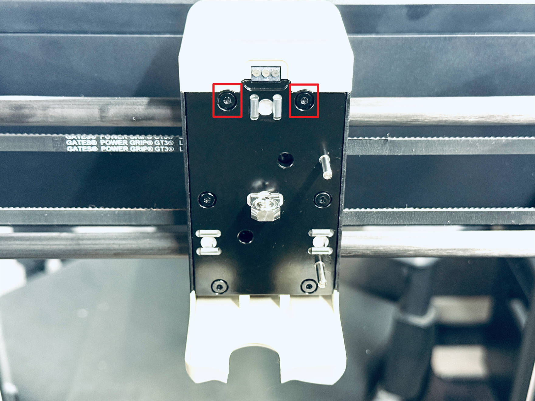
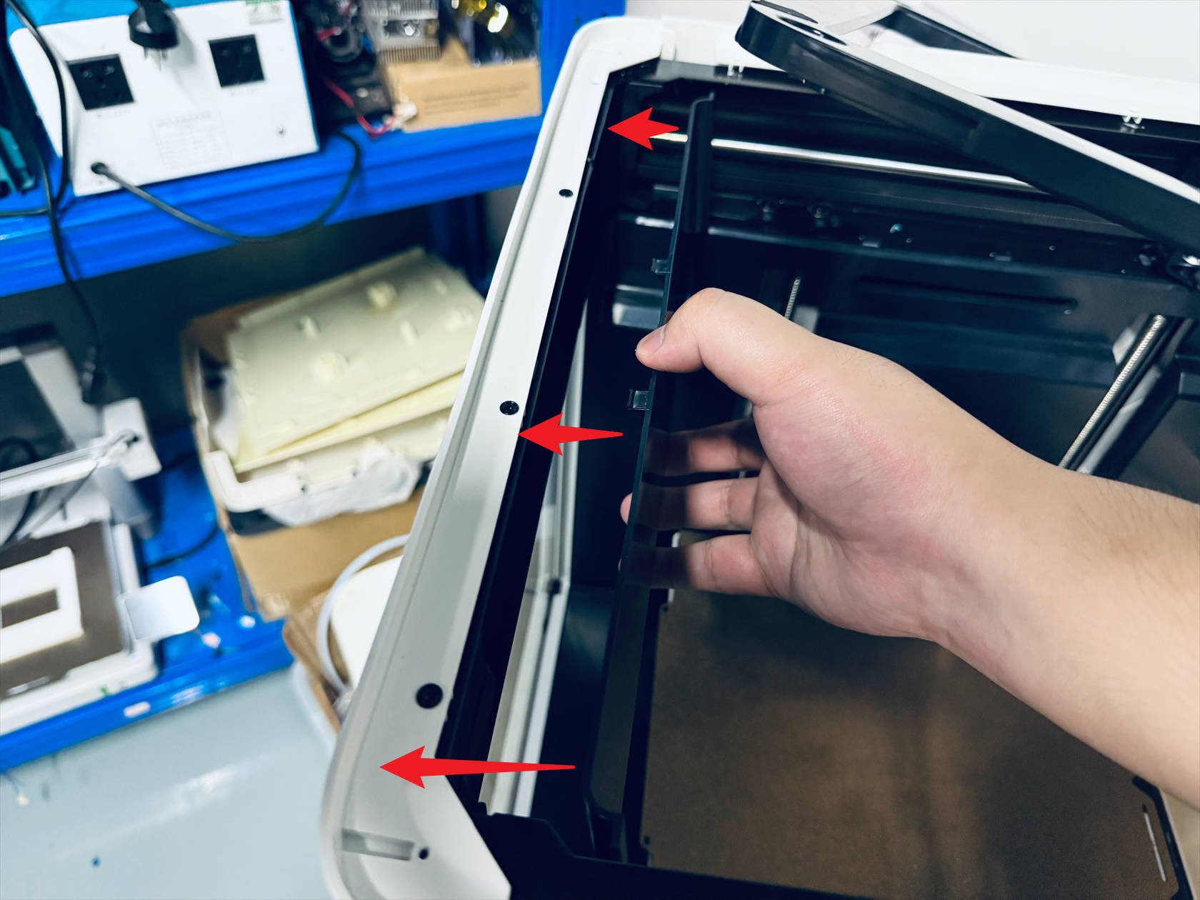
Remove the left feeder according to the instructions below
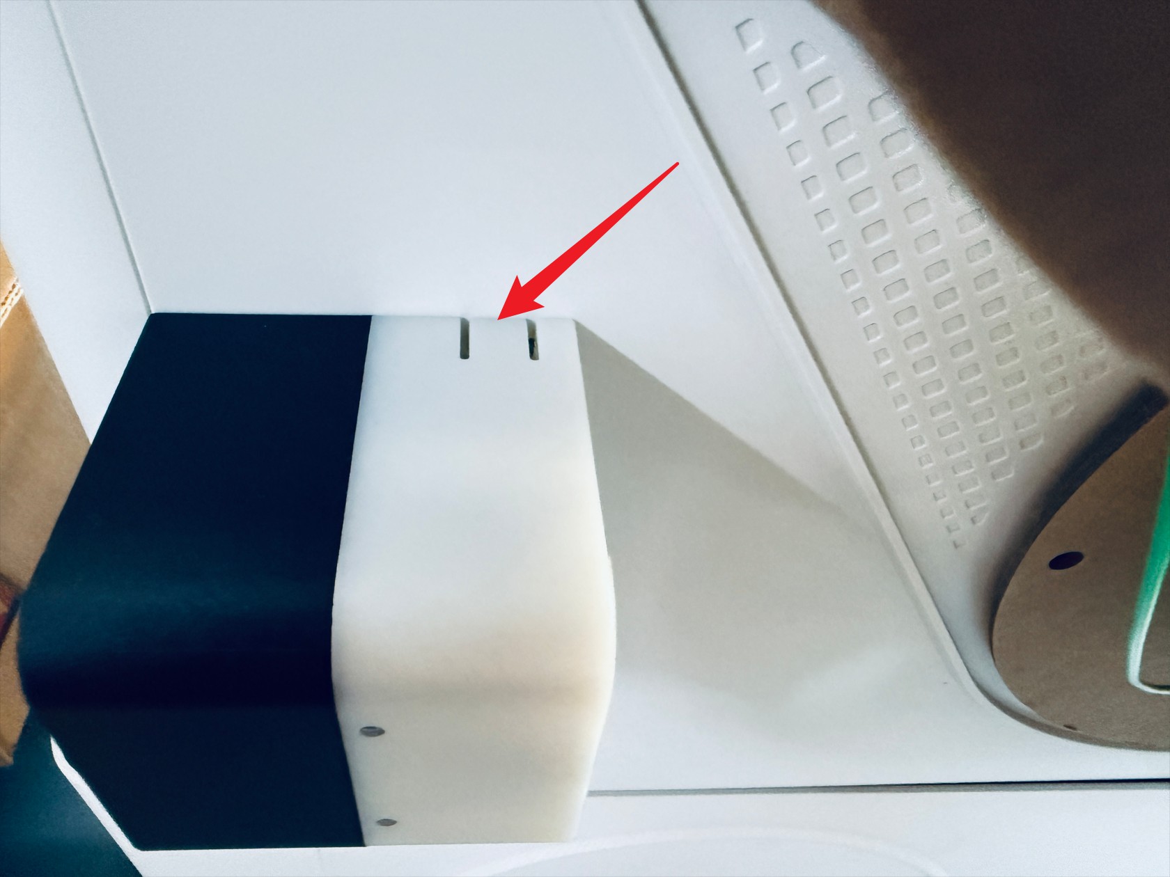 Press the marked position
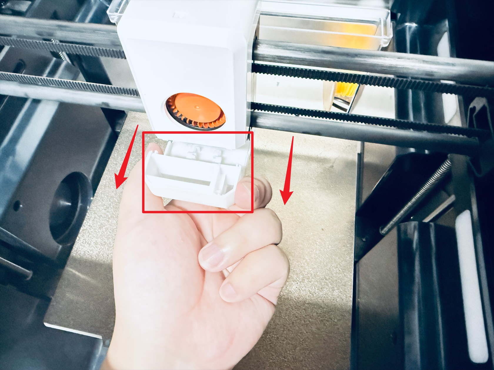
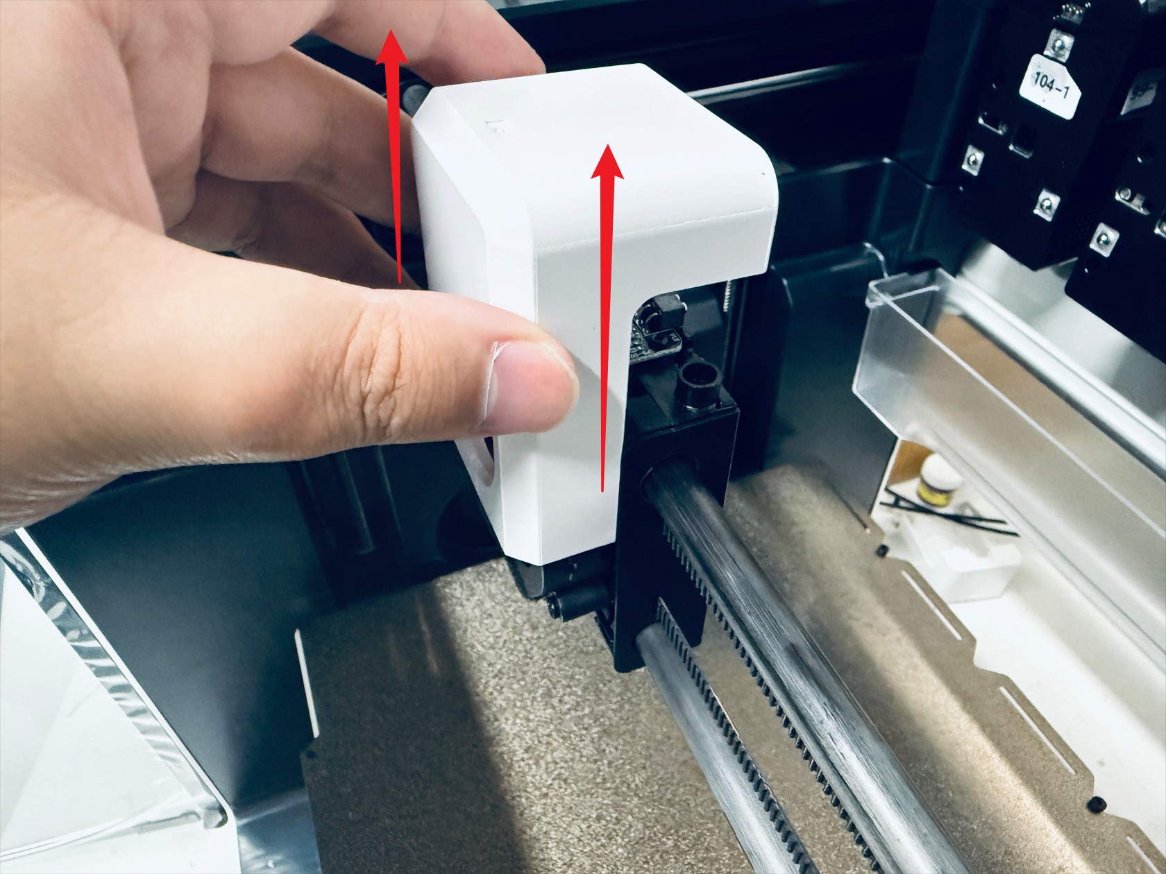
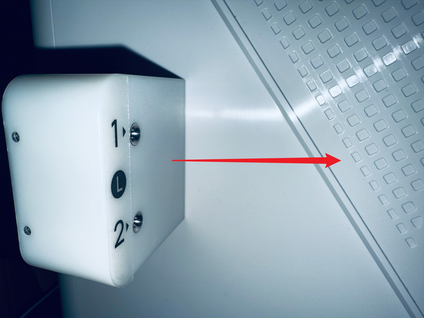 While holding down, move the feeder in the direction shown and remove it
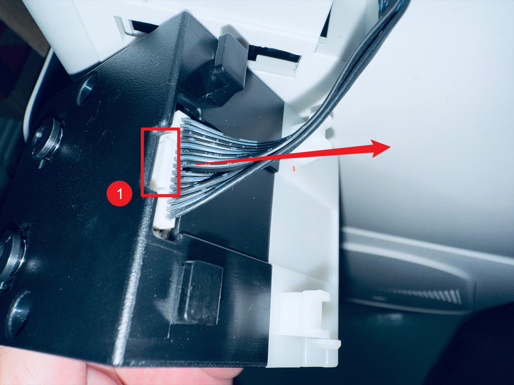 Press point 1 to disconnect the feeder cable
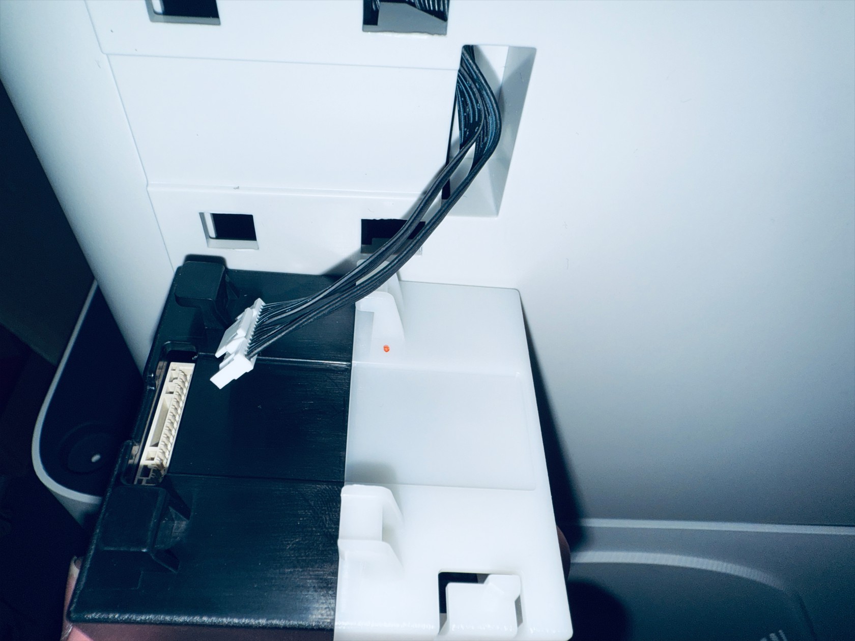 Complete
-
Remove the left feeder according to the instructions below
 Press the marked position
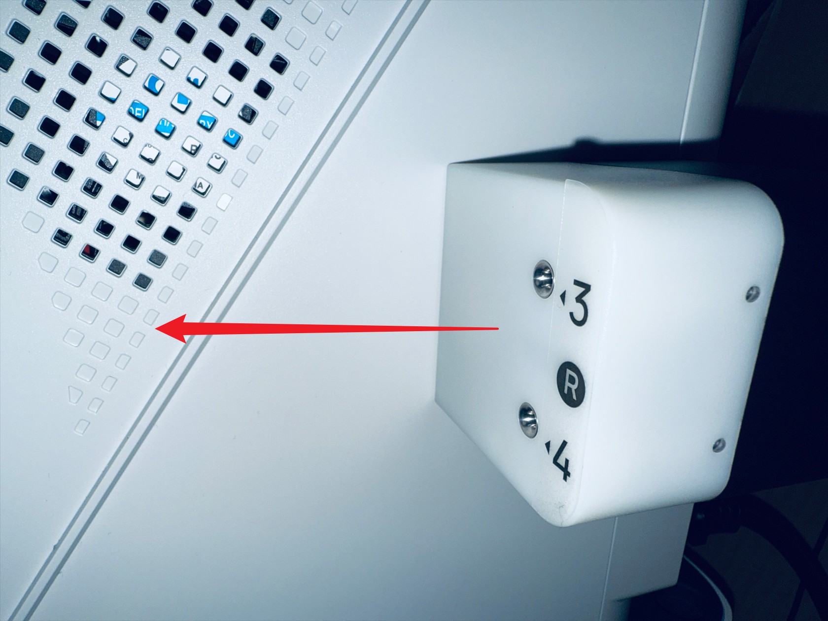 While holding down, move the feeder in the direction shown and remove it
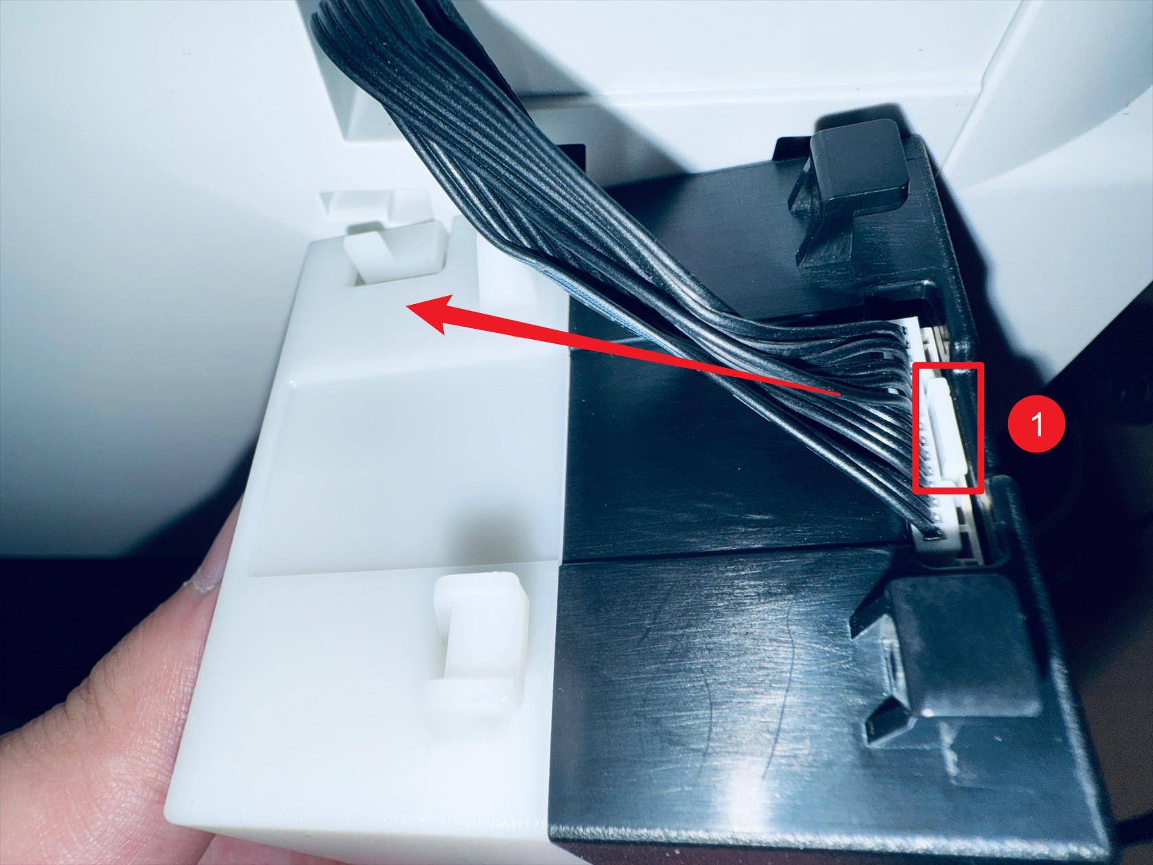 Press point 1 to disconnect the feeder cable
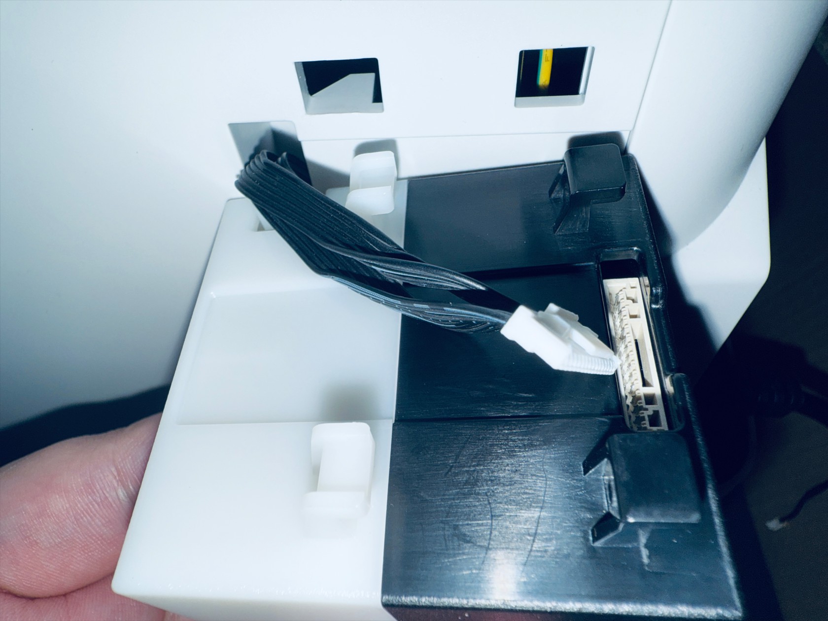 Complete
¶ Step 3. Remove the printer casing
-
Use an H2.0 hex key to unscrew the 8 screws securing the 4 USB cables, and unplug the USB cables

-
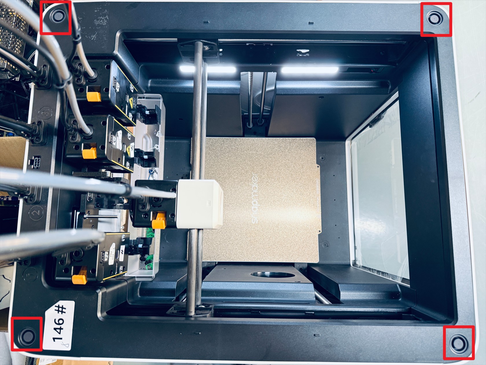
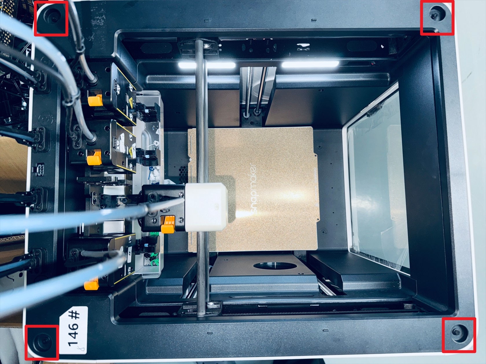
Remove the silicone plugs from the four corners of the top cover, then use an H2.0 hex key to unscrew the 4 screws beneath the silicone plugs
-
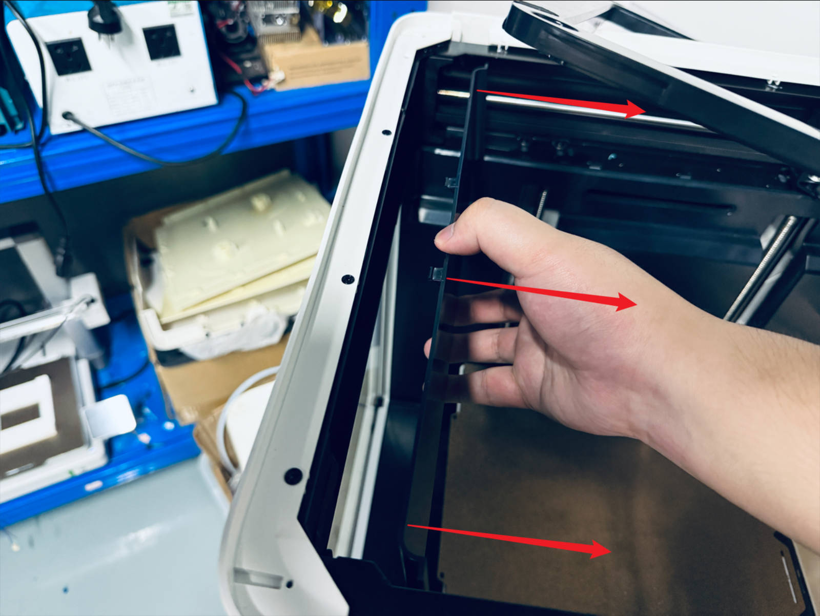
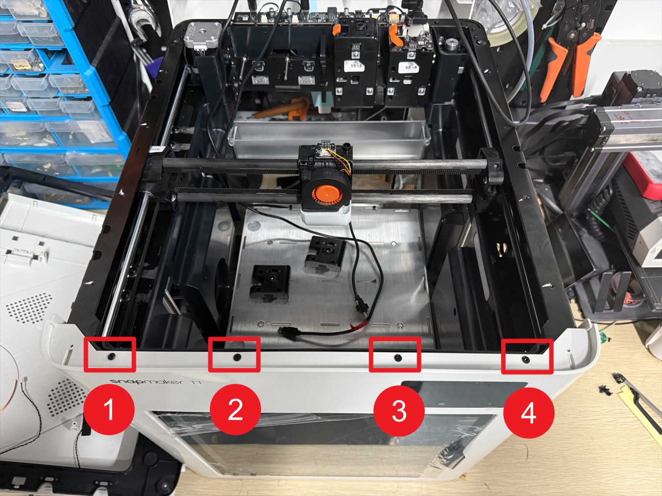
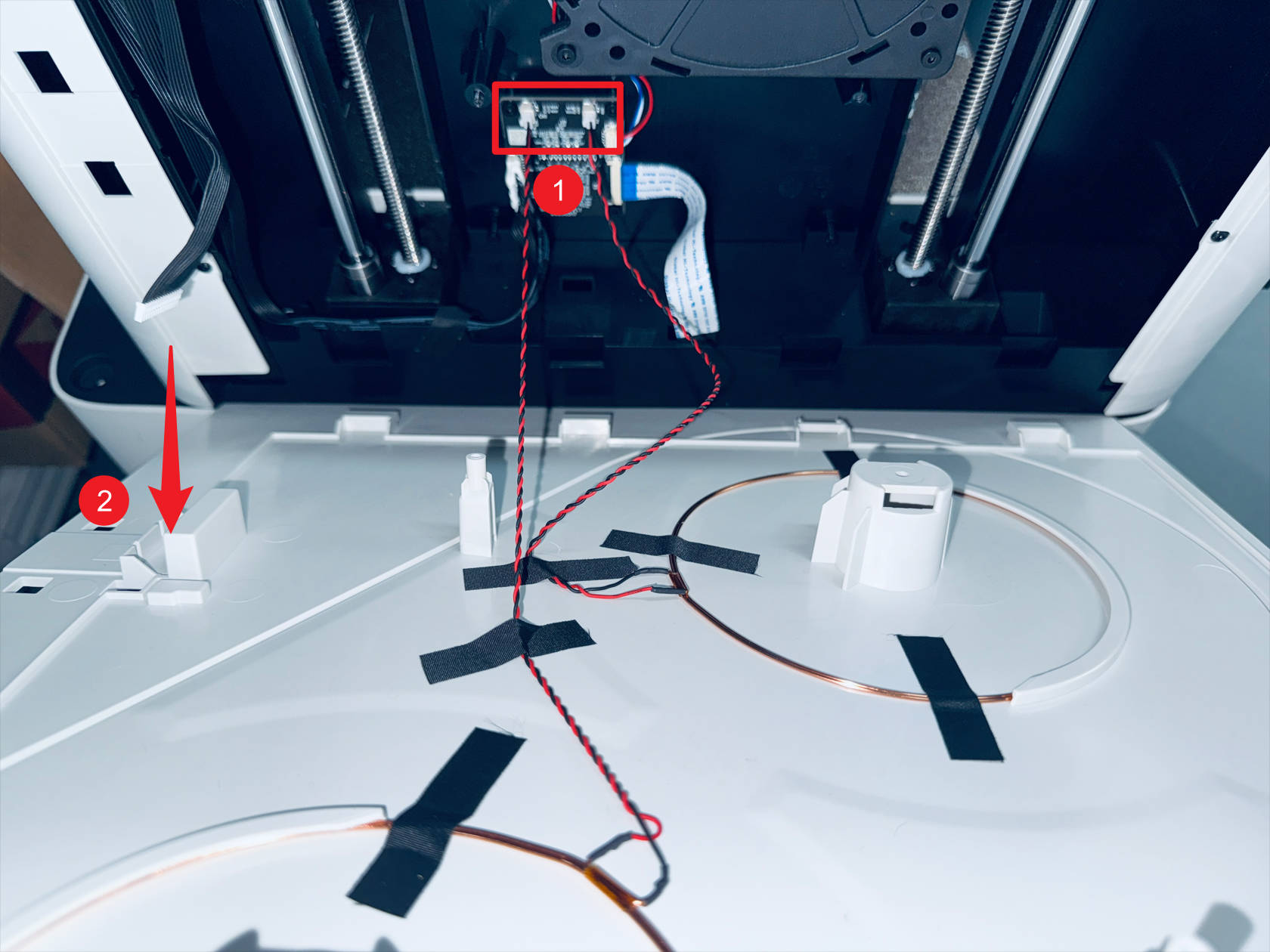
Remove the left plastic panel as follows:
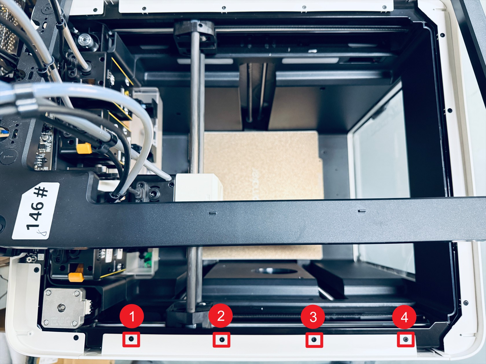 Misalign and move the top cover, then use an H2.0 hex key to unscrew screws 1–4
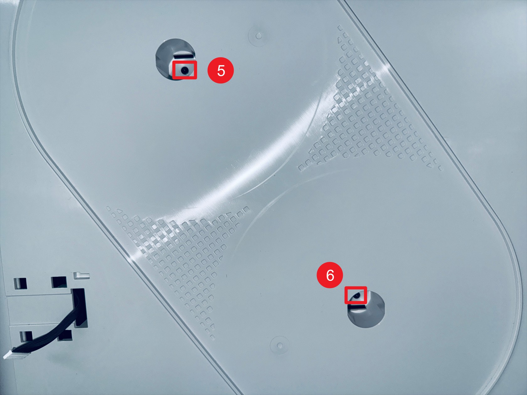 Use an H2.0 hex key to unscrew screws 5–6 (located in the holes corresponding to the spool holder)
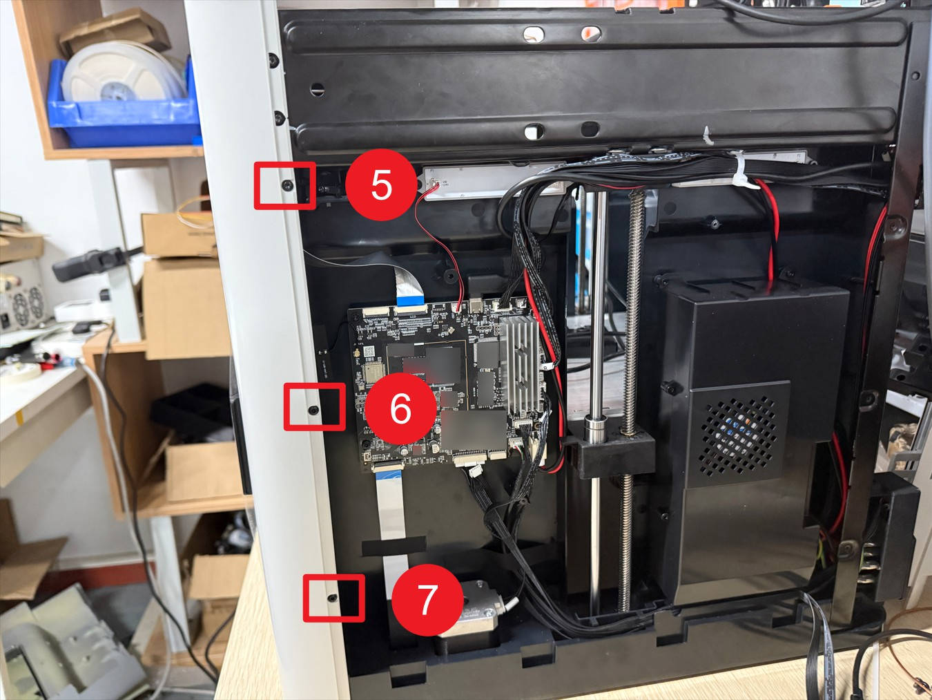
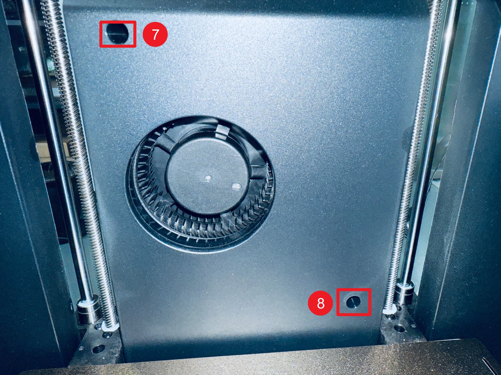 Use an H2.0 hex key to unscrew screws 7–8 (left inner panel)
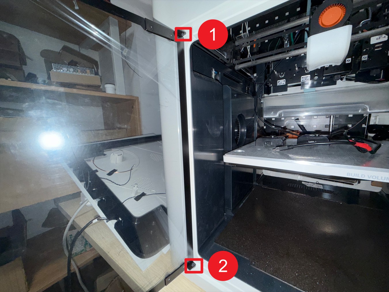
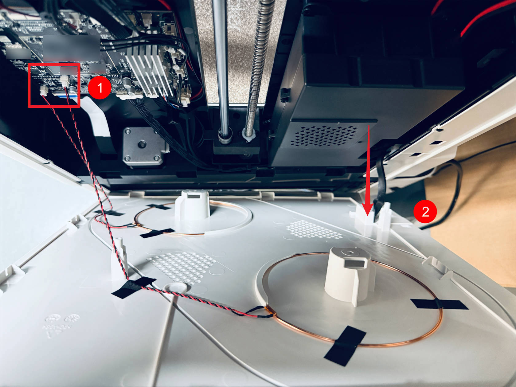
 The feeder cable passes through point 1
disconnect the 2 RFID cables at point 2, then remove the left plastic panel
-
Remove the right plastic panel as follows:
 Misalign and move the top cover, then use an H2.0 hex key to unscrew screws 1–4
 Use an H2.0 hex key to unscrew screws 5–6 (located in the holes corresponding to the spool holder)
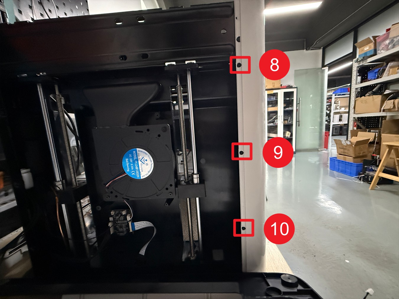
 Use an H2.0 hex key to unscrew screws 7–8 (right inner panel)
 The feeder cable passes through point 1
disconnect the 2 RFID cables at point 2, then remove the right plastic panel
-
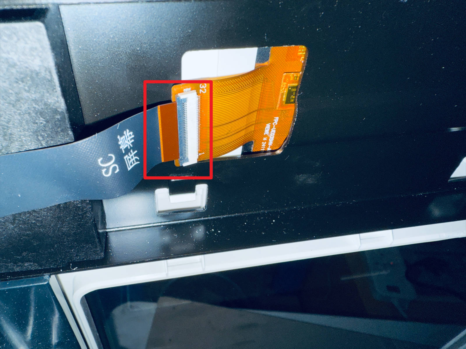
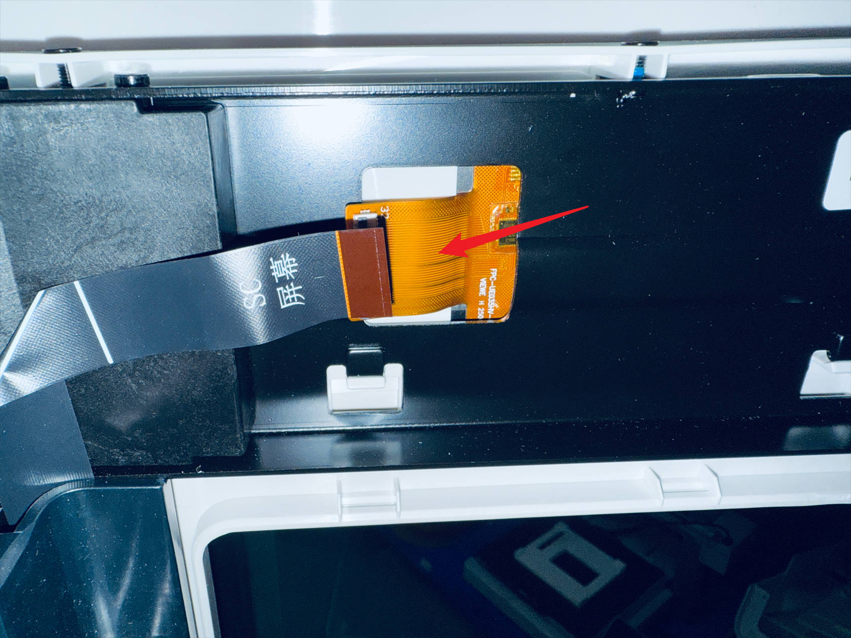
Remove the rear cover of the touchscreen and disconnect the FFC cable
-
Use an H2.0 hex key to unscrew a total of 10 screws securing the front panel and 2 screws on the glass door hinge, then remove the glass door hinge and the front panel.
¶ Step 4. Remove the toolhead swapper
-
Use an H2.0 hex key to unscrew 2 screws and remove the part cooling fan air duct and part cooling fan shroud
-
Disconnect the part cooling fan cable then use an H2.0 hex key to unscrew 2 screws and remove the part cooling fan

-
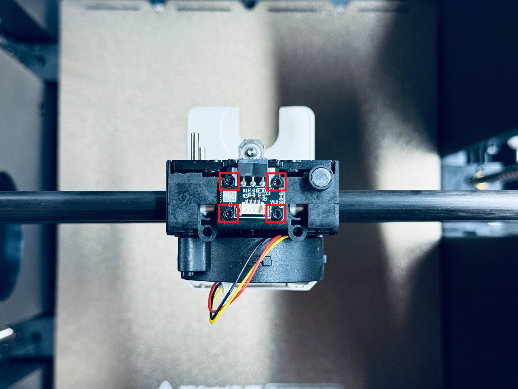
Use an H1.5 hex key to unscrew 4 screws and remove the part cooling fan adapter board
-
Use an H2.0 hex key to unscrew 4 screws and remove the toolhead swapper base
-
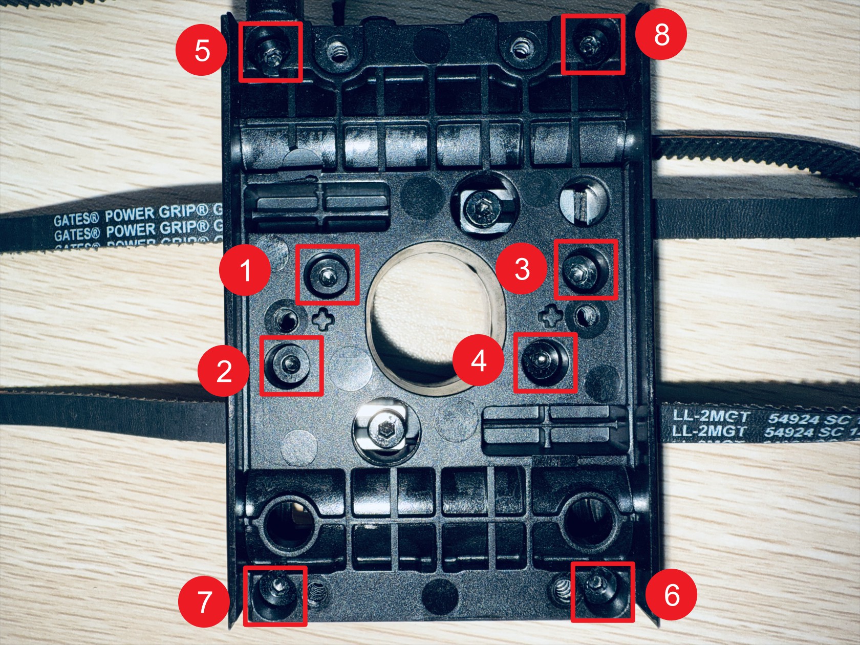
Use an H2.0 hex key to sequentially unscrew 8 screws and separate X-axis slider-1 and X-axis slider-2, note that X-axis slider-2 has 4 anti-backlash springs, after disassembling the X-axis sliders, place them safely to avoid loss
-
Use an H2.0 hex key to unscrew 2 screws securing the end tensioning movable block, note these 2 screws have lock nuts on the back of the slider, remove and store them safely
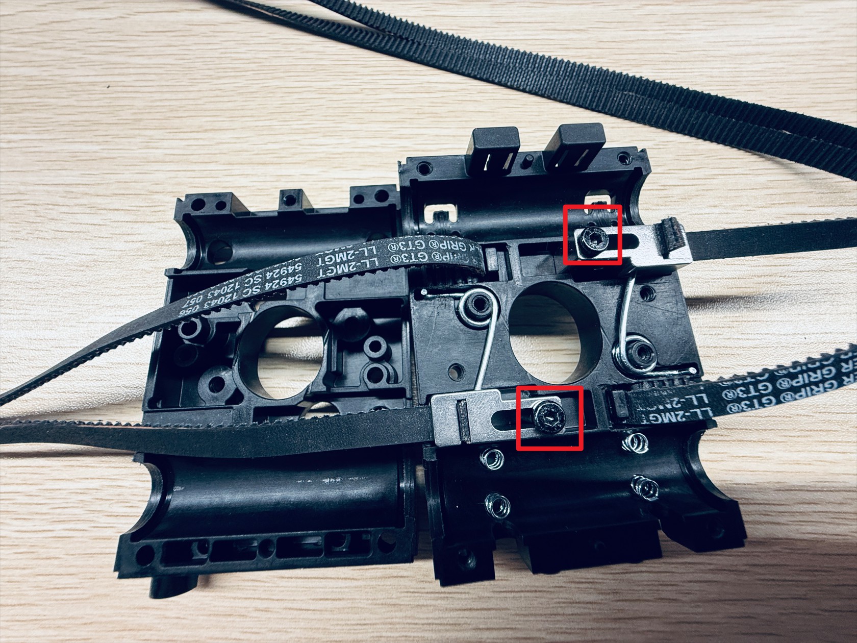
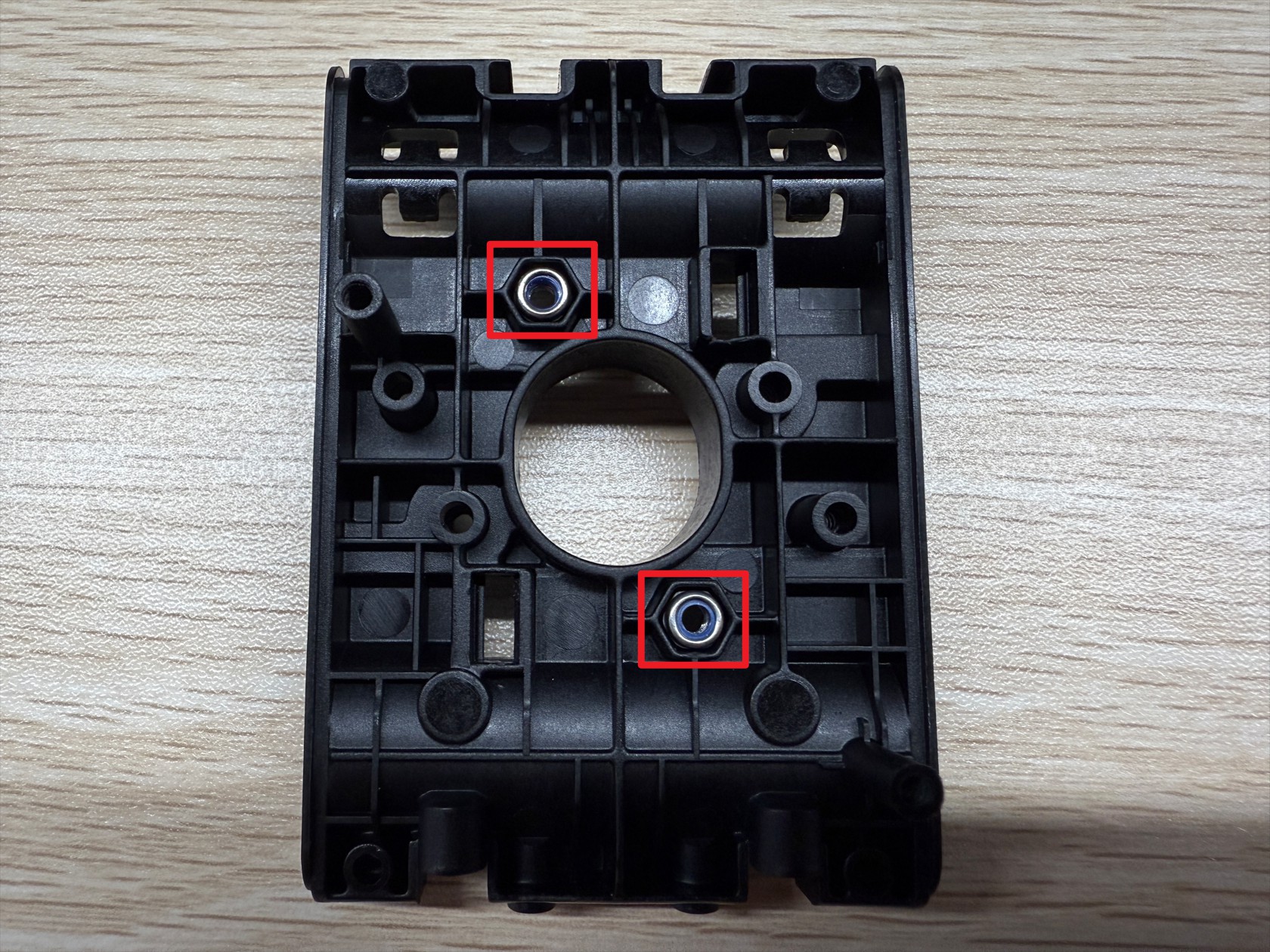
-
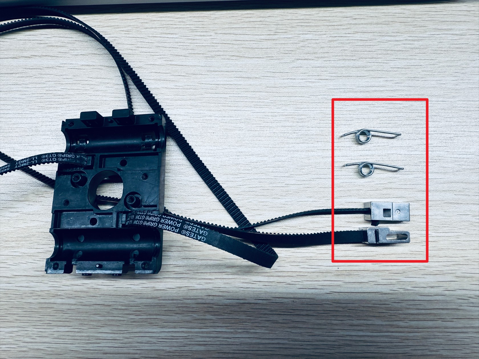
Slowly remove the end tensioning movable block and torsion springs, 2 each.
-
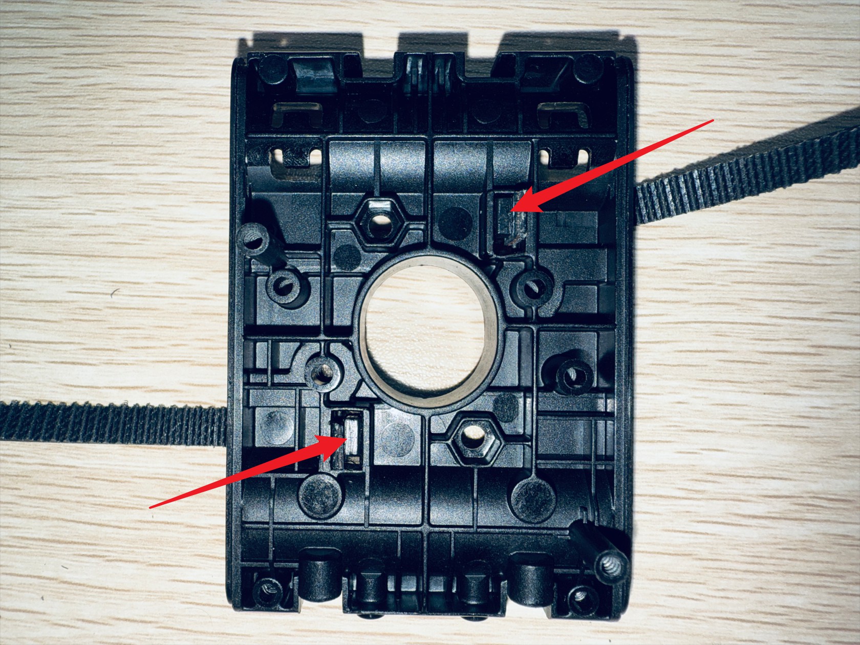
On the outer surface of X-axis slider-2, use an H2.0 hex key to push out the timing belt fixing block and remove the end of the timing belts fixed here
¶ Step 5. Replace the carbon rod
-
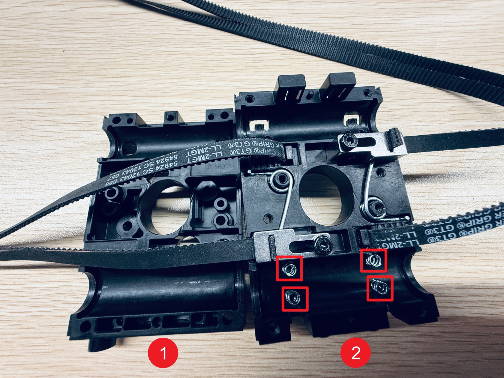
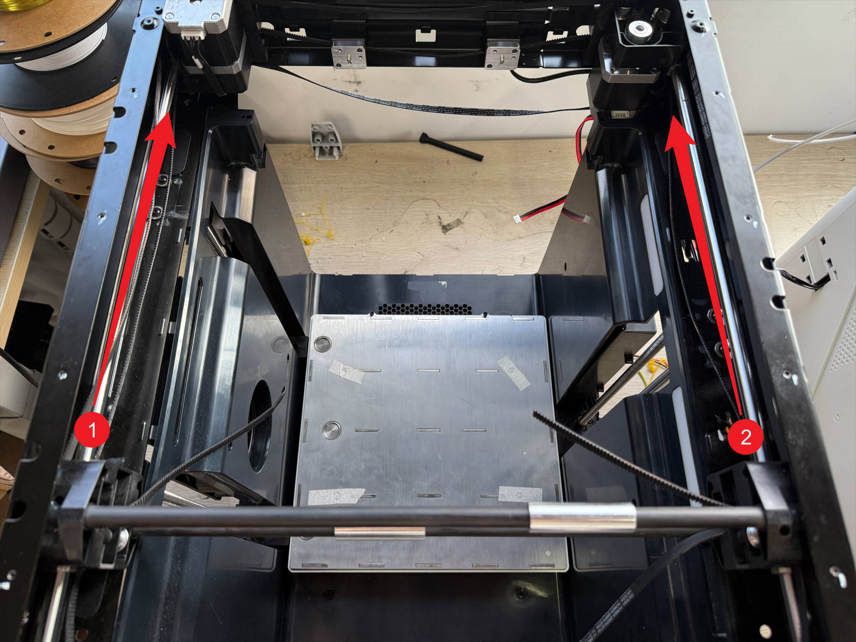
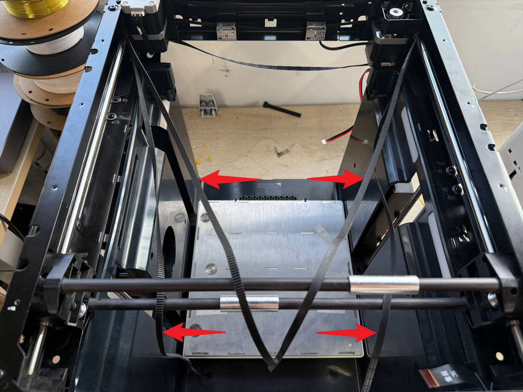
The XY timing belts are divided into upper and lower belts, remove both ends of each belt simultaneously from points 1 and 2
Note not to completely remove the timing belt from the frame
-
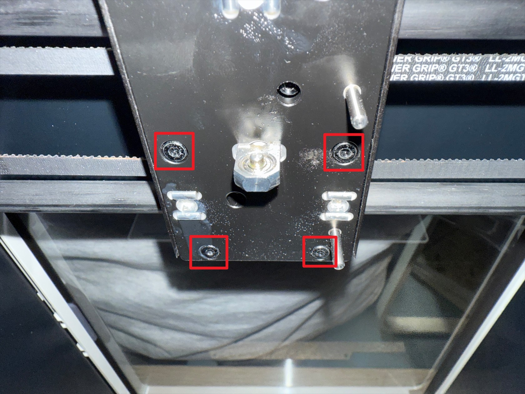
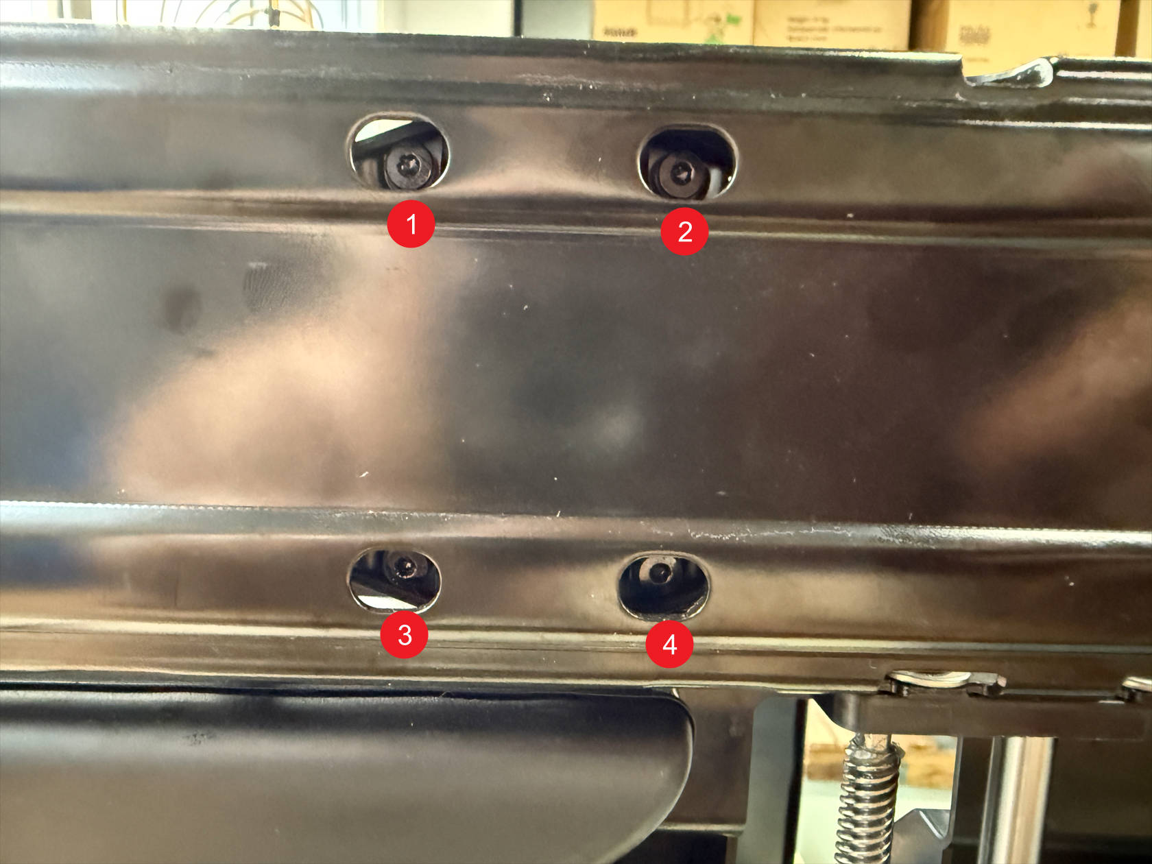
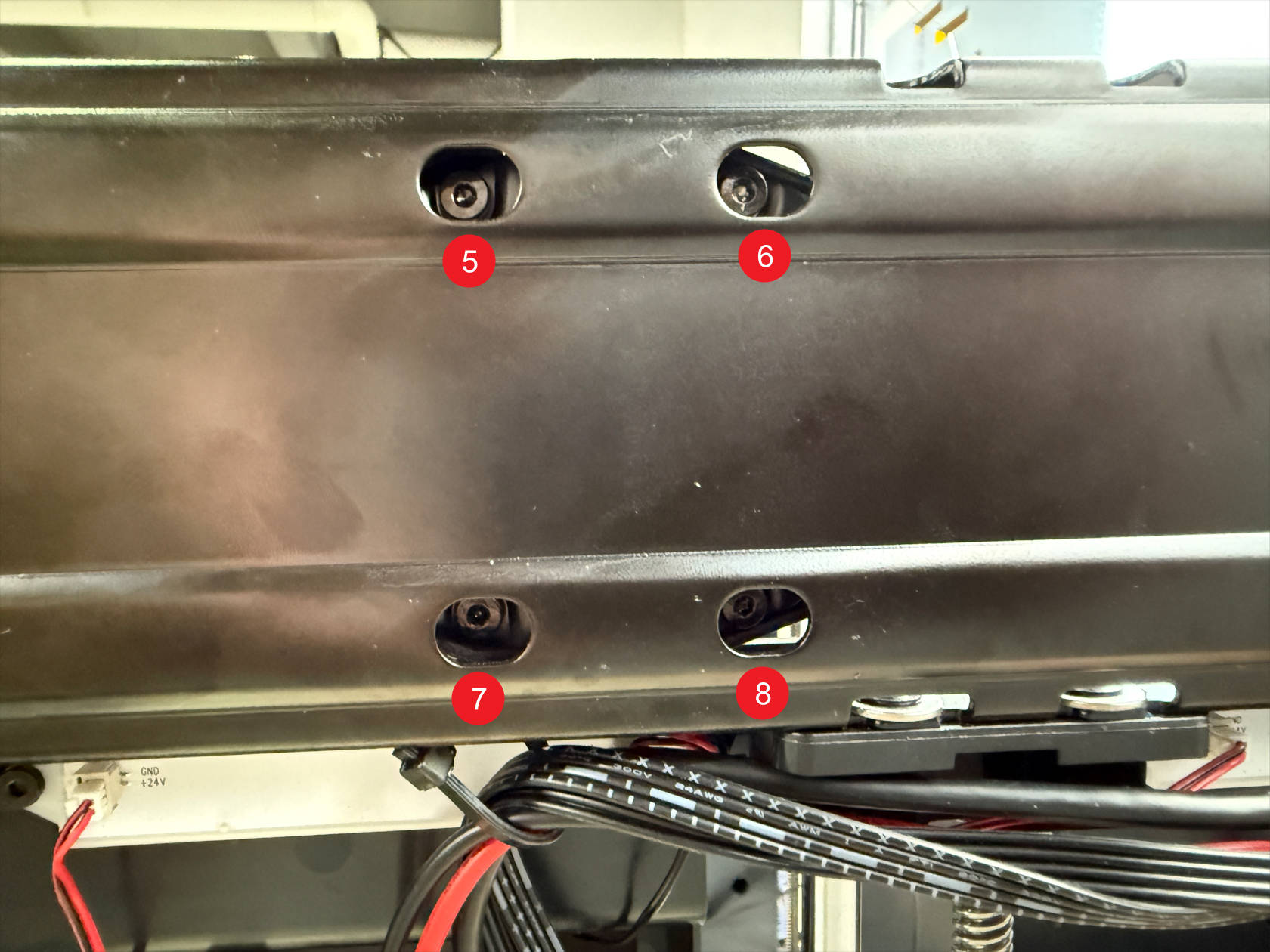
The machine side frames have holes for removing their securing screws
Slightly adjust the carbon rod position, use an H2.0 hex key to unscrew a total of 8 screws
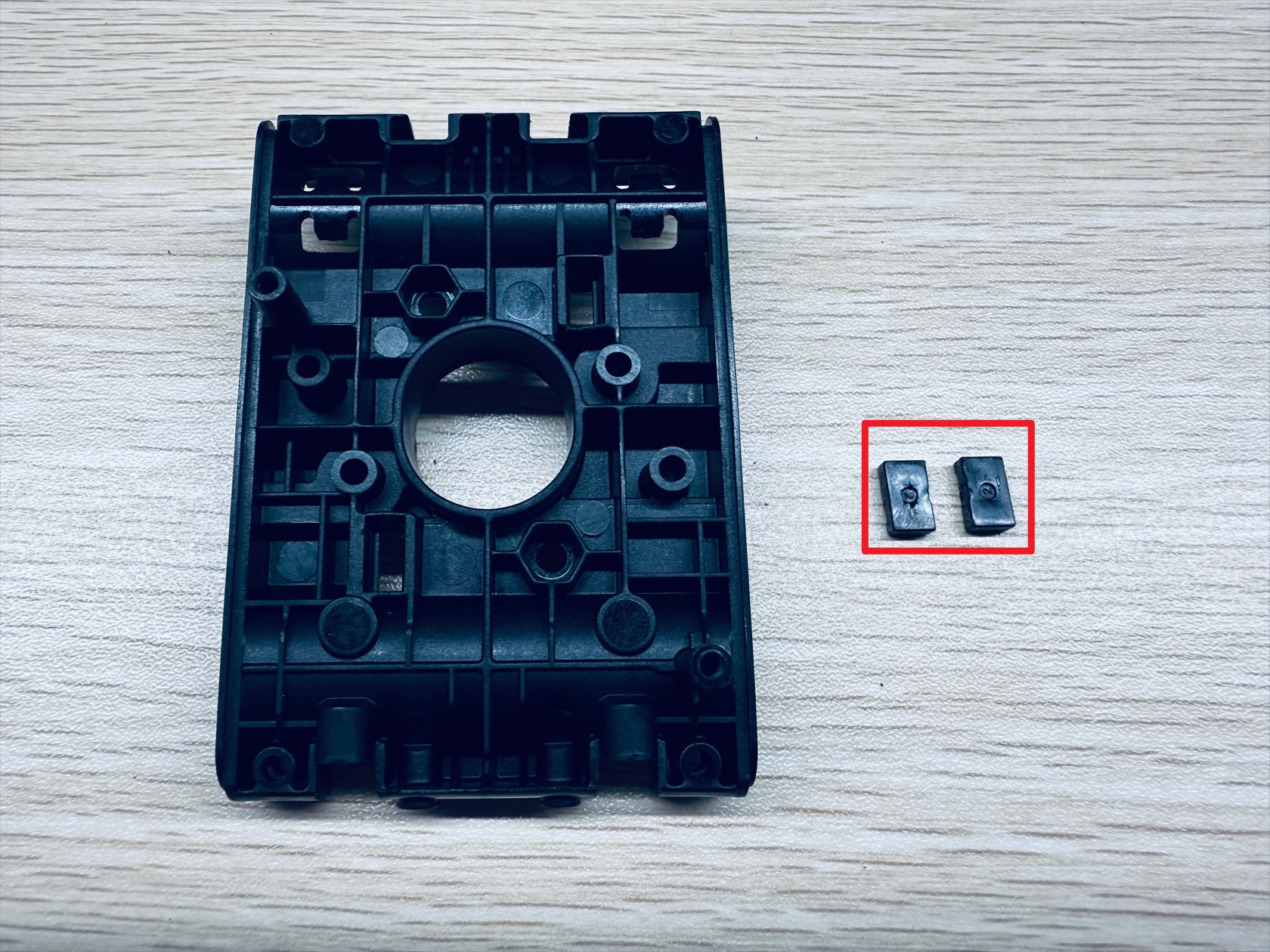
After removing the screws, the metal plates used to fix the carbon rod on both sides will fall off
-
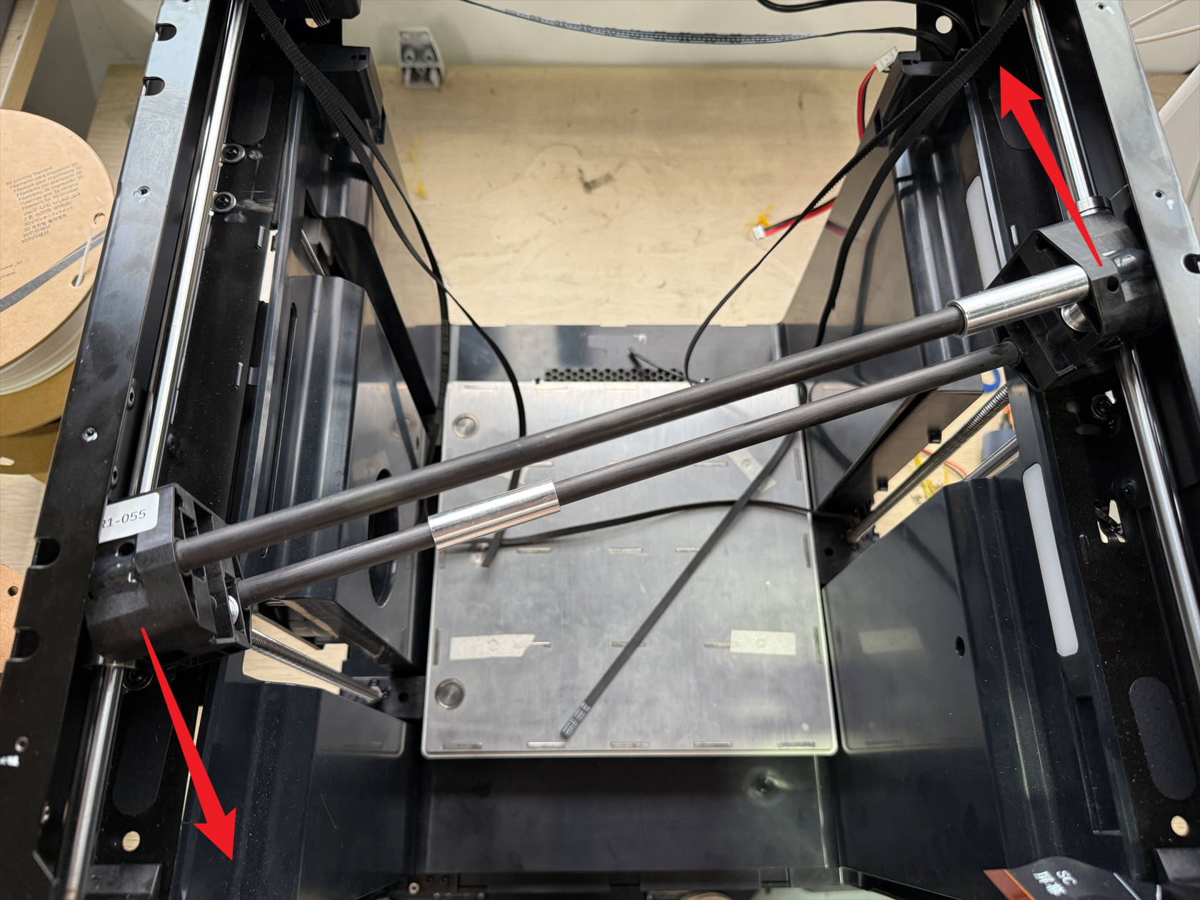
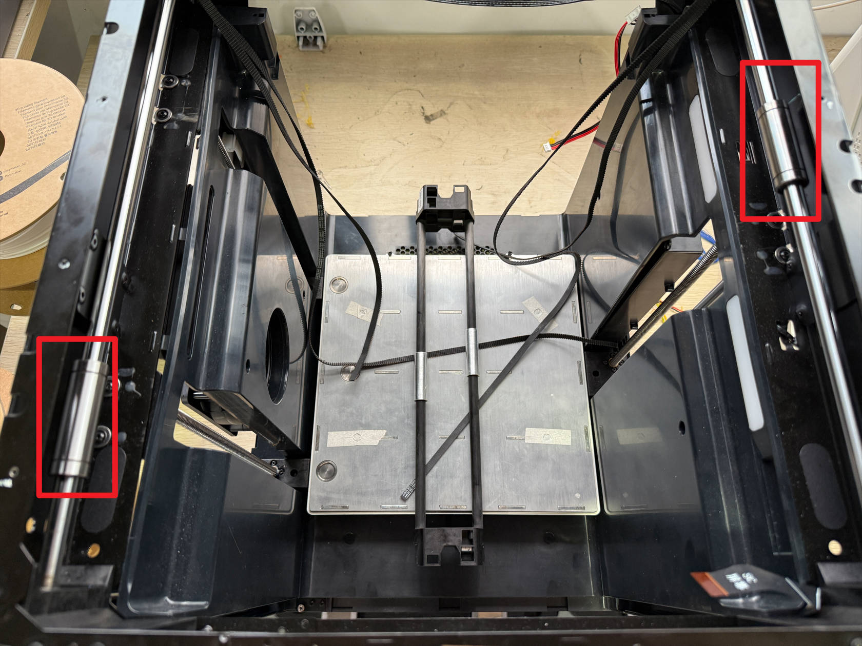
Remove the carbon rod following the illustration
-
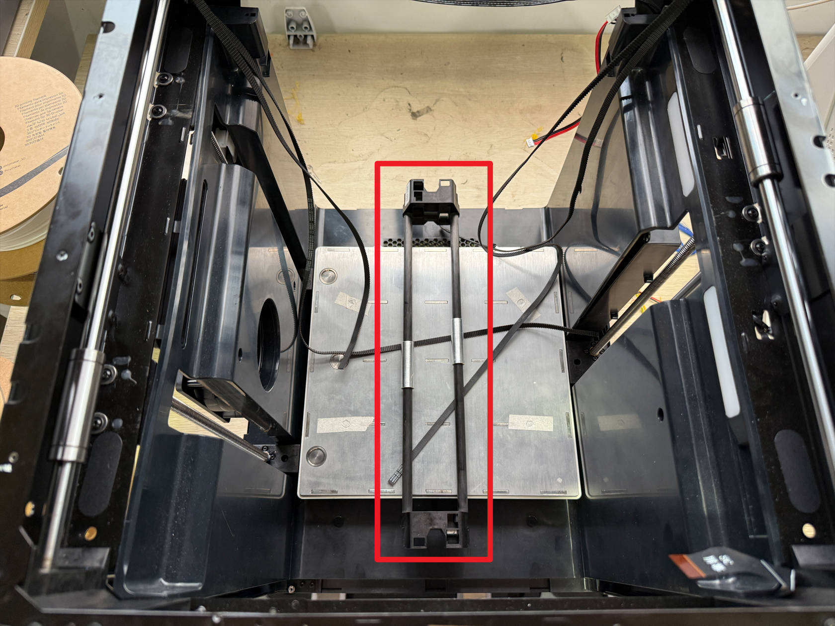
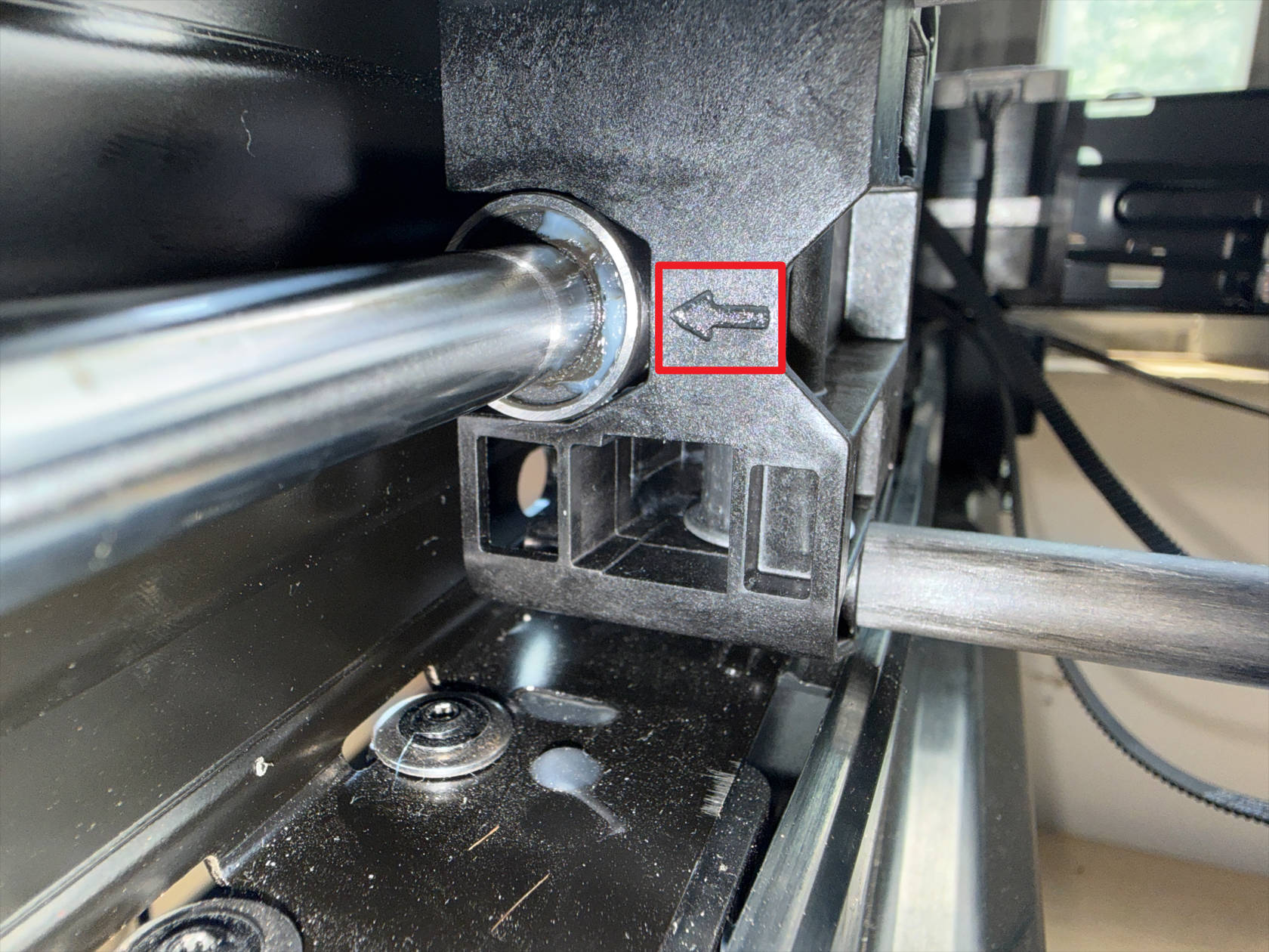
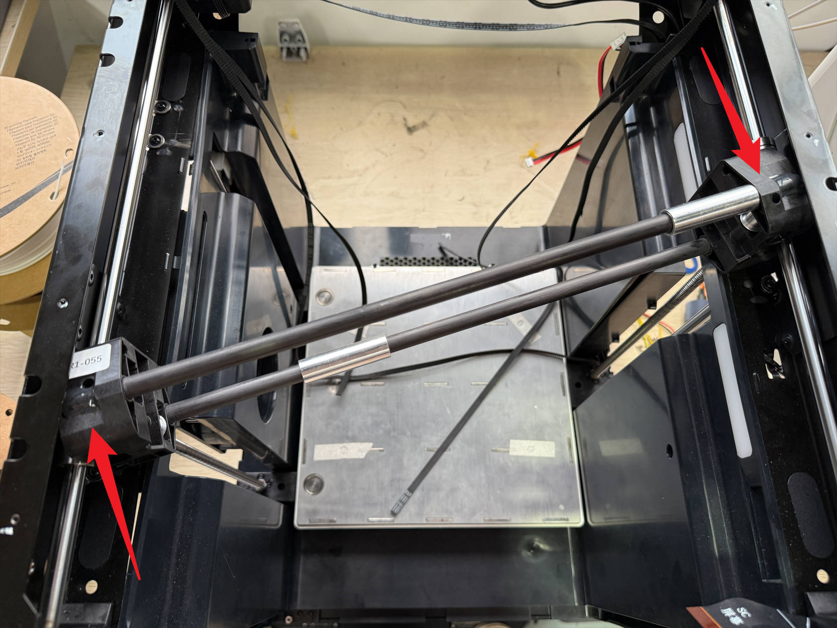
Install the carbon rod following the illustration, note the side of the carbon rod with the arrow should be closer to the front of the machine
-
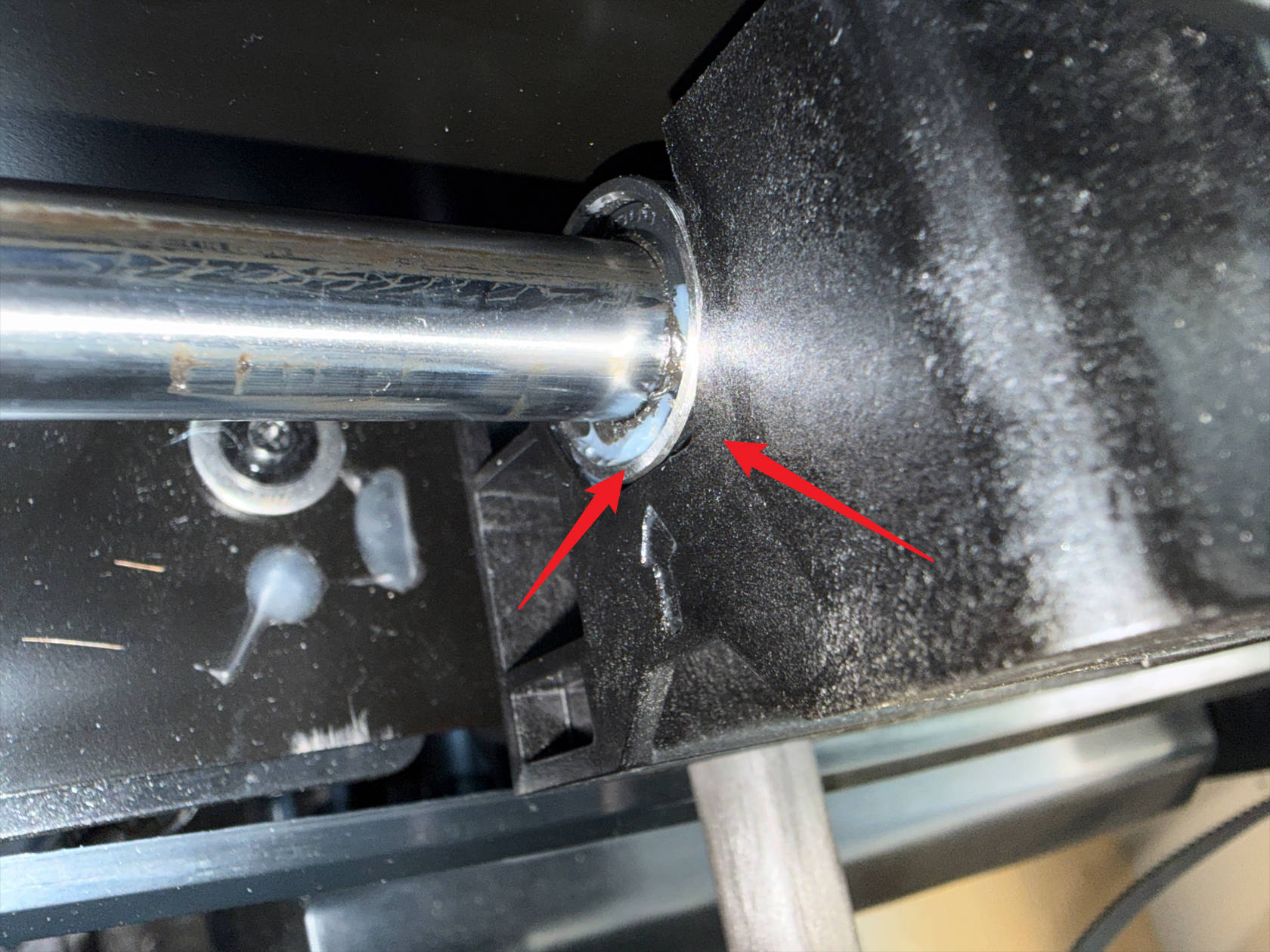
Adjust the carbon rod position so it is perpendicular to the Y-axis, and the Y-axis slider on the carbon rod side closest to the front of the machine is aligned with the linear bearing
-
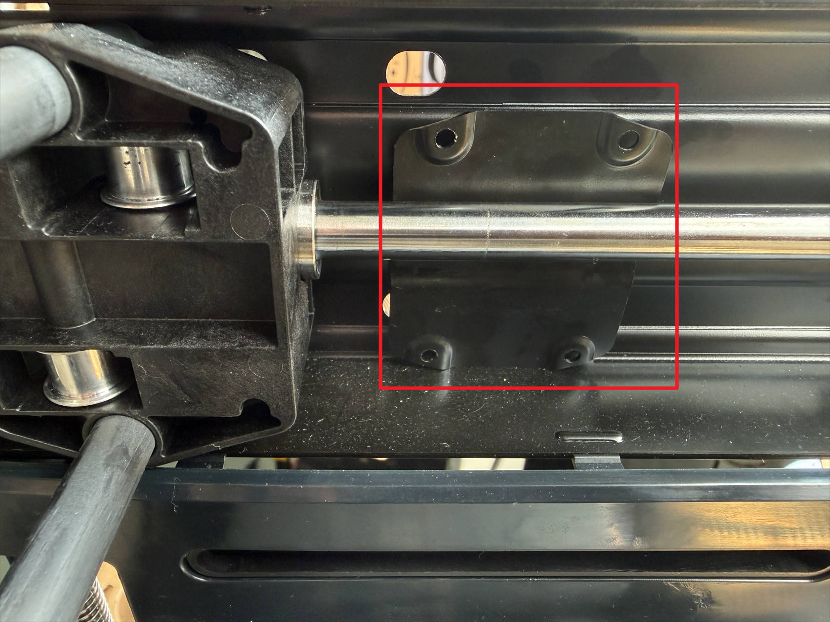
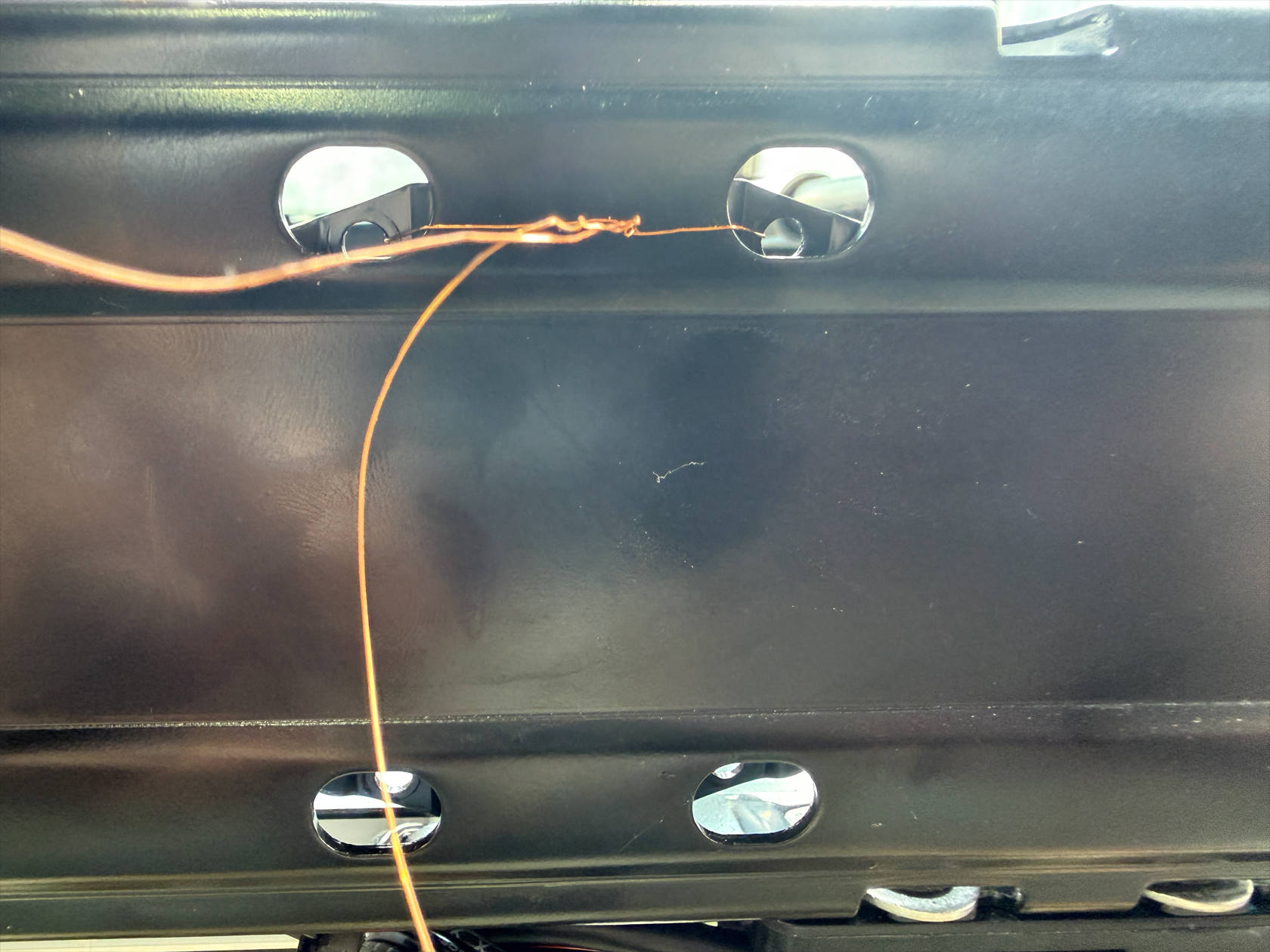
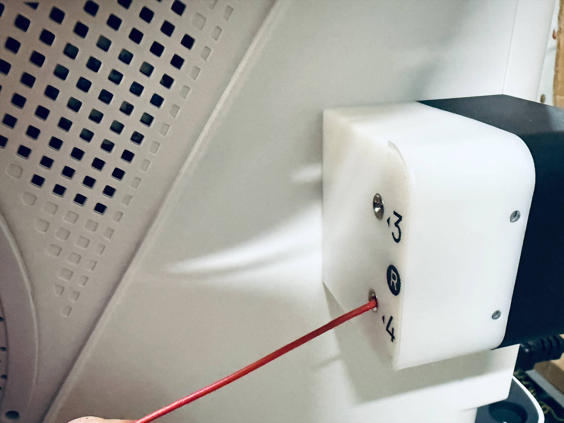
Use fine wire or copper wire to secure the metal plates on both sides of the Y-axis that were originally connected to the carbon rod, pass the wire through the holes on the top of the frame on both sides, through the corresponding holes on the metal plates, then out from the other end and fix it on the frame as shown
-
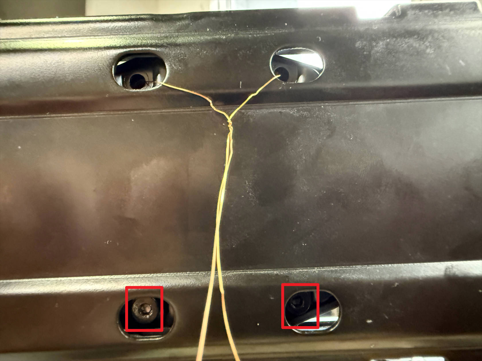
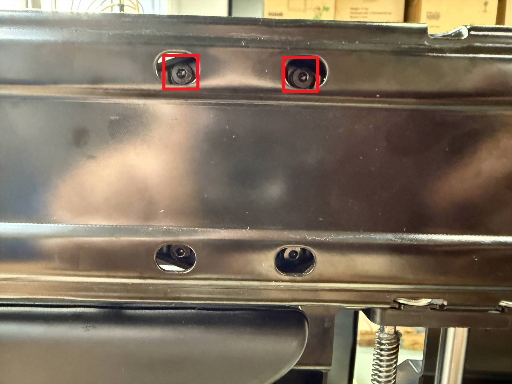
Use an H2.0 hex key to tighten 4 screws on each side of the frame, first tighten the 2 lower screws, then disconnect and remove the wire/copper wire, then tighten the 2 upper screws
¶ Step 6. Restore the toolhead swapper
-
Re-route the timing belt by following the instructions in U1 XY Belt Path Guide
-
Secure the timing belt and reinstall the toolhead swapper by following the instructions in How to Reinstall the XY Belt
¶ Step 7. Install the printer casing
-
Pass the FFC cable through the reserved window in the frame, install the front panel, use an H2.0 hex key to tighten a total of 10 screws on the front panel and 2 screws on the glass door hinge
-
Restore the screen FFC cable, install the screen rear cover
-
Restore the RFID cable at point 1, pass the filament feeder cable through point 2, install the left plastic panel
-
Use an H2.0 hex key to tighten 8 screws on the left plastic panel
Tighten screws 1—4
Tighten screws 5—6 in the holes corresponding to the filament holder
Tighten screws 7—8 on the left inner panel
-
Restore the RFID cable at point 1, pass the filament feeder cable through point 2, install the right plastic panel

-
Use an H2.0 hex key to tighten 8 screws on the right plastic panel
Tighten screws 1—4
Tighten screws 5—6 in the holes corresponding to the filament holder
Tighten screws 7—8 on the right inner panel
- Install the top cover panel, use an H2.0 hex key to tighten 4 screws, and reinstall the silicone plugs
¶ Step 8. Install the filament feeders and spools
-
The installation method for the right-side filament feeder and filament holder is as follows
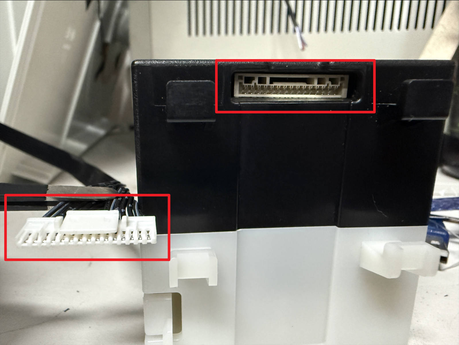 Orient the cable terminals and connectors as shown
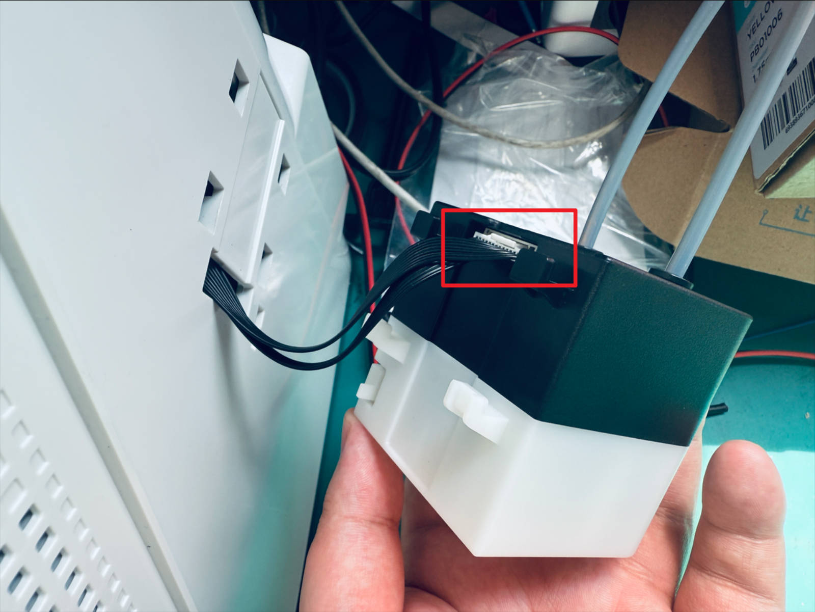 Restore the filament feeder wiring
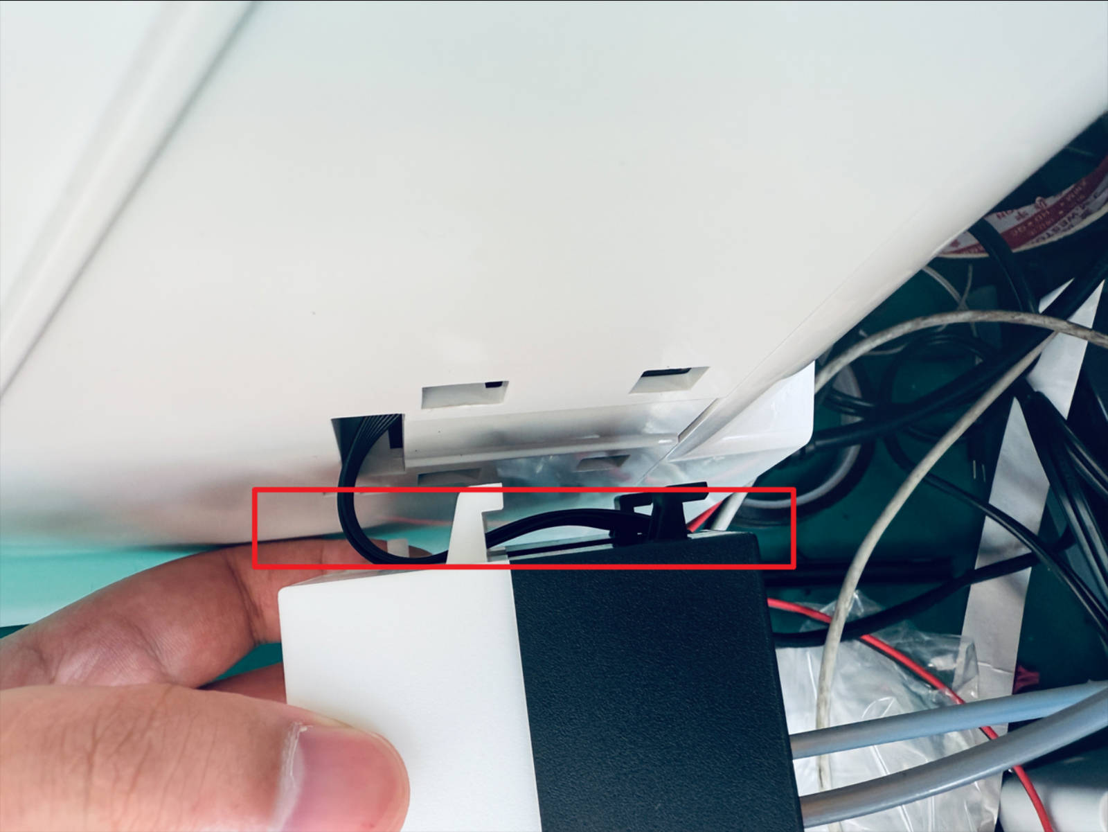 Route the cables as shown
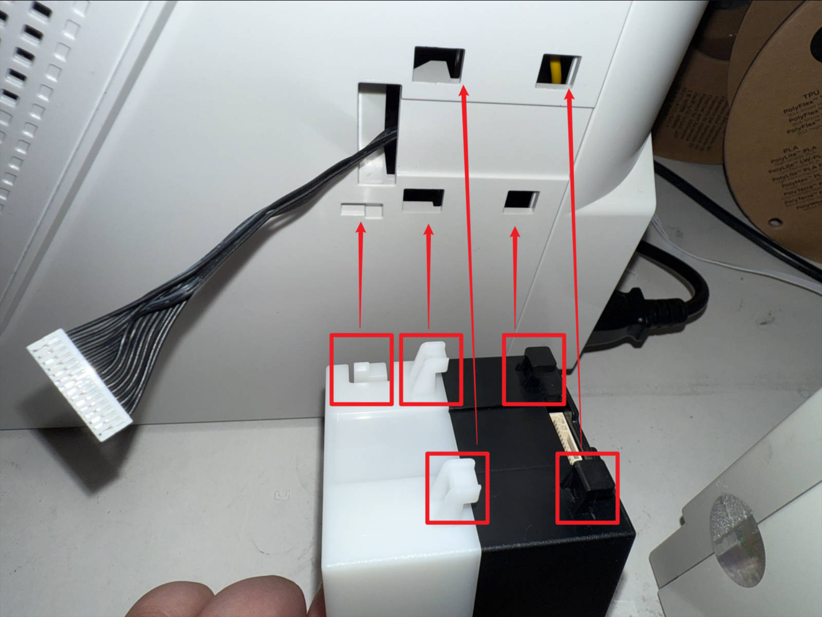 Align the clips to the corresponding positions as shown, install the filament feeder
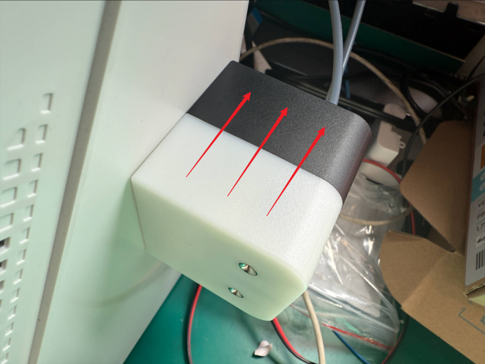 Push the filament feeder into place following the illustrated direction
Connect the two 4 mm filament tubes from the filament feeder to the quick connectors at the back of the machine
Push the filament feeder into place following the illustrated direction
Connect the two 4 mm filament tubes from the filament feeder to the quick connectors at the back of the machine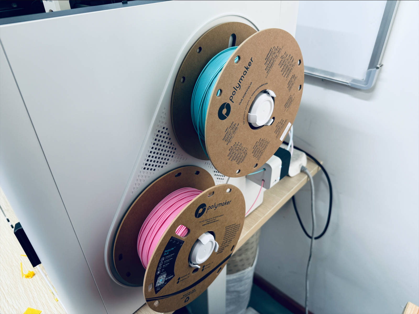 Install the spools
- Install the left-side filament feeder and filament holder in the same way
¶ Step 9. Load filament
-
Power on the printer


-
Insert the filaments into their corresponding filament feeders
-
Tap the indicated position on the touchscreen
-
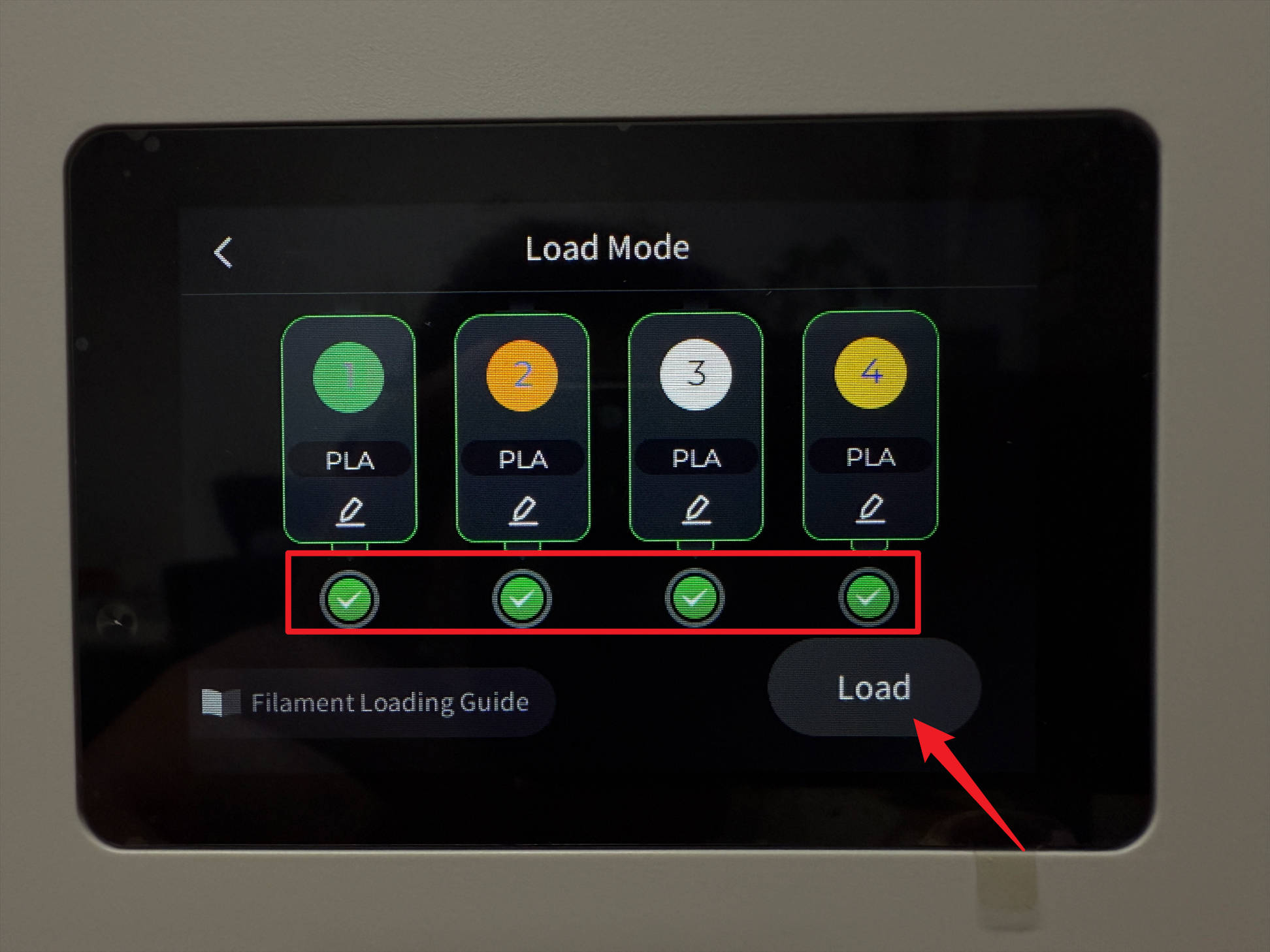
Tap Load Mode
-
Select all toolheads, tap Load, note that unrecognized filaments need to have type and color manually adjusted, save changes to complete loading
-
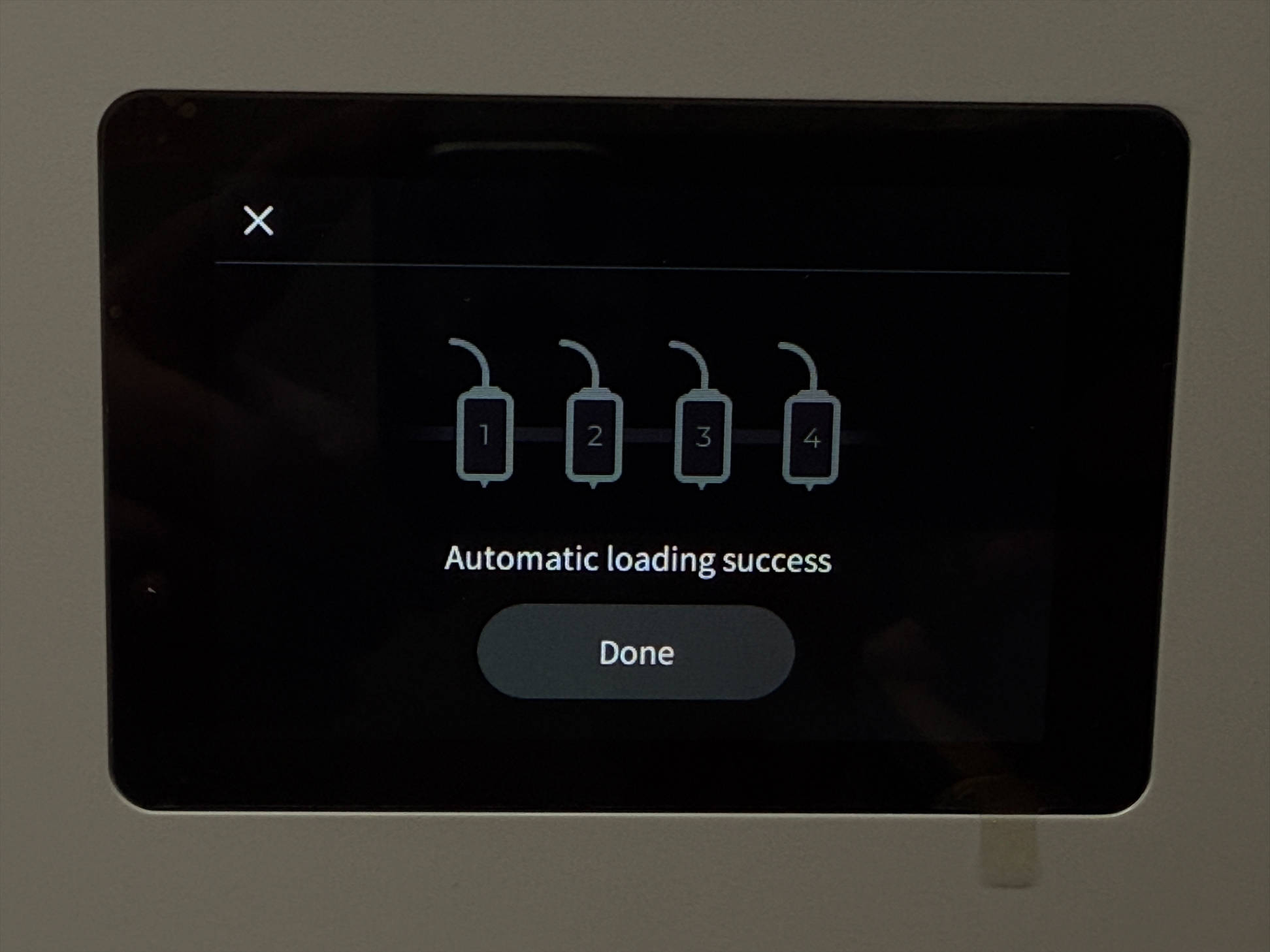
Wait for the automatic filament loading to finish

¶ Reach out to Snapmaker Support
After following the troubleshooting steps, if you find it difficult to resolve your issue, kindly submit a support ticket through https://snapmaker.formcrafts.com/u1-troubleshooting-request and share your troubleshooting results with some pictures/videos.
Our dedicated support team will be more than willing to assist you in resolving the issue.