¶ Overview
¶ Structural description
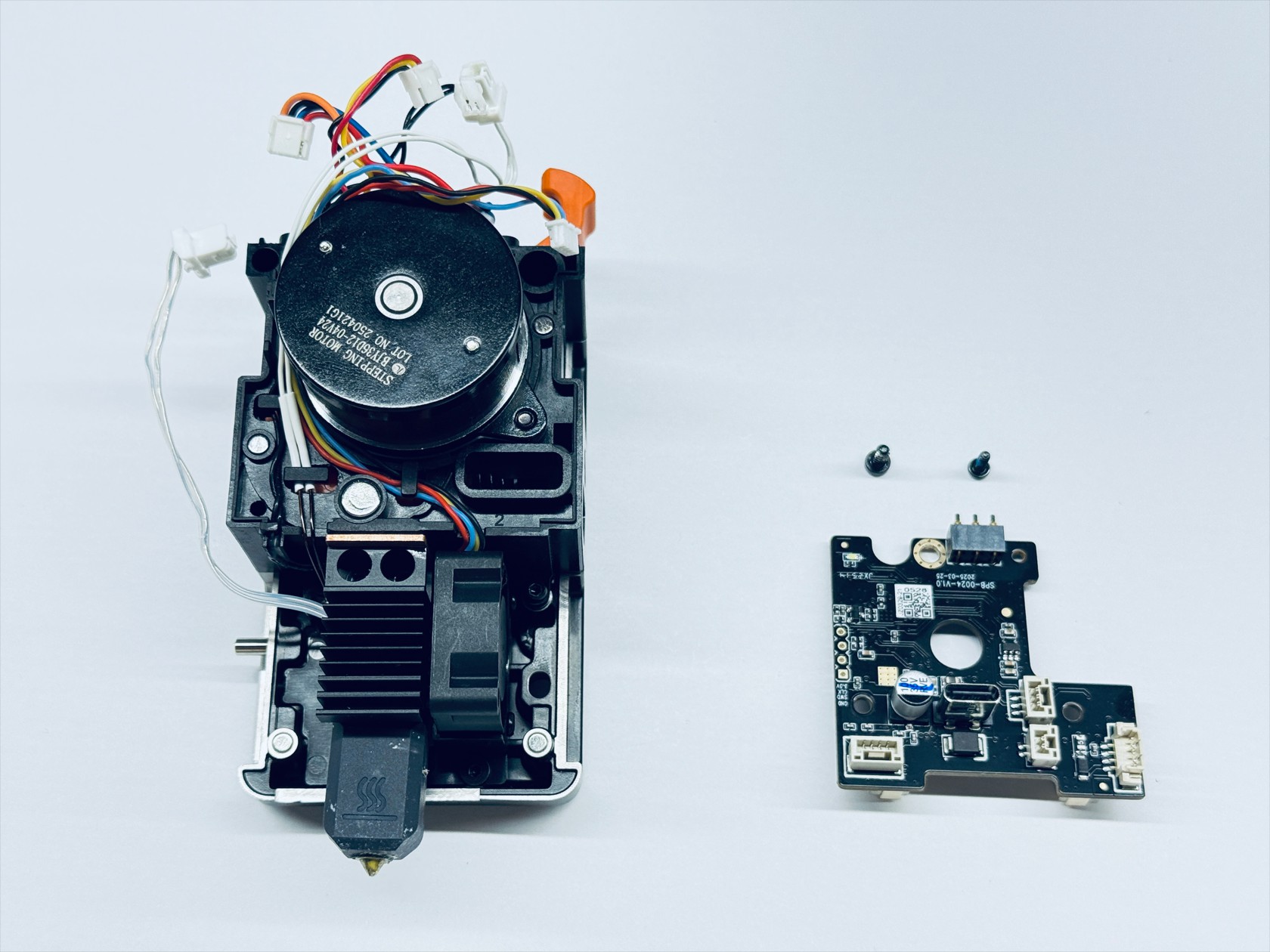
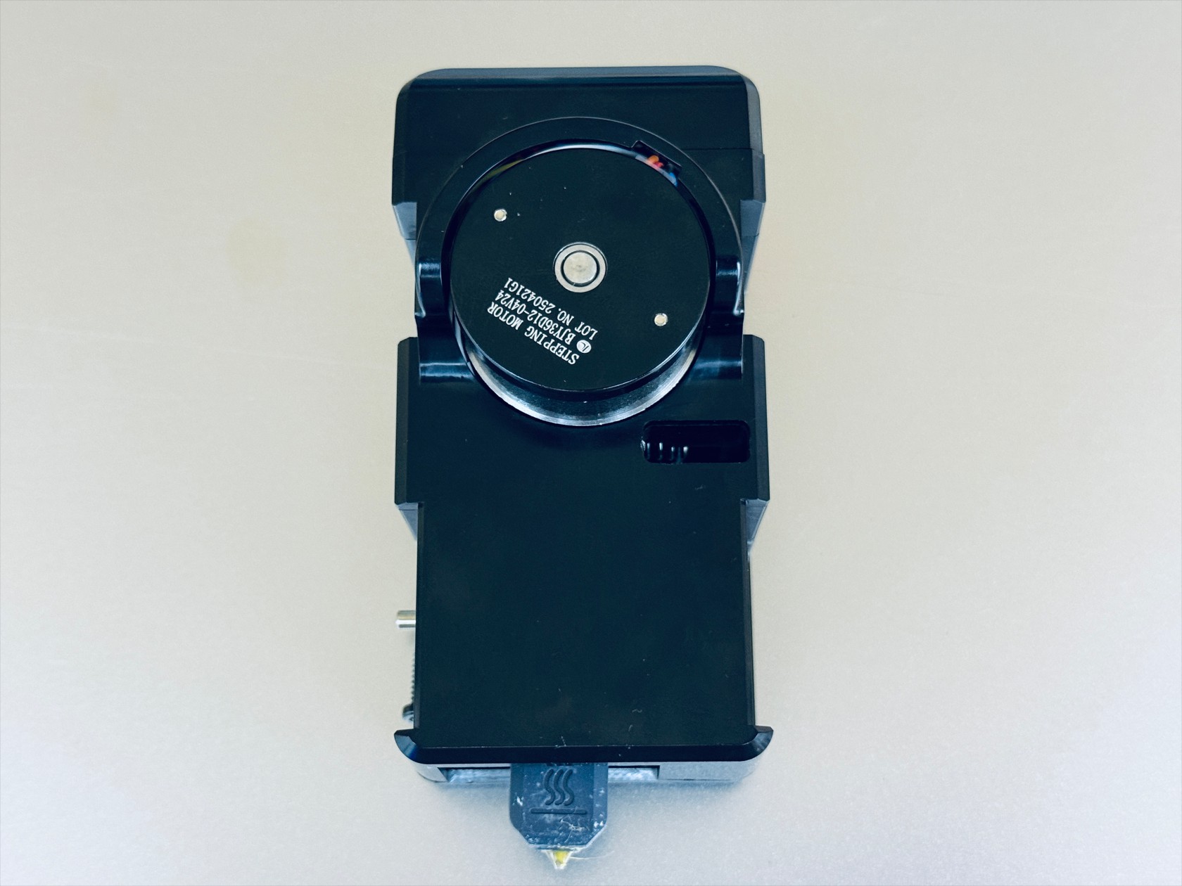
- The toolhead can be broadly divided into 5 functional parts: cover, male mount, extruder unit, hotend, control board.
Disassembly and reassembly must be performed in the specified order.
Please read the steps below in full before attempting any operations.
¶ Difficulty and Time Estimate
- Difficulty:★★★☆☆ (moderate)
- Estimated Time:40mins
¶ Tools and Parts Required
- H2.0 hex key
- H1.5 hex key
¶ Toolhead disassembly
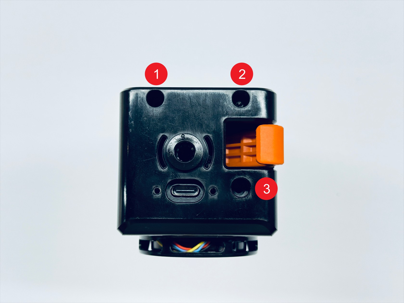
¶ Step 1. Remove the toolhead cover
- Use an H2.0 hex key to unscrew the three screws and remove the top cover & the rear cover

¶ Step 2. Remove the toolhead control board
-
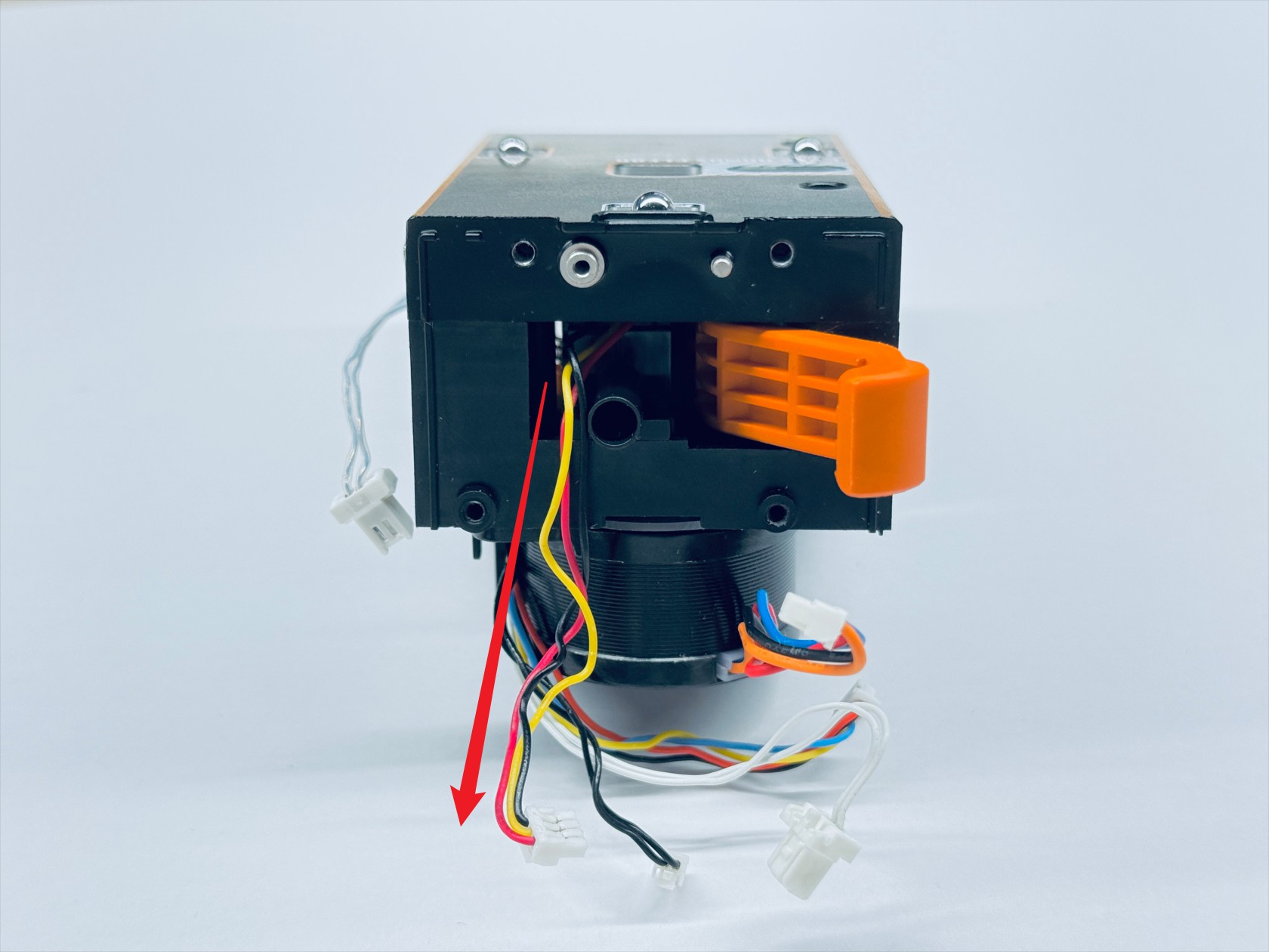
Disconnect the 6 cables of the toolhead control board
NO. Name 1 Extruder motor cable 2 Filament runout sensor cable 3 Calibration sensor cable 4 Hotend cooling fan cable 5 Ceramic heater cable 6 Thermistor cable Toolhead control board wiring guide(1/3)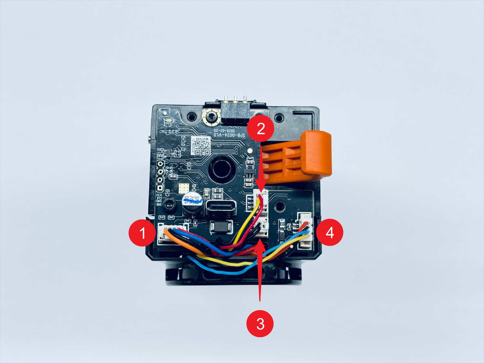 Toolhead control board wiring guide(2/3)
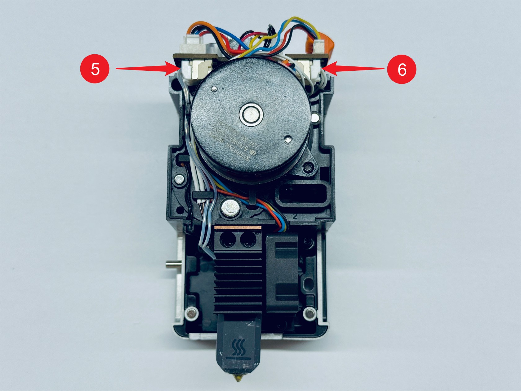 Toolhead control board wiring guide(3/3)
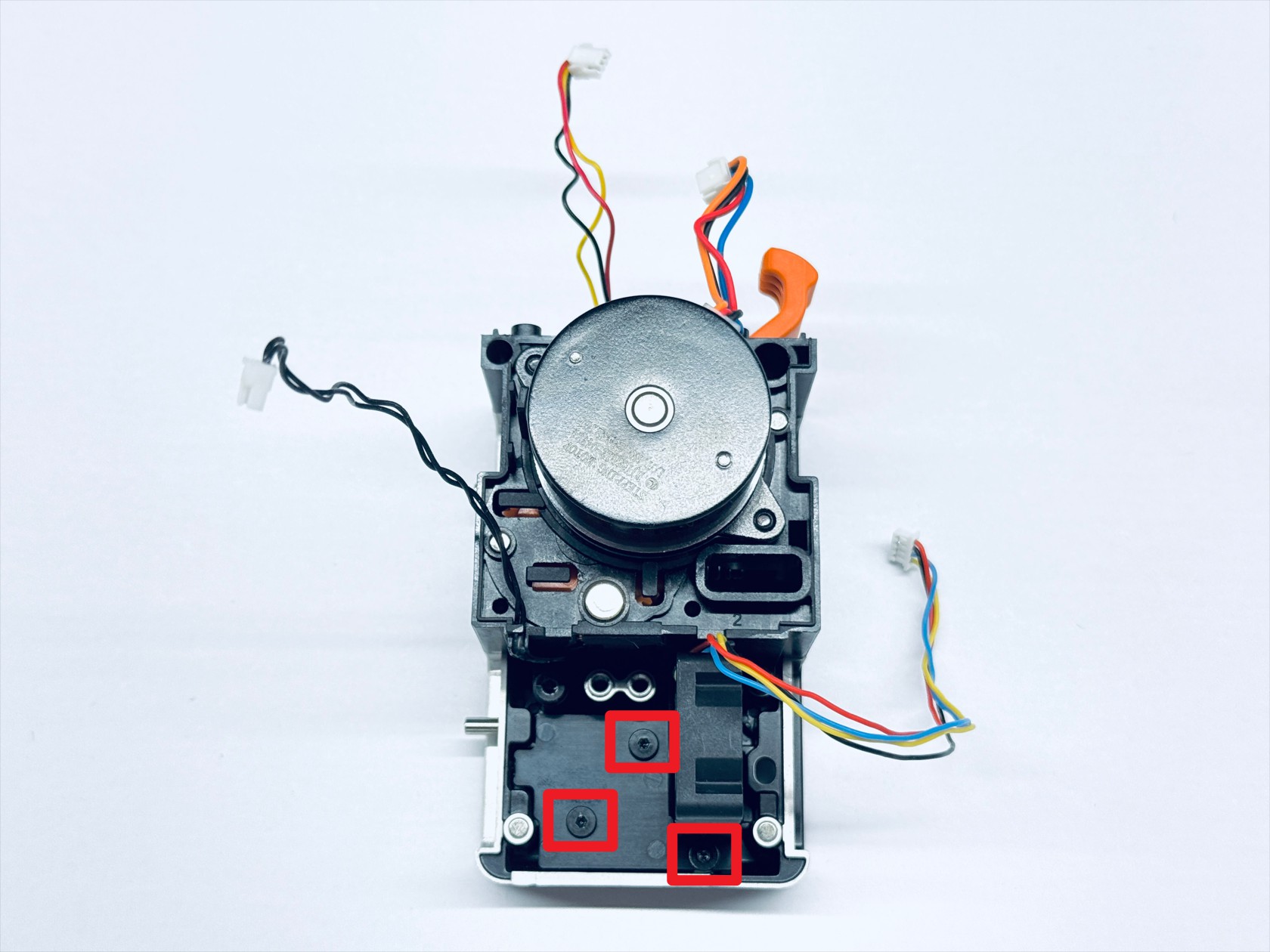
- Use H1.5 and H2.0 hex keys respectively to unscrew screws 1 and 2, then remove the toolhead control board
¶ Step 3. Disassemble the hotend
-
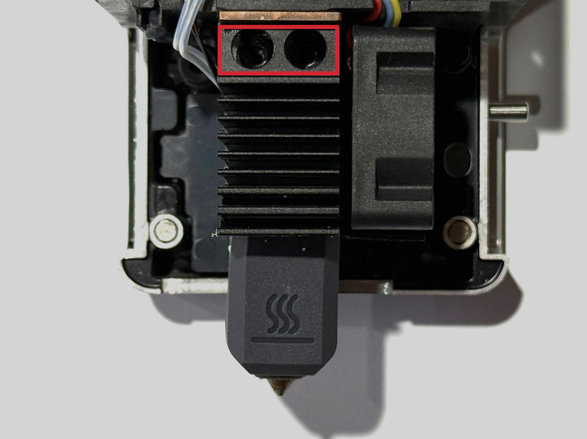
Use an H2.0 hex key to unscrew the 2 fixing screws and remove the hotend
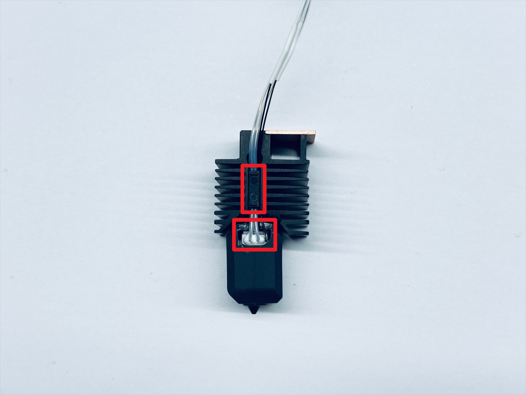
-
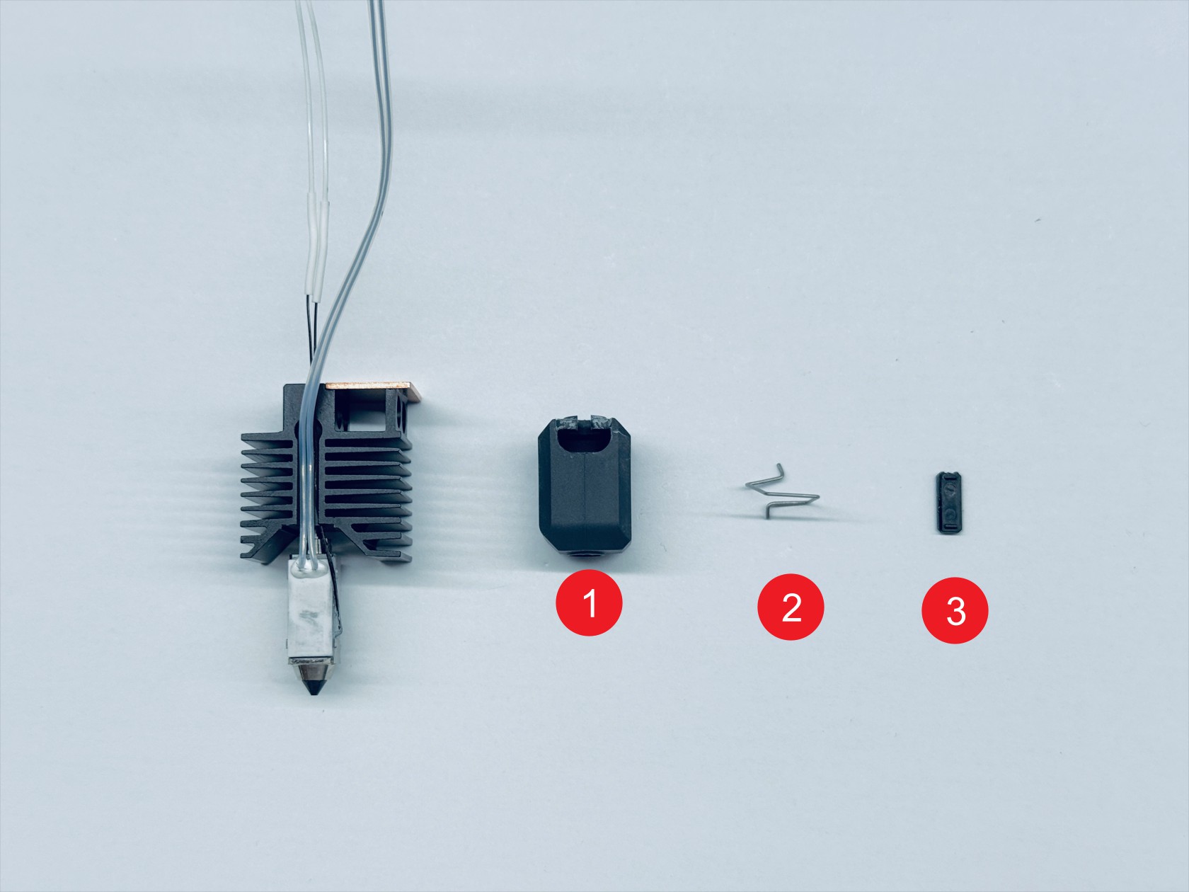
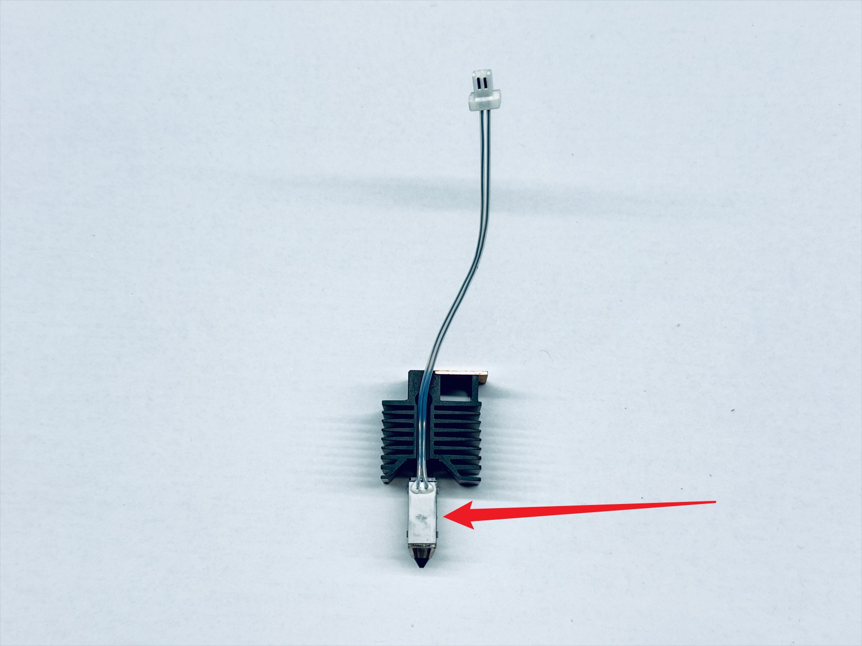
Remove the hotend silicone sock-1, ceramic heater spring clip-2, and cable holder-3 in sequence
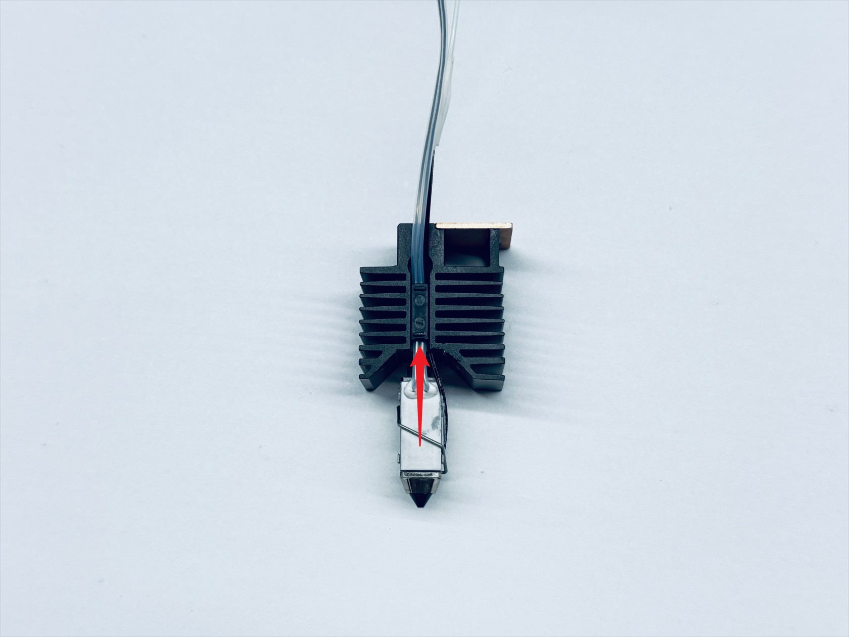
-
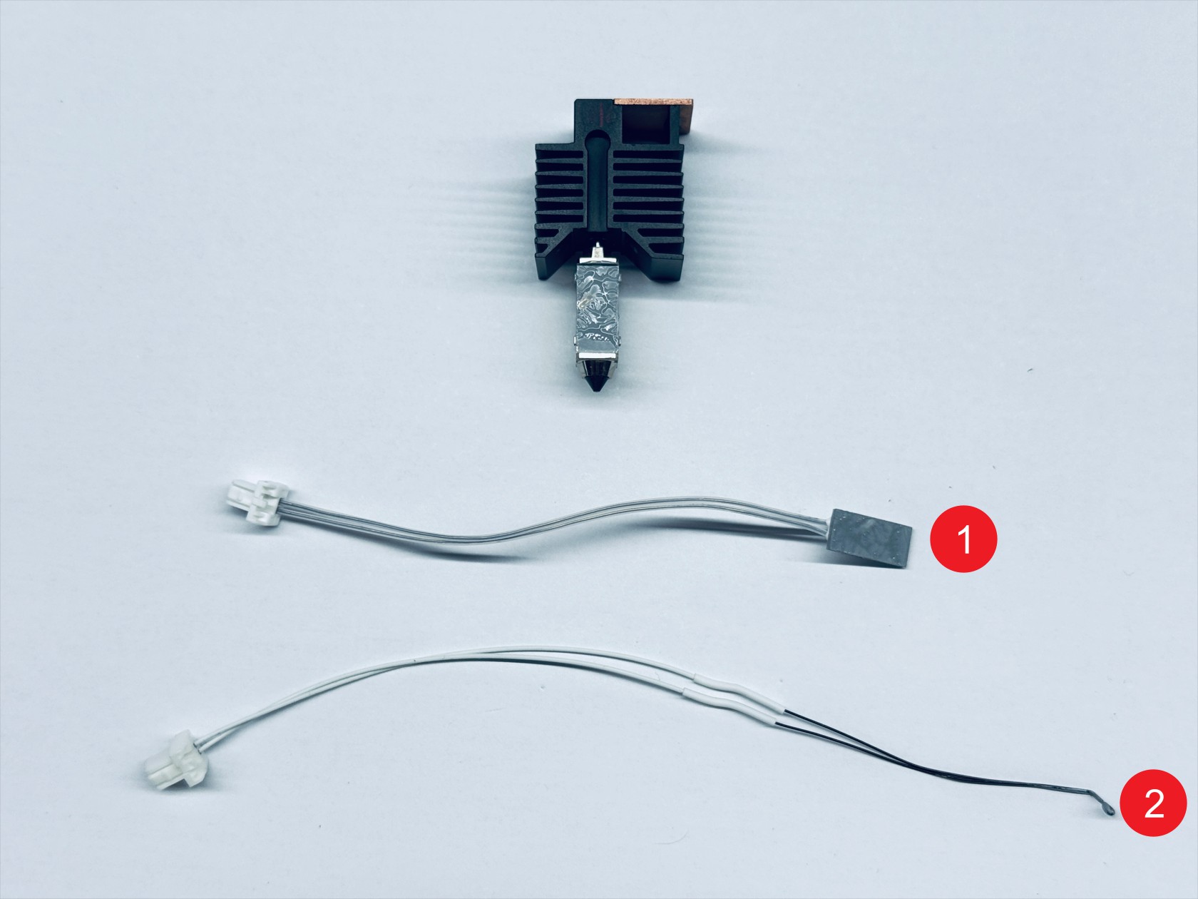
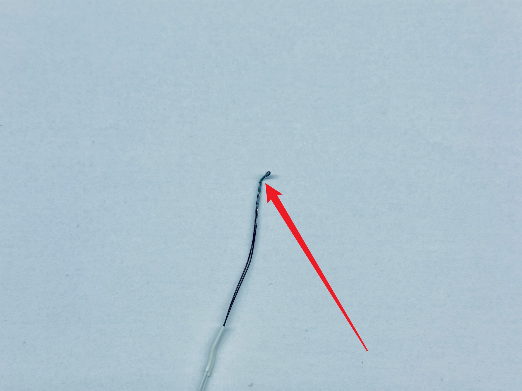
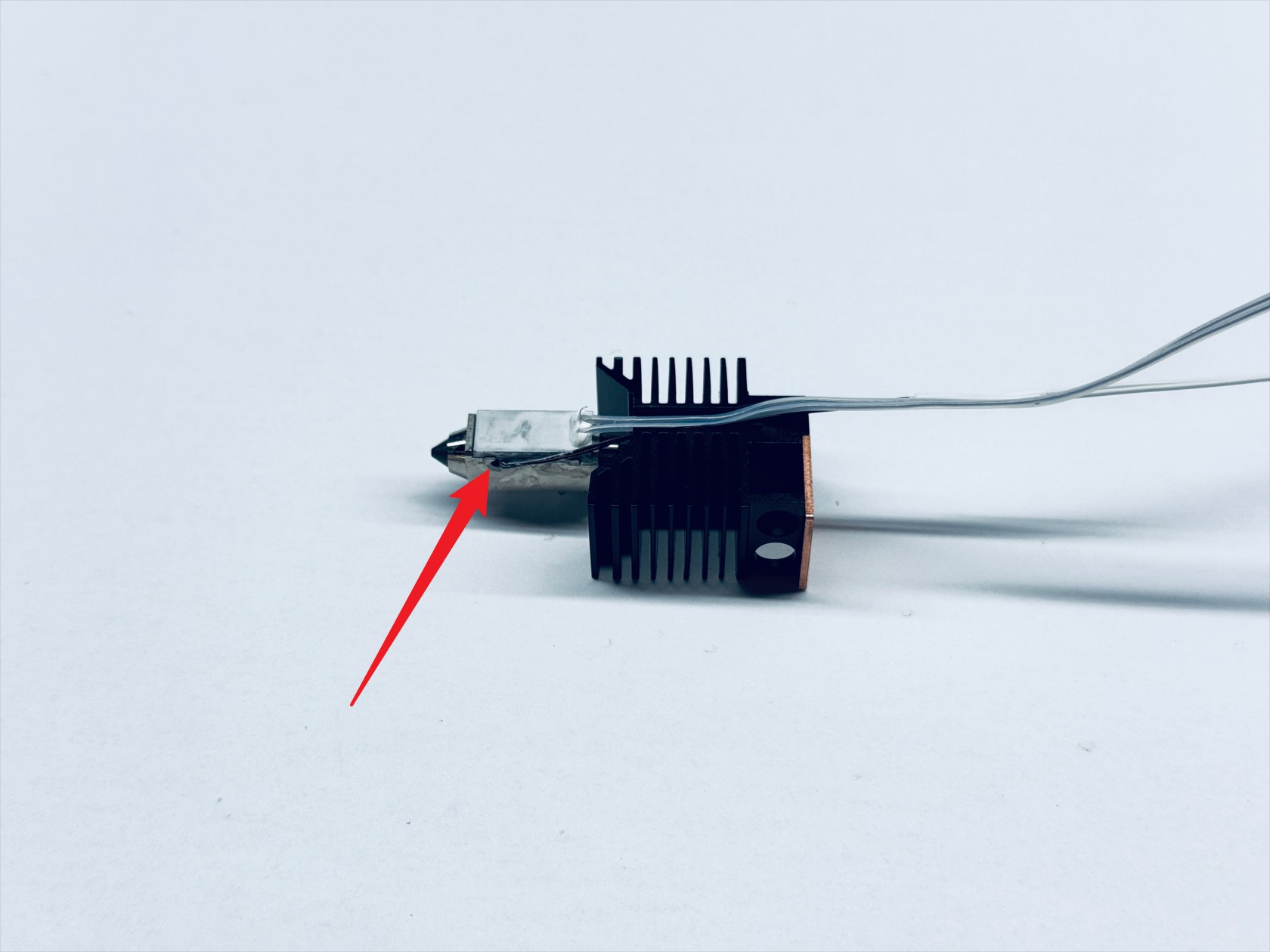
Remove the ceramic heater-1 and thermistor-2 in sequence
¶ Step 4. Disassemble the hotend cooling assembly
-
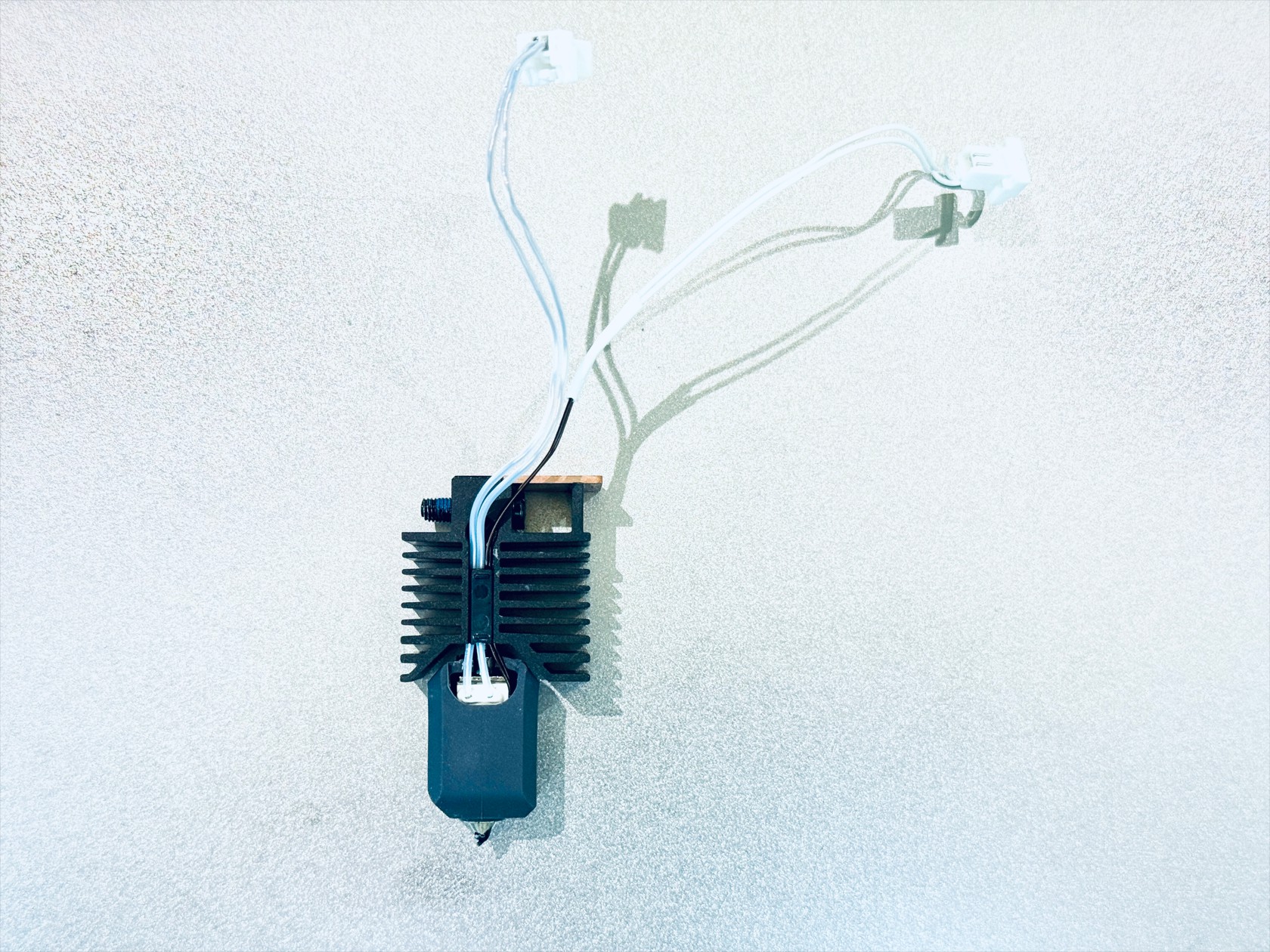
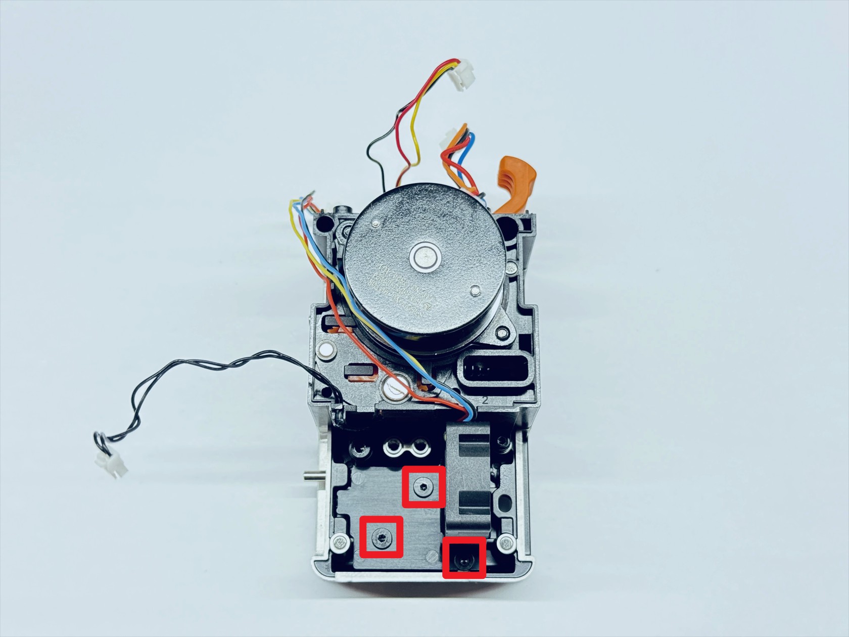
Use an H1.5 hex key to unscrew the 3 fixing screws and remove the hotend cooling assembly
-
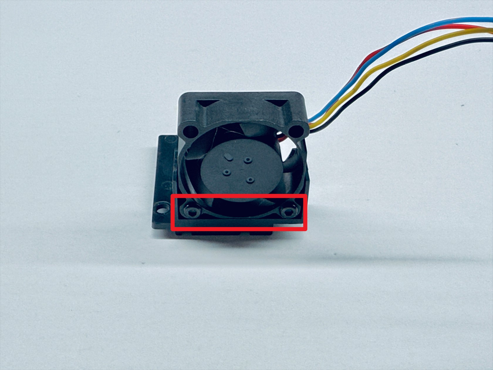
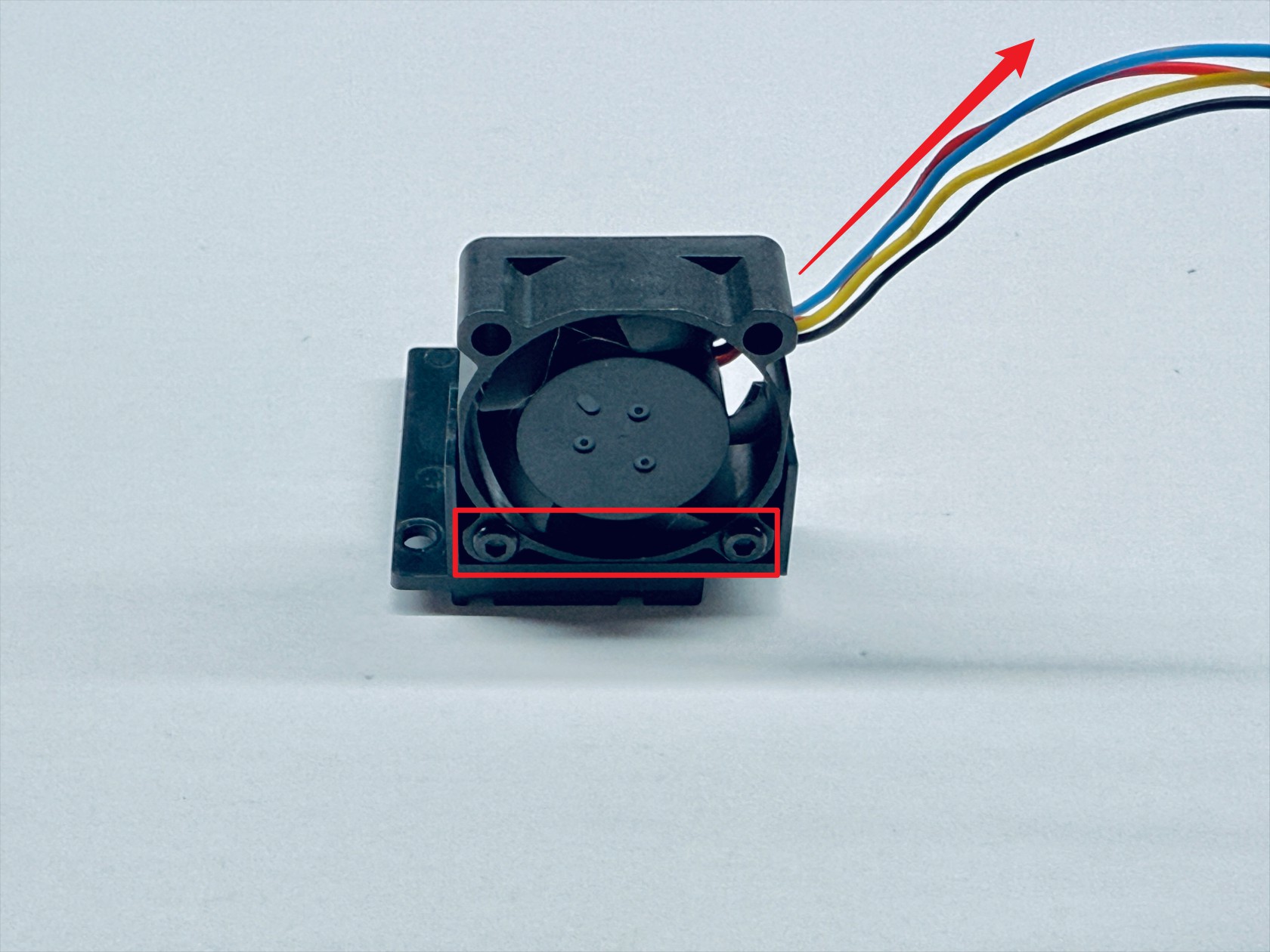
Use an H1.5 hex key to unscrew the 2 fixing screws and remove the hotend cooling fan
¶ Step 5. Disassemble the extruder unit
-
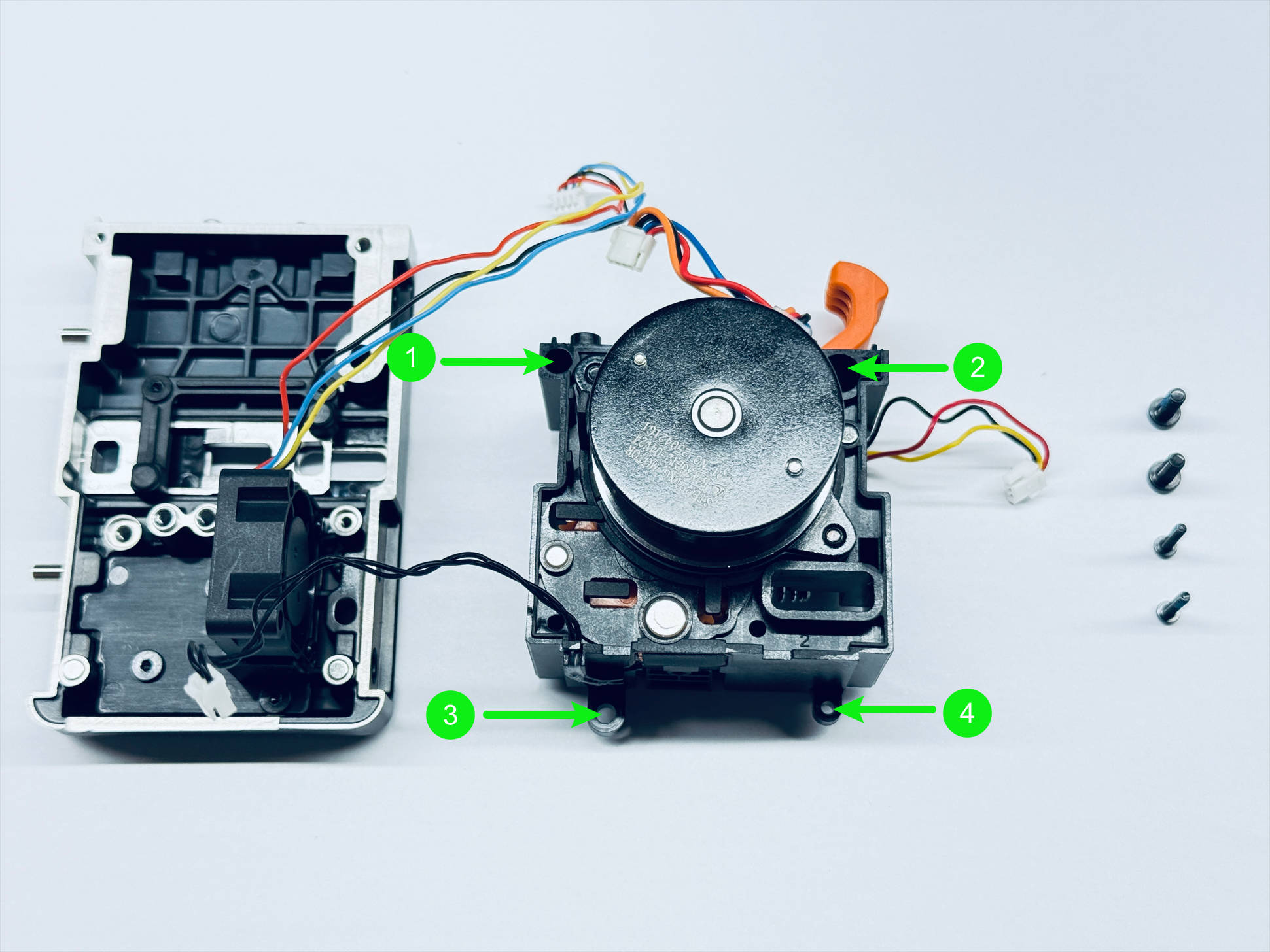
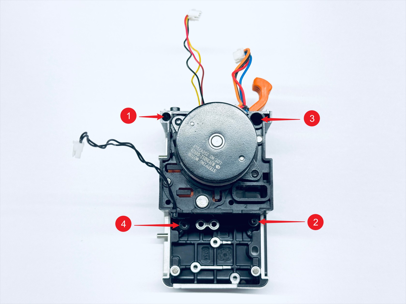
Use H1.5 & H2.0 hex key to unscrew the 4 fixing screws and remove the extruder unit.
-
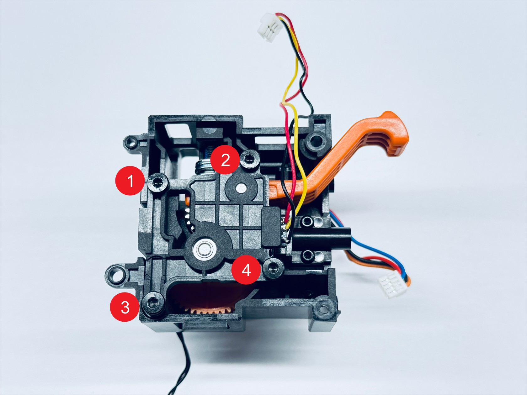
Use an H2.0 hex key to unscrew the 4 fixing screws and remove the extruder bearing holder
-
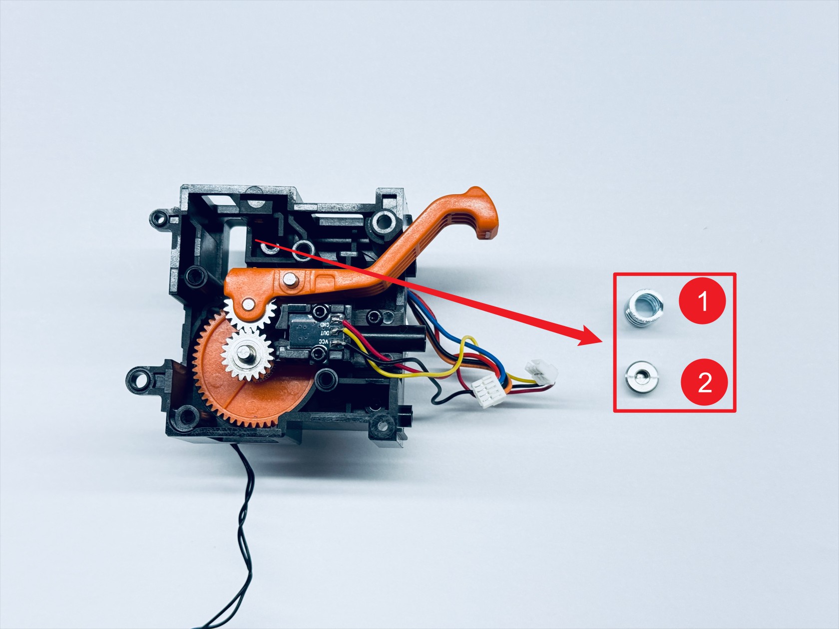
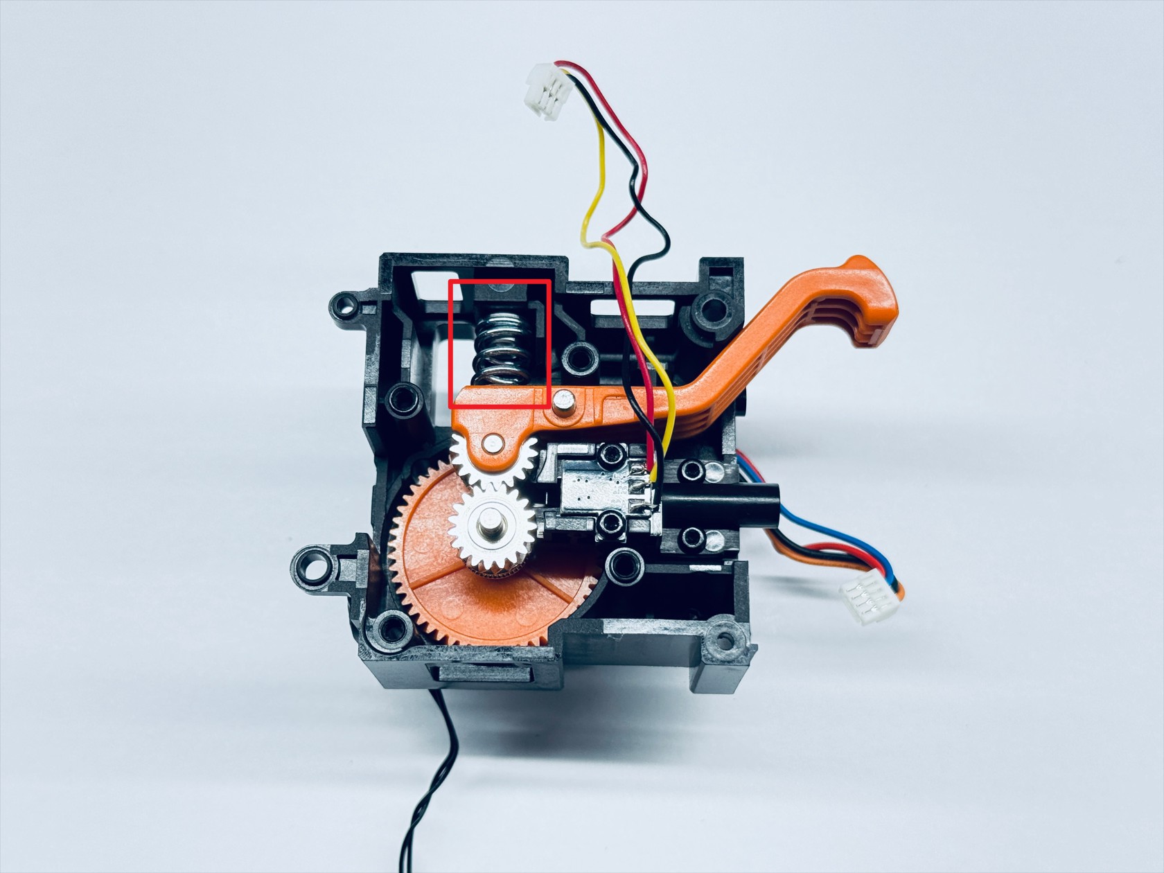
Use an H2.0 hex key to unscrew the spring fixing screw and remove the compression spring—1 and the spring block—2

-
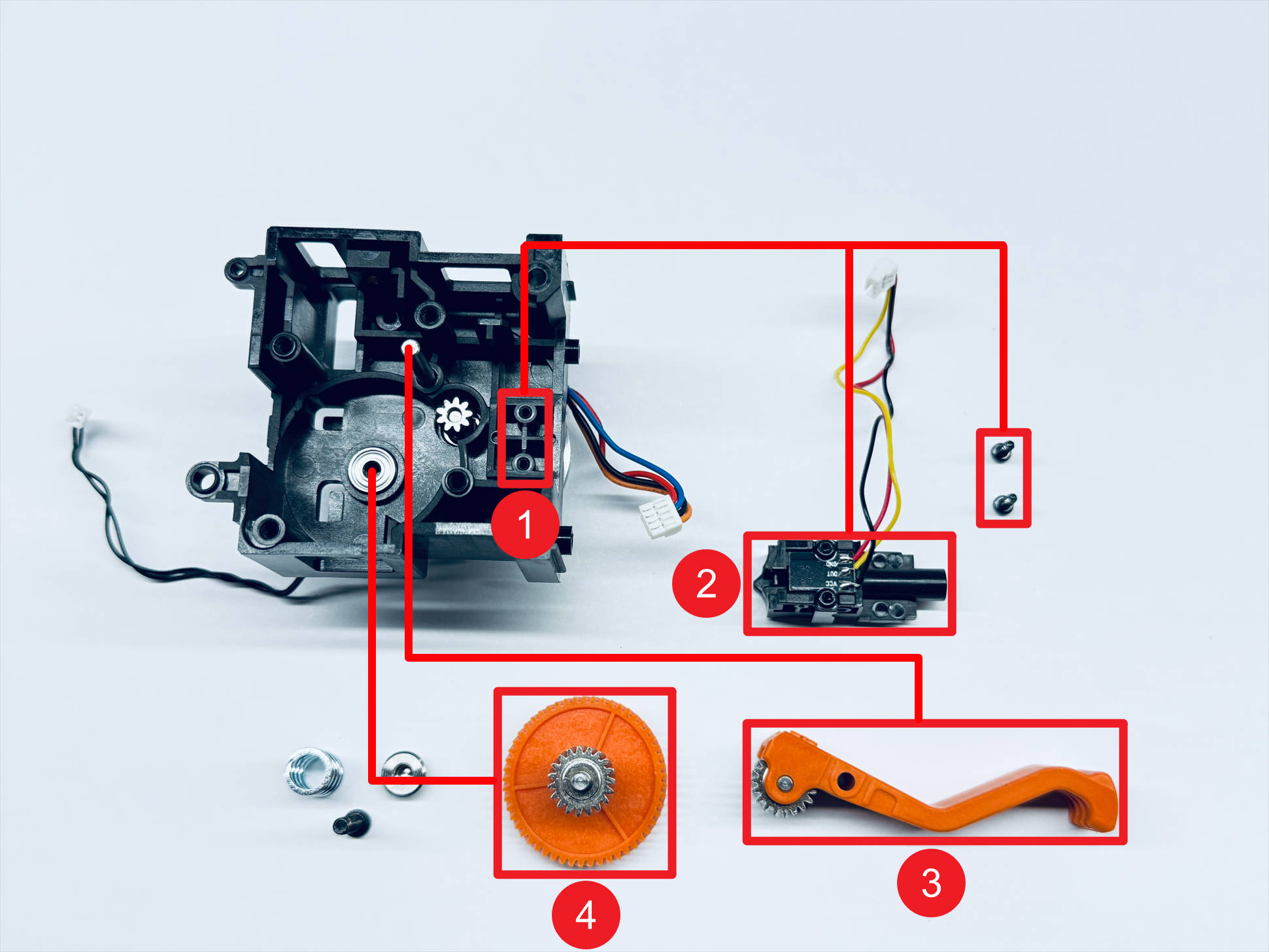
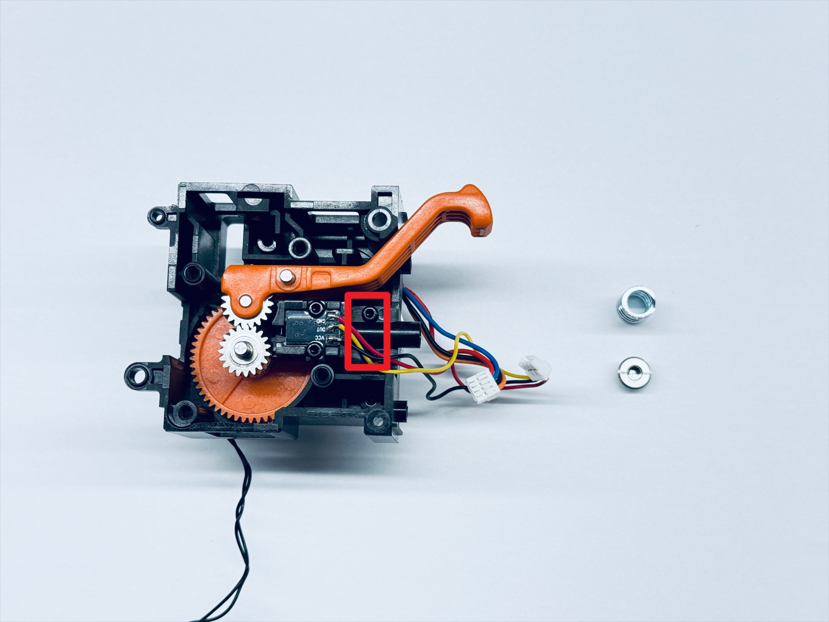
Use an H1.5 hex key to unscrew the 2 fixing screws and sequentially remove the filament runout sensor—2, the driven extruder assembly—3, and the driving extruder assembly—4
-
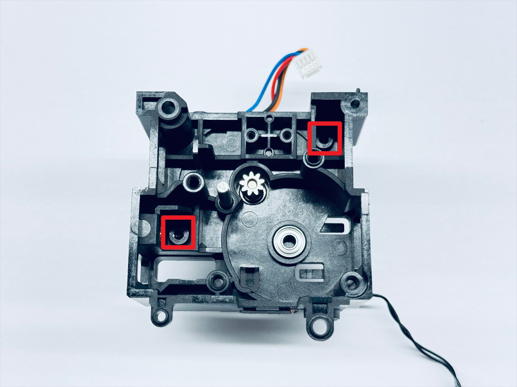
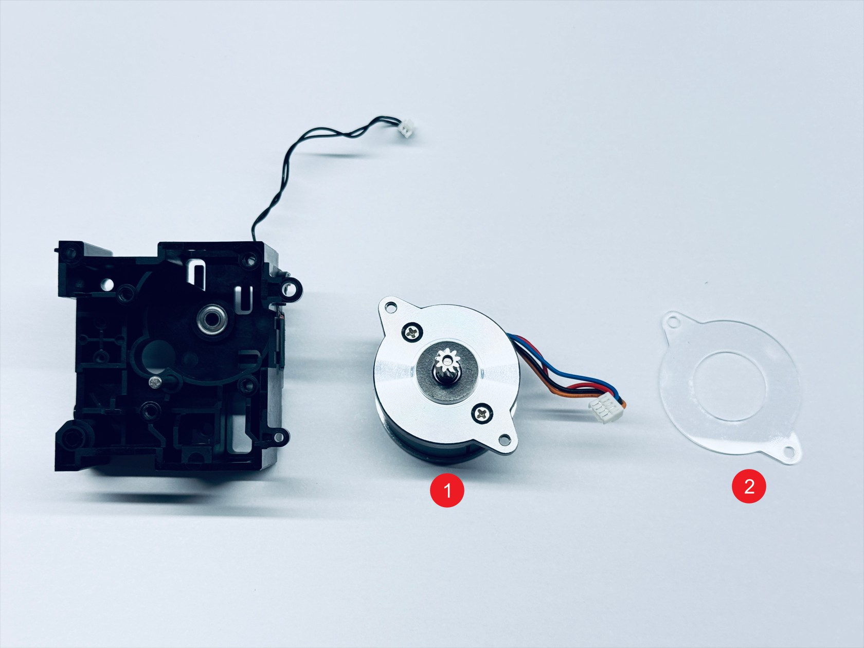
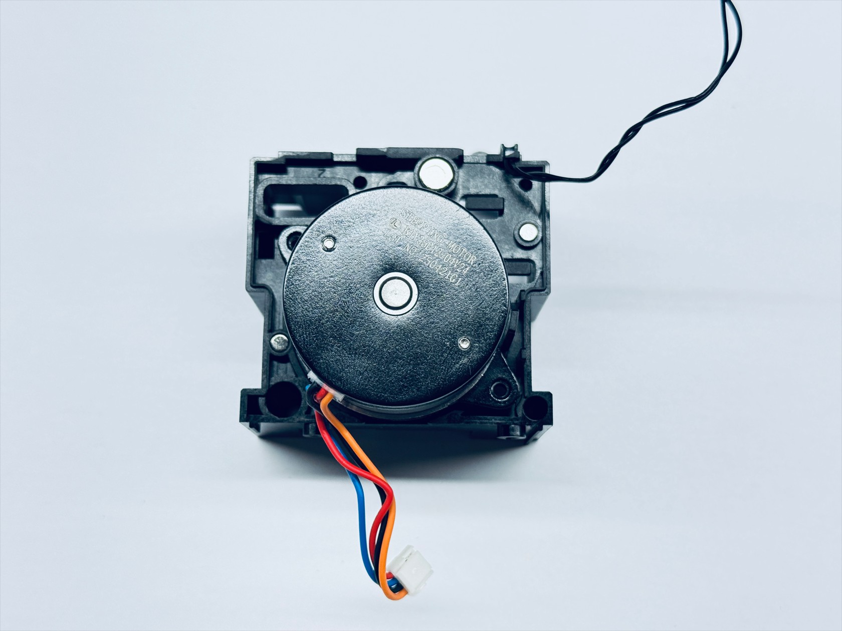
Use an H2.0 hex key to unscrew the 2 fixing screws and remove the extruder motor—1 and the motor heat shield—2
¶ Toolhead assembly
¶ Step 1. Assemble the extruder unit
-
Install the motor heat shield and the extruder motor in the orientation shown(Ensure that the position of the extruder motor cable matches the illustration), and use an H2.0 hex key to tighten the 2 fixing screws
-
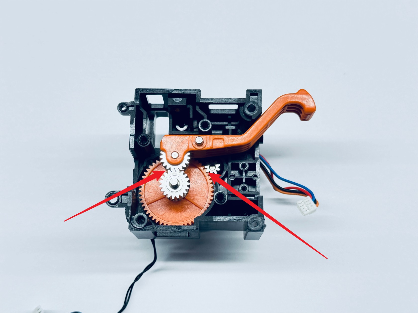
Install the driving extruder assembly and the driven extruder assembly sequentially, ensuring that the 3 gears shown mesh correctly. Rotate the active extruder gear to confirm that the other two gears turn smoothly, indicating proper installation
-
Install the filament runout sensor and use an H1.5 hex key to tighten the 2 fixing screws
-
Install the compression spring and spring block, placing the spring block above the compression spring, and use an H2.0 hex key to tighten the spring fixing screw
-
Reinstall the extruder bearing holder and use an H2.0 hex key to tighten the 4 fixing screws
-
Mount the assembled extruder unit back onto the toolhead male mount in the orientation shown, and use H1.5 and H2.0 hex keys to tighten fixing screws 1, 2, 3, and 4 respectively
¶ Step 2. Assemble the hotend cooling assembly
-
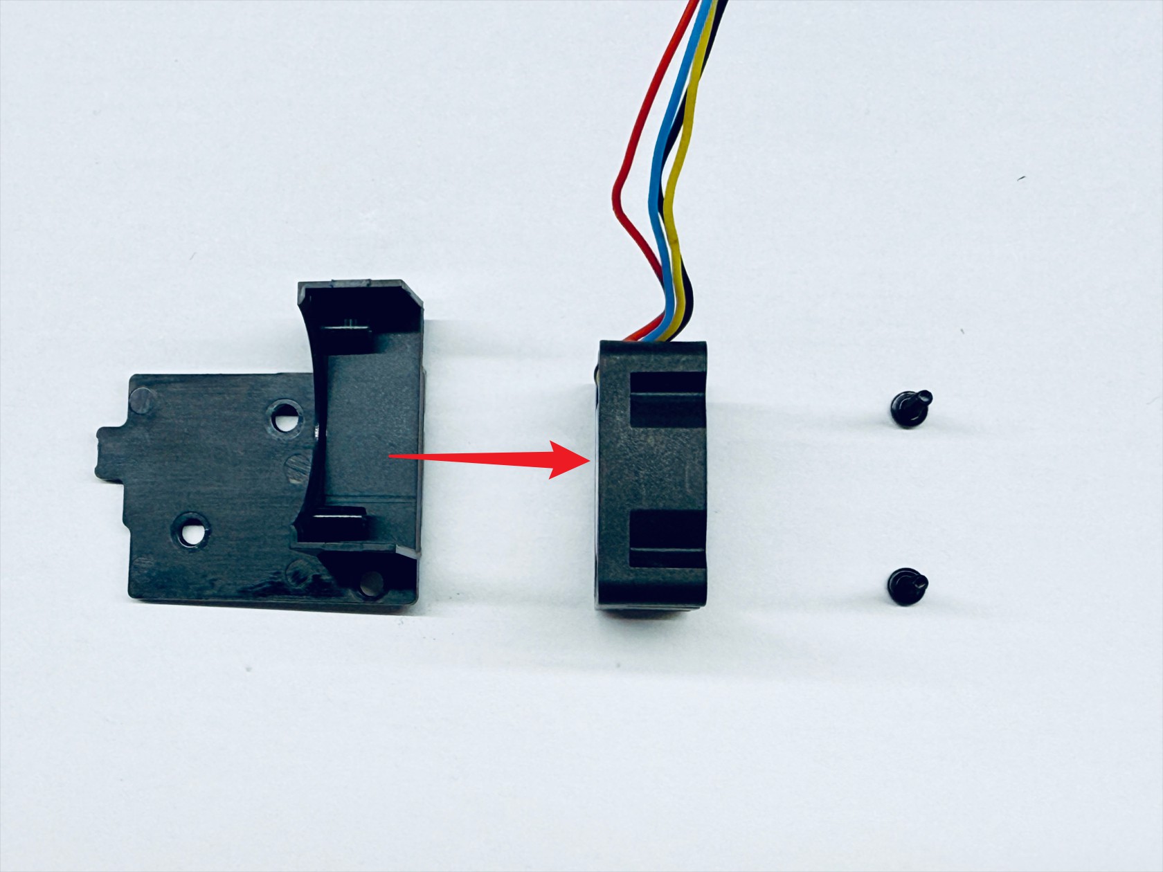
Install the hotend cooling fan onto the fan base in the orientation shown (pay attention to the fan cable direction), and use an H1.5 hex key to tighten the 2 fixing screws
-
Mount the hotend cooling assembly back onto the toolhead male mount, and use an H1.5 hex key to tighten the 3 fixing screws
¶ Step 3. Assemble the hotend
-
Install the ceramic heater
-
Install the thermistor (the probe tip needs to be bent 90°)
-
Install the ceramic heater retaining spring in place

-
Install the cable holder, paying attention to orientation
-
Install the hotend silicone sock, ensuring the notched side faces the same direction as the cable holder
-
Mount the hotend back onto the toolhead male mount, and use an H2.0 hex key to tighten the 2 fixing screws
¶ Step 4. Install the toolhead control board
-
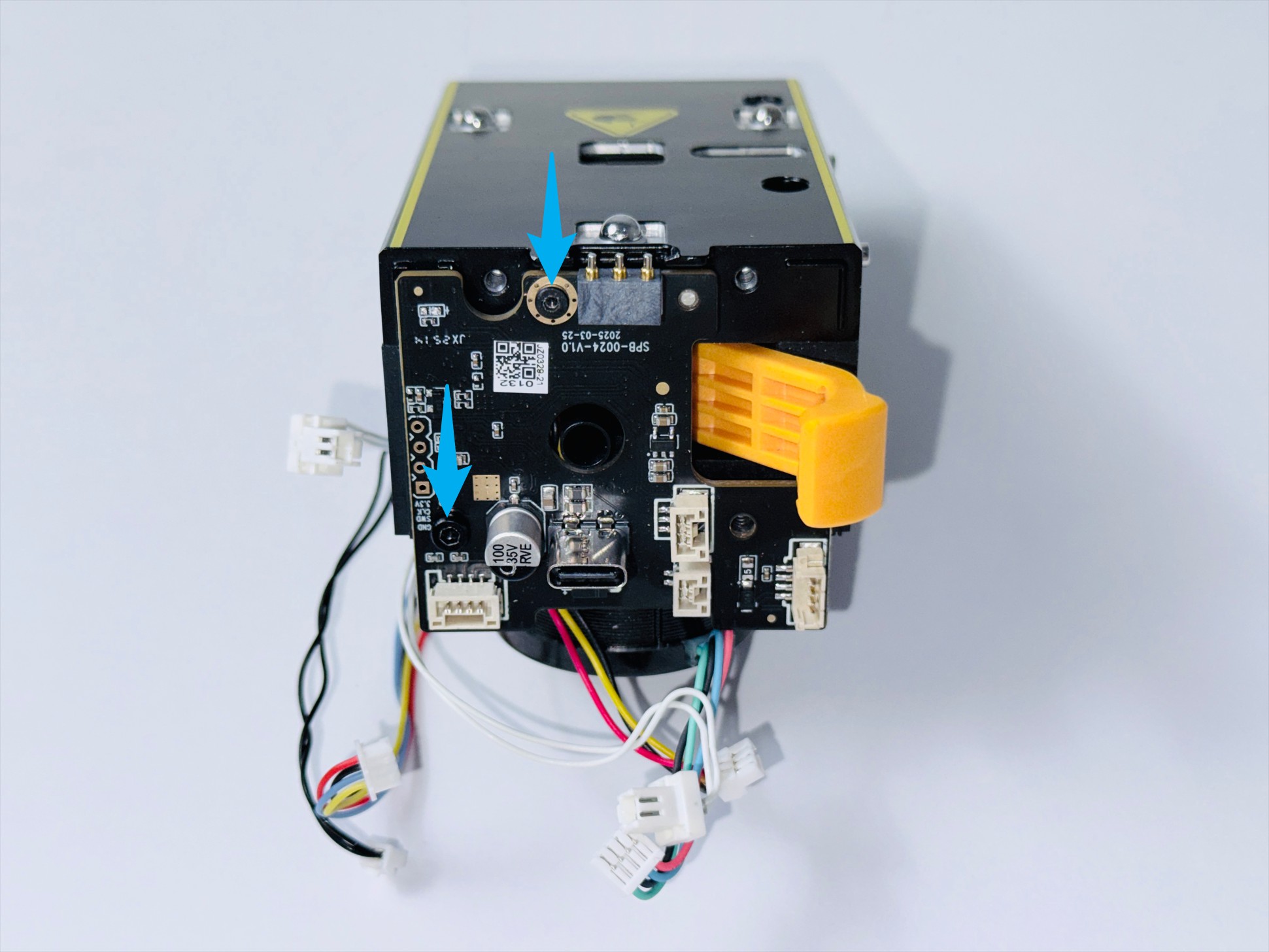
Route the filament runout sensor cable as shown, install the toolhead control board, and use H1.5 & H2.0 hex keys to tighten screws 1 and 2
-
Reconnect all toolhead control board cables
NO. Name 1 Extruder motor cable 2 Filament runout sensor cable 3 Calibration sensor cable 4 Hotend cooling fan cable 5 Ceramic heater cable 6 Thermistor cable Toolhead control board wiring guide(1/3)
Toolhead control board wiring guide(2/3)
Toolhead control board wiring guide(3/3)
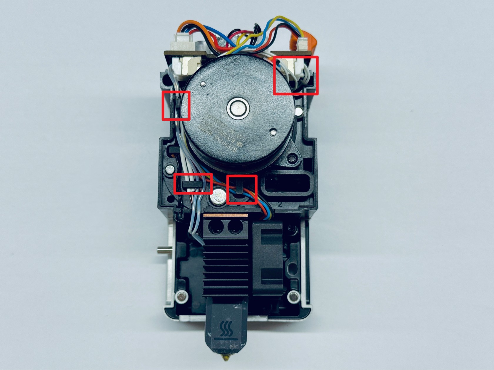
¶ Step 5. Cable management
- Route the cables as shown
¶ Step 6. Install the cover
- Install the toolhead rear cover and top cover, and use the H2.0 hex key to tighten the three top cover screws (screw 3 has a different specification from screws 1 and 2, please take note)
¶ Reach out to Snapmaker Support
After following the troubleshooting steps, if you find it difficult to resolve your issue, kindly submit a support ticket through https://snapmaker.formcrafts.com/u1-troubleshooting-request and share your troubleshooting results with some pictures/videos.
Our dedicated support team will be more than willing to assist you in resolving the issue.