¶ 💡 Compatibility
This guide applies to the following device. Please note when referencing:
- Machine model: U1
¶ ⏰ When to Use This Guide
- The screen reports an error message: "System Failed to Start. No toolhead detected."
- The screen displays an error code: 0003-0522-0100-0006
¶ 📋 Quick Info Card
- Difficulty: ⭐⭐⭐☆☆ (Medium)
- Estimated Time: 10–30 minutes
- Required Skills: Basic cable inspection skills
¶ 🔧 Preparation
¶ Tools Needed
- H2.0 hex key
- Multimeter (if available and you know how to use it)
¶ ⚠️ Important Notes
- Always power off the machine before performing inspections or reconnecting cables.
- Using incorrect screw specifications or over-tightening screws may damage the toolhead PCB.
¶ 🔍 Quick Diagnosis
When powered on, can you observe the internal indicator light through the gap here on the toolhead?
- Toolhead indicator lights are off → Go to Scenario 1
- Toolhead indicator lights are on → Go to Scenario 2
¶ 🛠️ Troubleshooting Steps
¶ Scenario 1: Toolhead indicator lights are off
¶ Cause 1. Damaged capacitor on the toolhead circuit board
-
Use an H2.0 hex key to remove the three screws, then take off the top covers for all four toolheads.
-
Check whether the capacitor is damaged.
- The left image shows a damaged capacitor;
- The right image shows a normal one.
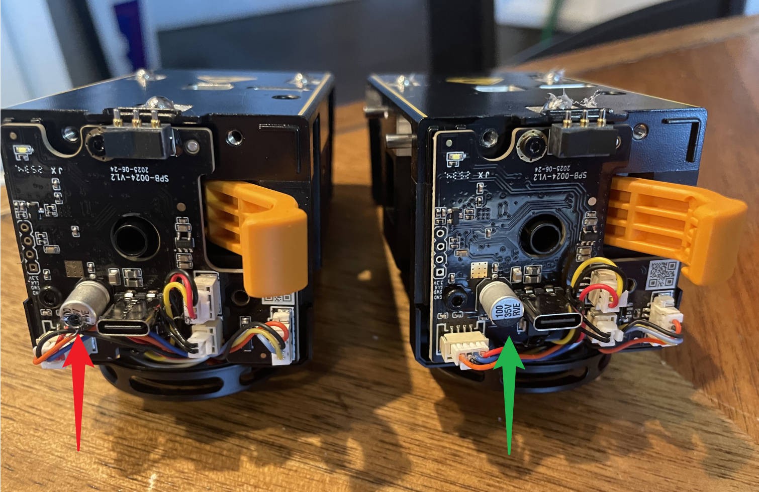
If the capacitor is confirmed to be damaged, please take a photo for record and contact technical support for a replacement part.
U1 Video Guide: Toolhead Cable Replacement
U1 Video Guide: Toolhead PCB Replacement
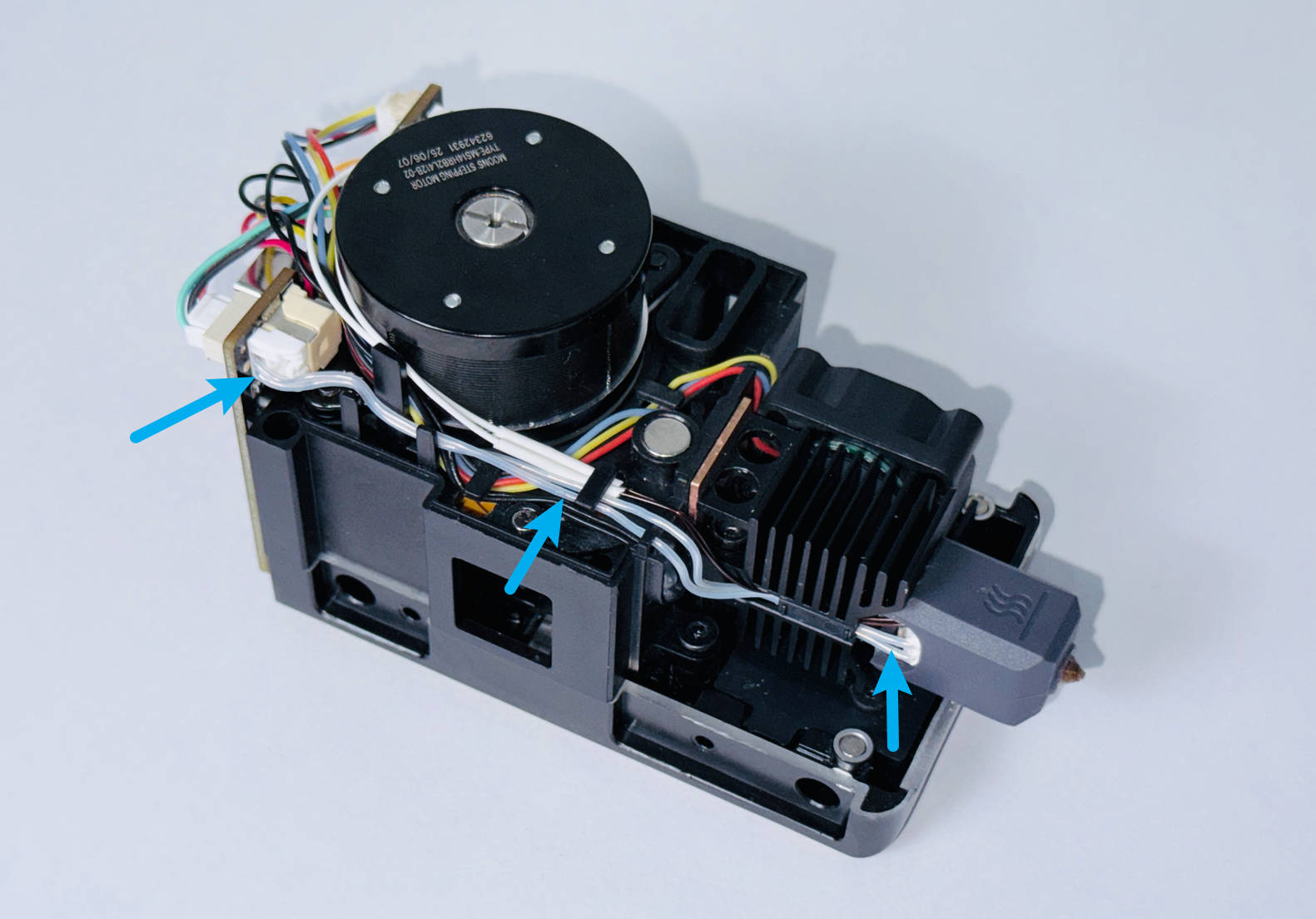
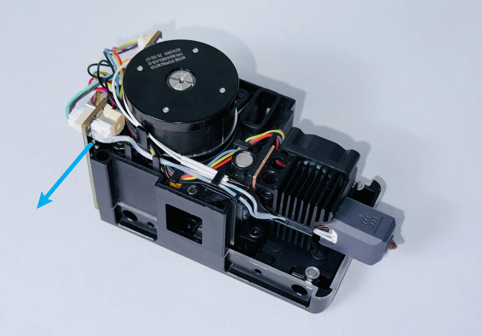
¶ Cause 2. Damaged ceramic heater cable
-
Disconnect the ceramic heater cables from all toolheads. Reconnect all toolhead USB cables, and power on the machine.
-
If the error still occurs, proceed to Cause 3 for further troubleshooting.
-
If the error disappears, identify the specific location and number of damaged cables.
-
Visually inspect the insulation of the ceramic heater cables for any damage.
-
Connect the ceramic heater of only one toolhead at a time while keeping the other three disconnected. Restart the machine each time. If the error appears, it indicates that the ceramic heater of that toolhead is short-circuited.
If the ceramic heater is confirmed to be damaged, please contact technical support for a replacement part.
U1 Video Guide: Ceramic Heater & NTC Thermistor Replacement
¶ Cause 3. Faulty toolhead USB cable
-
The toolhead USB cable connects to the toolhead on the one end, and the machine on the other. Power off the machine and disconnect the end of all USB cables that connect to the machine.
-
Connect only one USB cable at a time, keeping the other three disconnected. Restart the machine. Under normal conditions, the internal light of the connected toolhead will blink on and off periodically.
If the toolhead USB cable does not behave as described above, record the staus of the indicator light, and contact technical support for a replacement part.
U1 Video Guide: Toolhead Cable Replacement
¶ Cause 4. Abnormal HUB board power supply
Please refer to U1 Video Guide: How to Remove the Side Panels to remove the machine’s right side panel.
-
Keep the top panel and right side panel of the machine uninstalled. Reconnect the toolhead USB cables and power on the machine.
-
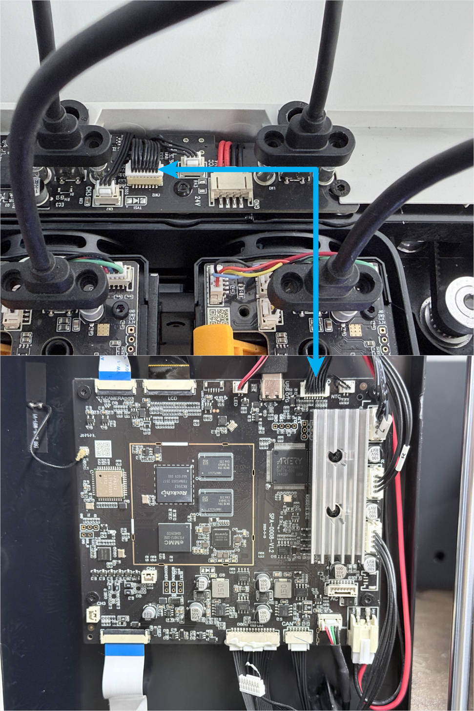
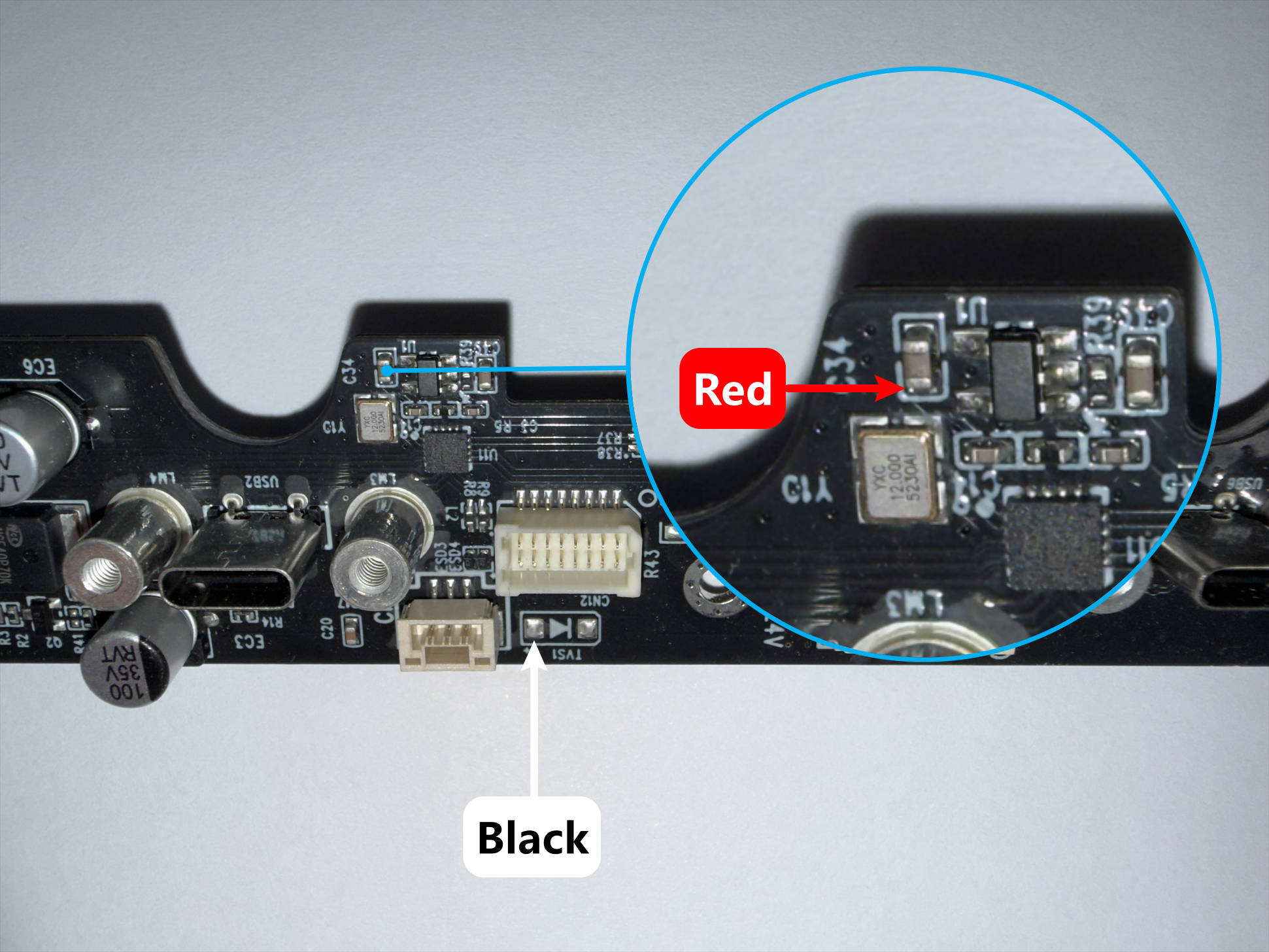
Set a multimeter to DC voltage mode and measure the points as shown in the table below:
| Test Point | Probe Position | Reference Value |
|---|---|---|
| A |
 |
24V |
| B |
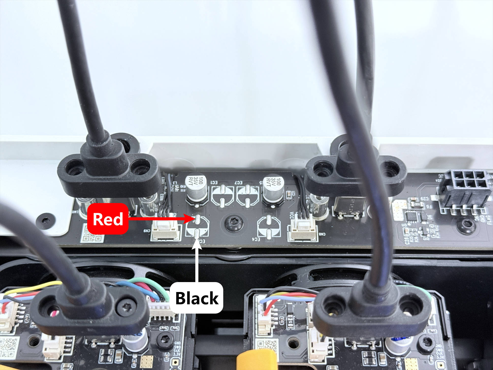 |
24V |
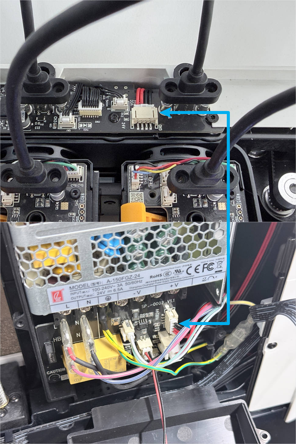
- If your measurement results match the values below, it indicates a poor connection or fault in the HUB board power supply cable.
| Test Point | Reference Value | Results |
|---|---|---|
| A | 24V | 0V |
| B | 24V | 0V |
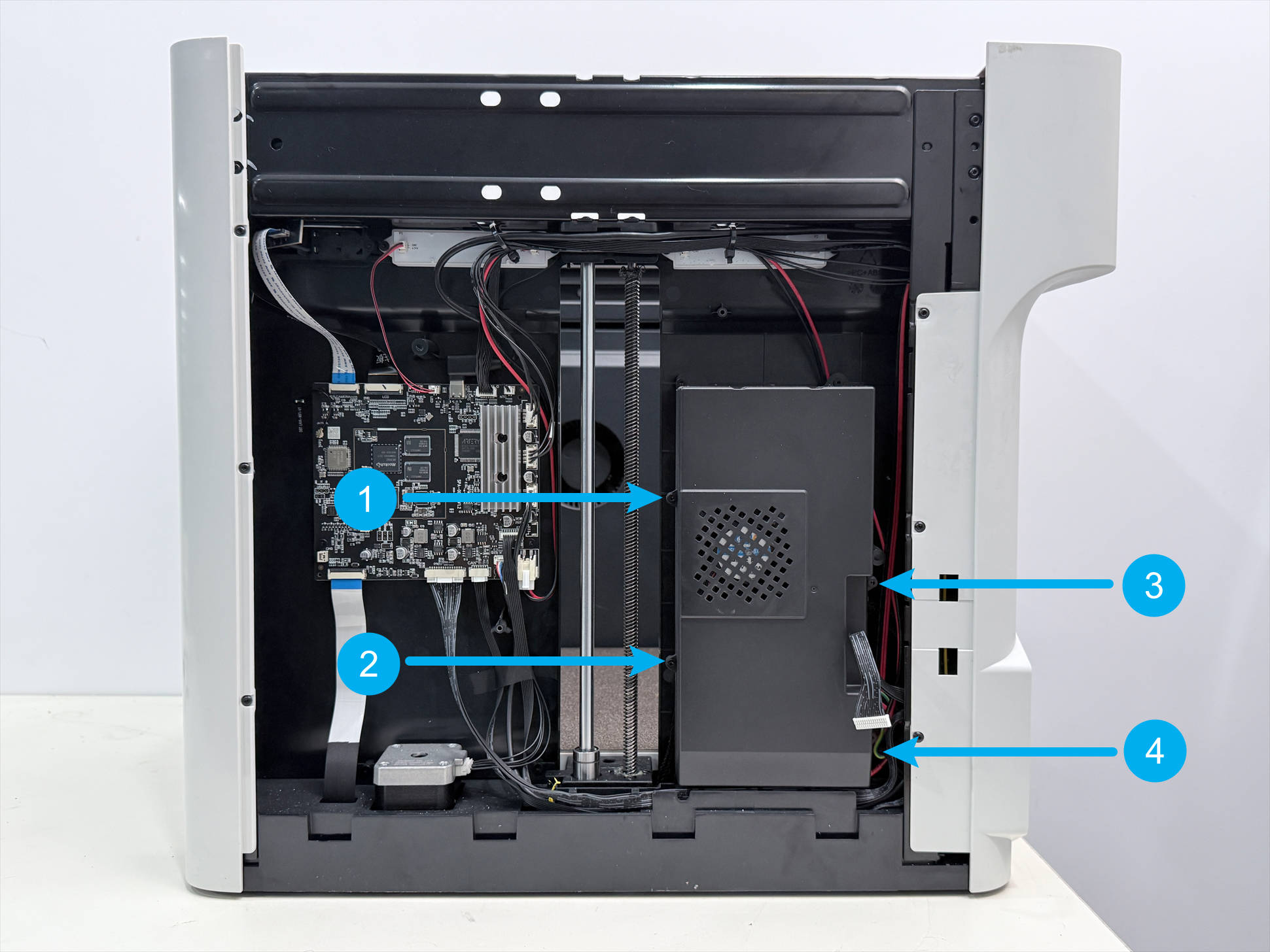
Use an H2.0 hex key to remove the four screws on the cover, then unplug and reconnect both ends of the power supply cable. Check if the issue is resolved.
- If your measurement results match the values below, it indicates a poor connection or fault in the 16-pin cable between the main control board and the HUB board.
| Test Point | Reference Value | Results |
|---|---|---|
| A | 24V | 24V |
| B | 24V | All pins read 0V |
Check if any pins in the mainboard connector are bent, then unplug and reconnect both ends of the 16-pin cable. Check if the issue is resolved.
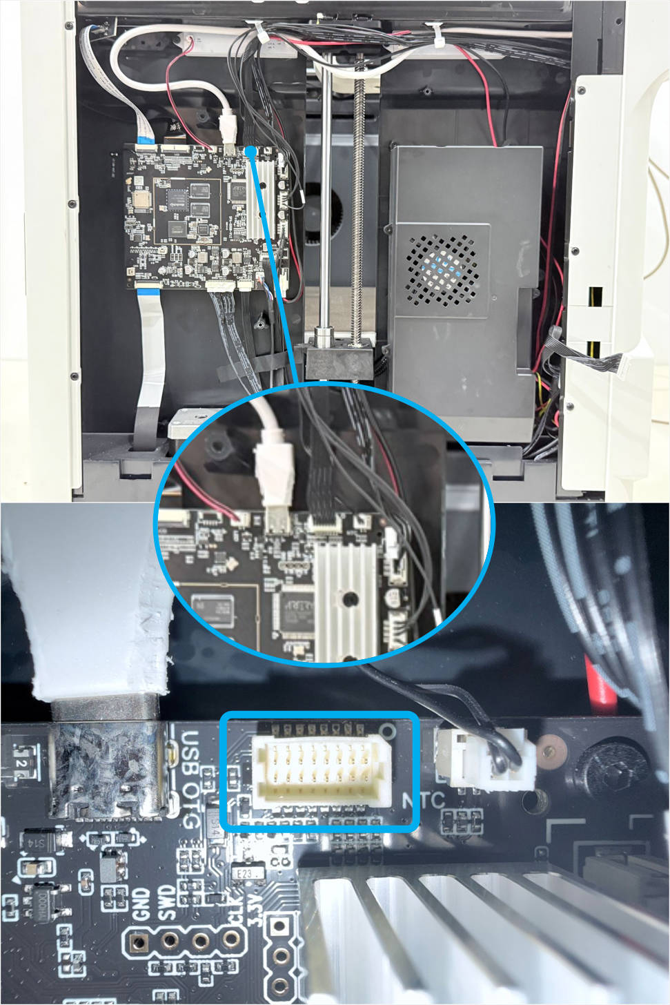
When reconnecting the 16-pin cable, hold the inner panel where the mainboard is mounted with one hand.
Depending on your situation, contact technical support for replacement parts.
¶ Scenario 2: Toolhead indicator lights are on
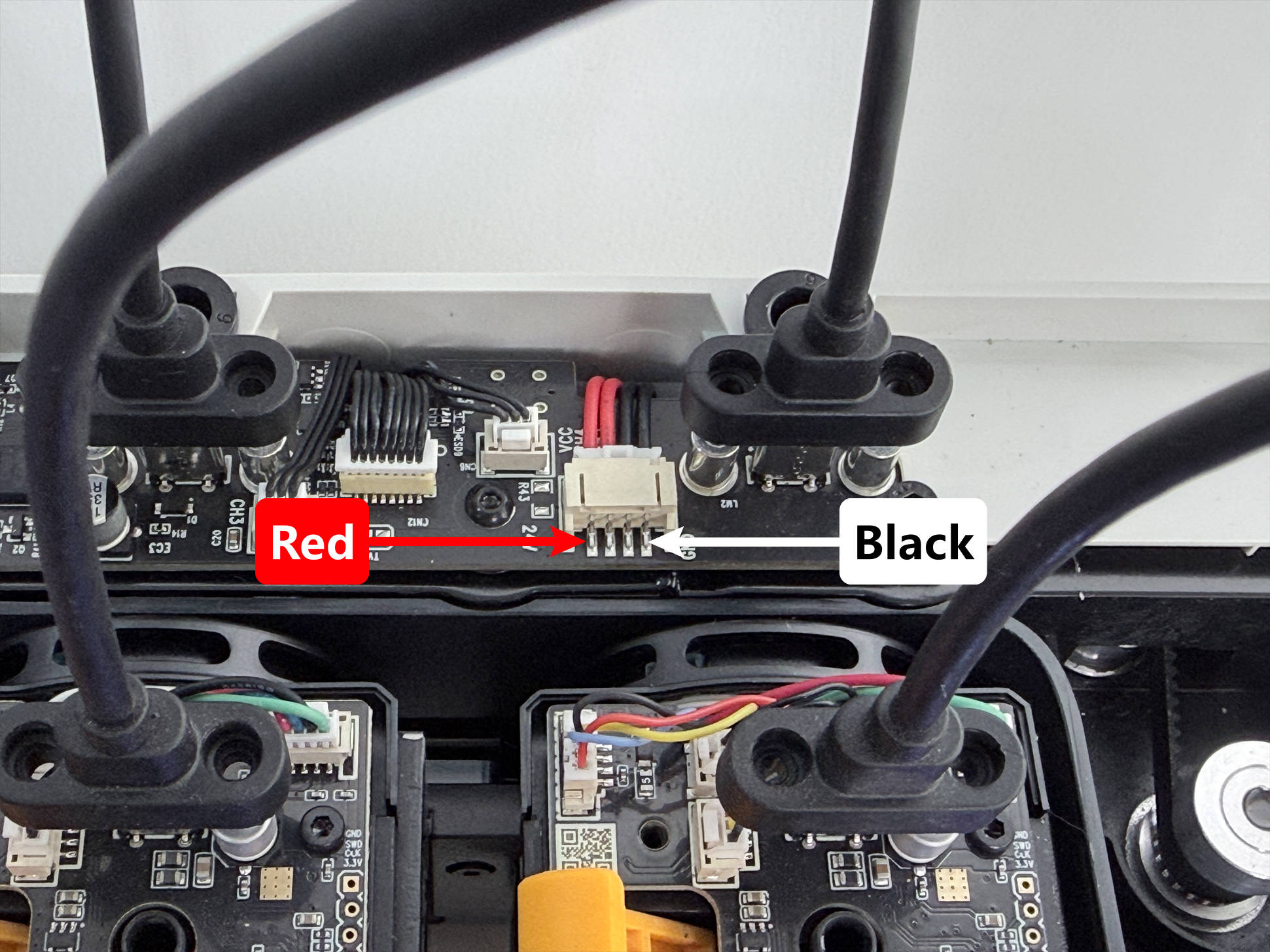
¶ Cause 1. Faulty HUB board
Please refer to U1 Video Guide: How to Remove the Side Panels to remove the machine’s rear cover panel.
-
Keep the top panel and right side panel of the machine uninstalled. Reconnect the toolhead USB cables and power on the machine.
-
Set a multimeter to DC voltage mode and measure the points as shown in the table below.
The disconnected wiring in the image is for illustration of the measurement points only; do not disconnect any cables during actual measurement.
| Test Point | Probe Position | Reference Value | Results |
|---|---|---|---|
| C |
 |
3.3V | |
| D |
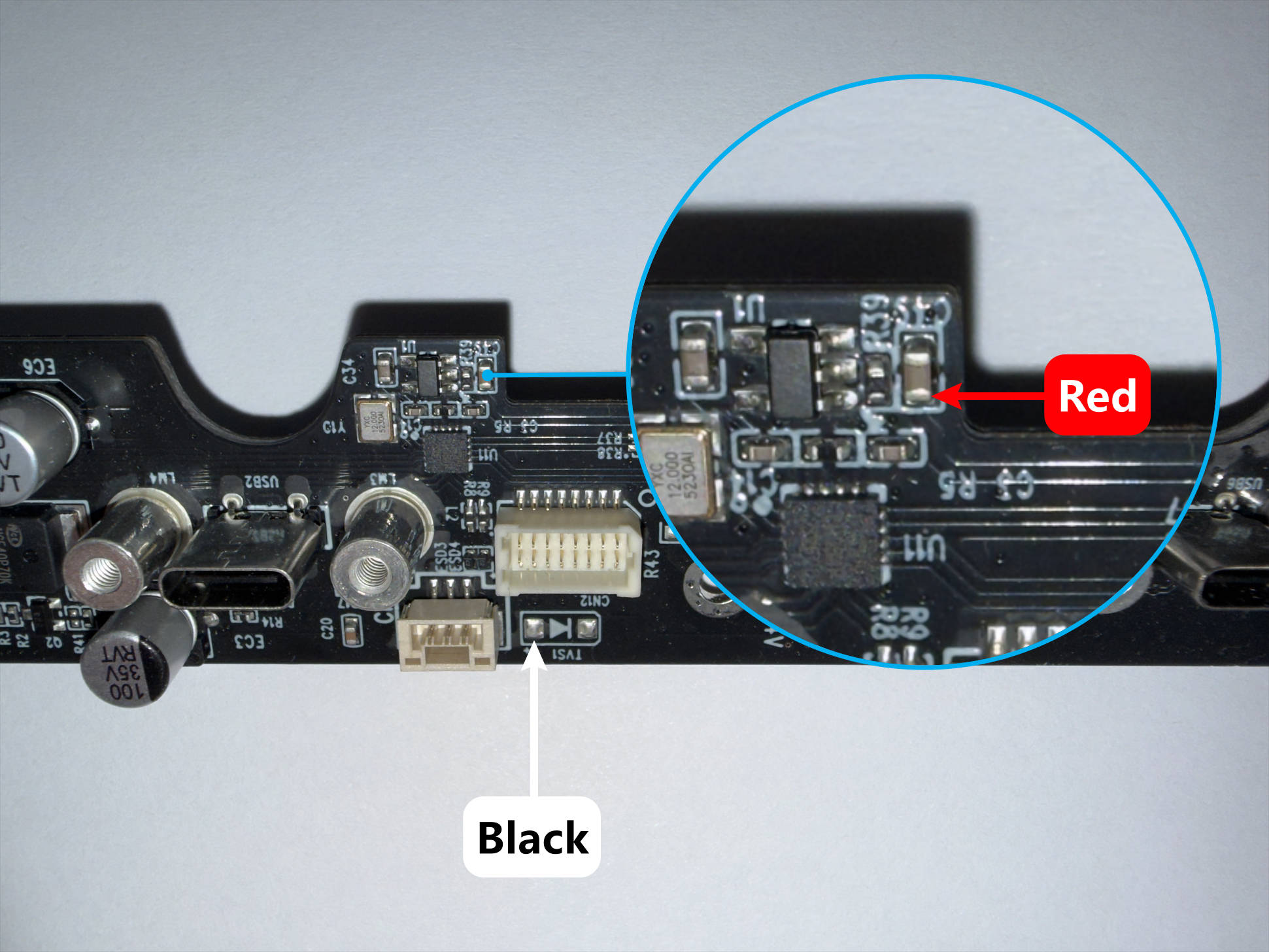 |
5V |
Copy the table above, fill in the Results column, and contact technical support.
¶ Cause 2. Docking sensor wire pinched
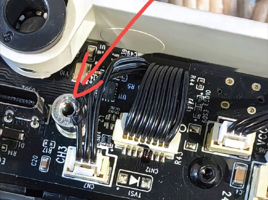
-
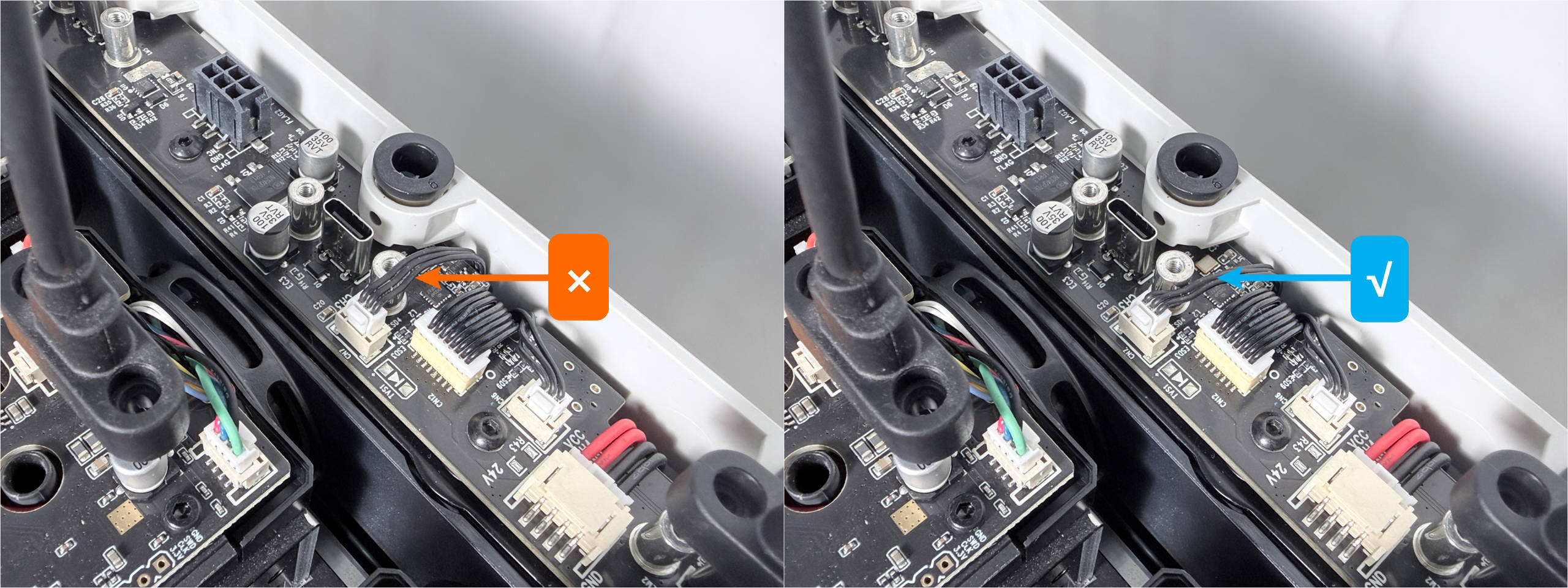
Visually inspect the docking sensor wire for any signs of pinching.
-
Disconnect all docking sensor wires, keep the toolhead USB cables connected, and power on the machine. If the machine starts normally, this indicates that the docking sensor wire is damaged. Please contact technical support for replacement parts.
¶ Cause 3. Faulty Main USB Cable
- The main USB cable connects to the mainboard on the one end and to the bottom of the HUB on the other. Try unplugging and reconnecting both ends to see if the issue is resolved.
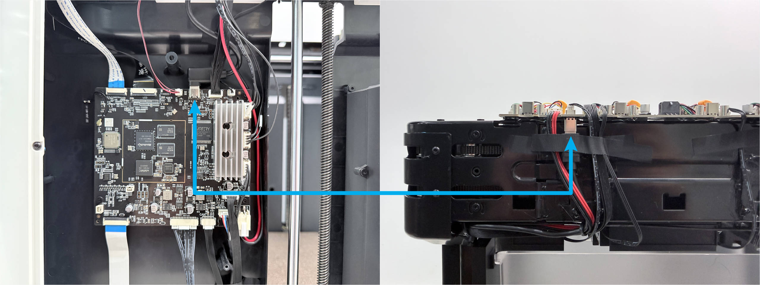
- If you have a spare USB-C to USB-C data cable, you can replace the machine’s main USB cable to verify.
Depending on your situation, contact technical support for replacement parts.
¶ 📚 Related Resources
- U1 Video Guide: Toolhead Cable Replacement
- U1 Video Guide: Toolhead PCB Replacement
- U1 Video Guide: Ceramic Heater & NTC Thermistor Replacement
- U1 Video Guide: How to Remove the Side Panels
¶ 💬 Reach out to Snapmaker Support
After following the troubleshooting steps, if you find it difficult to resolve your issue, kindly submit a support ticket through https://snapmaker.formcrafts.com/u1-troubleshooting-request and share your troubleshooting results with some pictures/videos. Our dedicated support team will be more than willing to assist you in resolving the issue.