¶ Overview
¶ Location
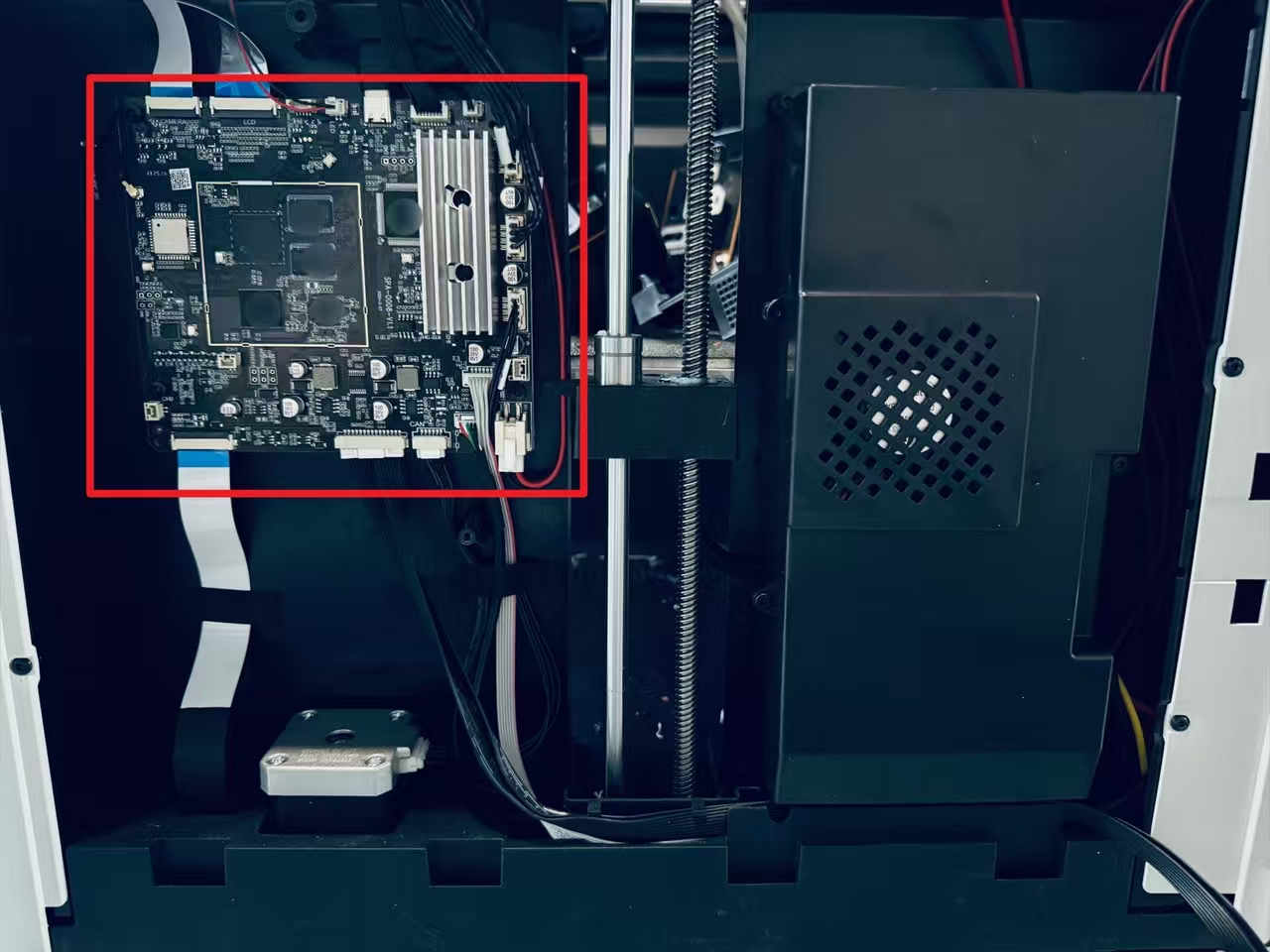
The main control board is located at the right inner panel of the machine, and replacing it requires removing the right panel.
¶ Terminology
Different from our official term, some people may use the following terms to describe this component:
- Motherboard
- mainboard
- Brain board
- Controller
- Printer control board
¶ Difficulty and Time Estimate
- Difficulty:★★★☆☆ (moderate)
- Estimated Time:20 minutes
¶ Where to Buy
US: https://us.snapmaker.com/products/main-control-board-for-snapmaker-u1
EU: https://eu.snapmaker.com/products/main-control-board-for-snapmaker-u1
Global: https://shop.snapmaker.com/products/main-control-board-for-snapmaker-u1
¶ Tools and Parts Required
- H2.0 hex key
- New main control board
¶ Before You Start
After replacing the main control board, the machine will use the default toolhead swapping coordinates built into the new board. In rare cases, this may cause a toolhead swapping anomaly. Therefore, we recommend backing up the toolhead swapping coordinates from the original control board before replacement. If a swapping issue occurs later, you can refer to this backup and restore the original coordinate data.
Additionally, if there is any homing_calibrated_origin data available, you may back it up as well. If this data does not exist, it can be safely ignored.
Please follow the steps below for detailed instructions.
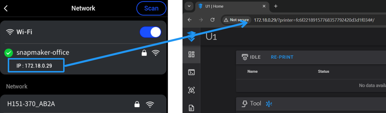
(1) Check the machine IP in Settings > Wi-Fi, then enter the IP address in your computer browser.
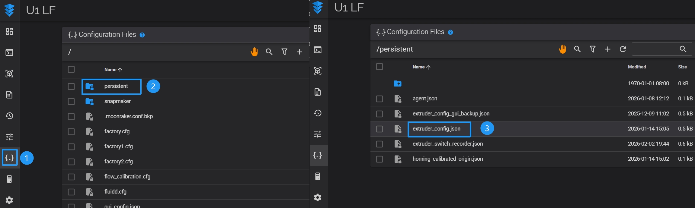
(2) On the Fluidd page, click Configuration, then go to the persistent folder and download the extruder_config.json file and the homing_calibrated_origin.json file (if available).
¶ Part 1. Remove the panels
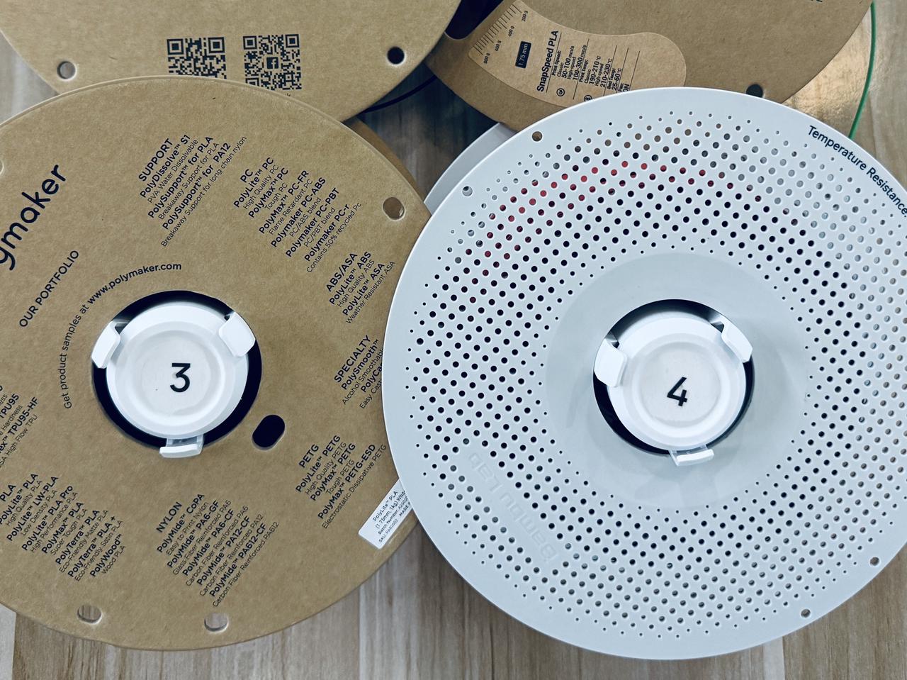
¶ Step 1. Unload filament from toolheads 3 and 4
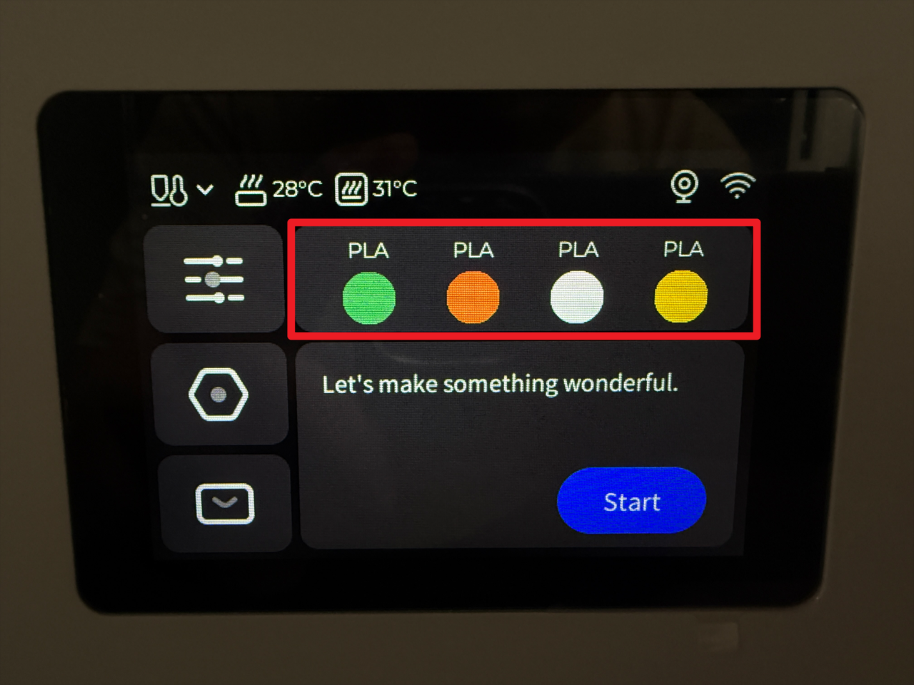
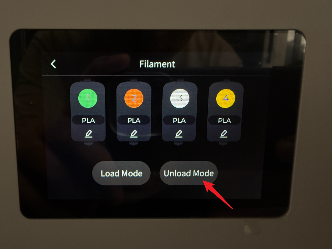
- Tap the highlighted area on the screen.
- Tap "Unload Mode".
- Select toolheads 3 and 4, then tap "Unload".
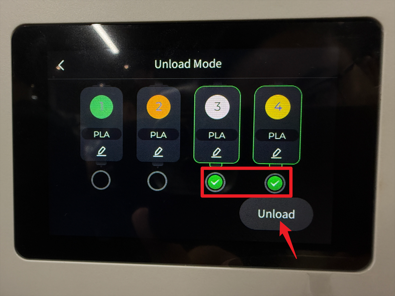
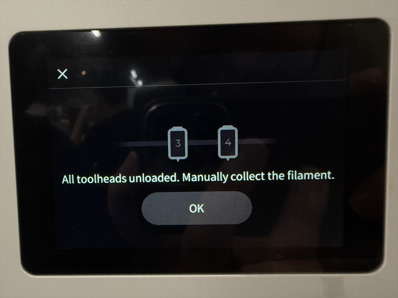
- Wait for the machine to complete the unloading.
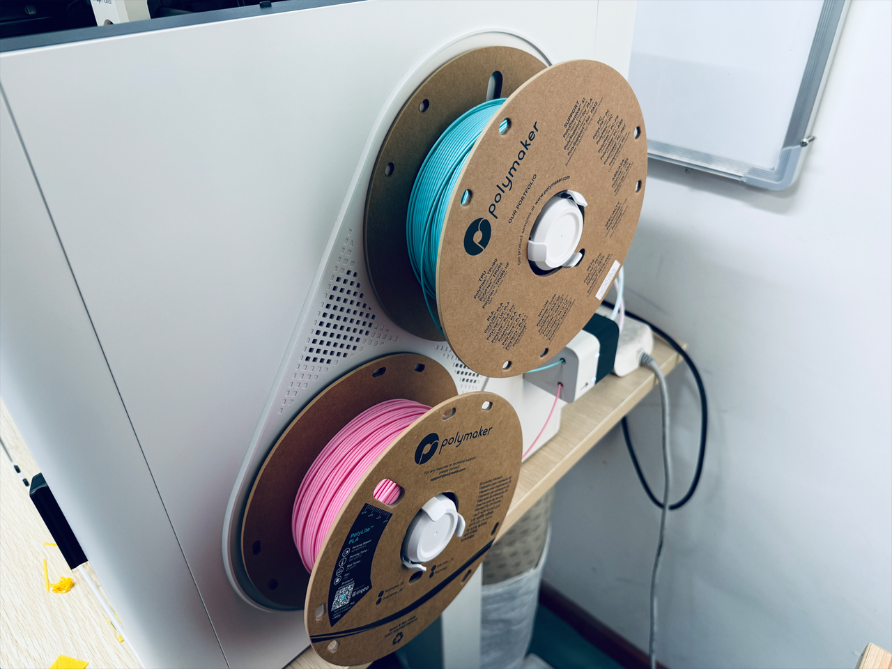
- Turn the spool to retract the remaining filament.
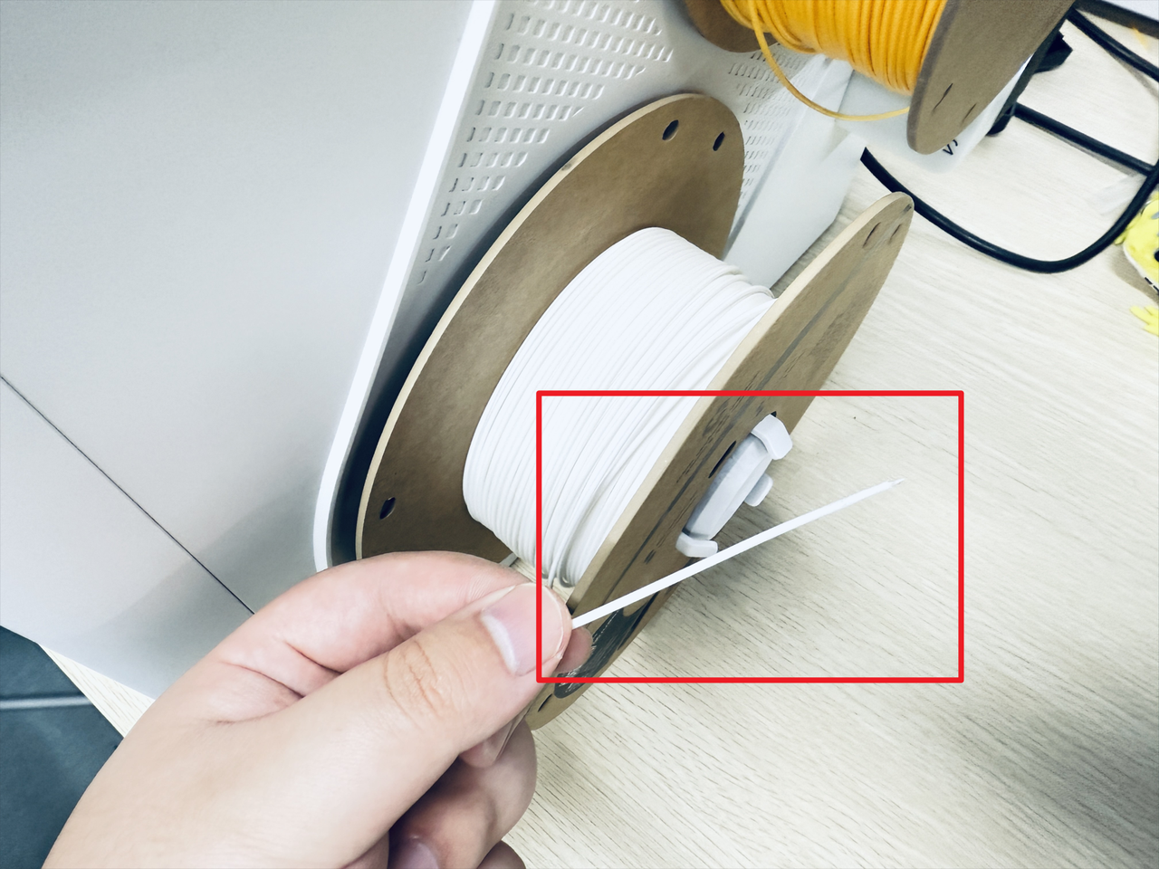
- Remove the spools and spool holders 3 and 4.
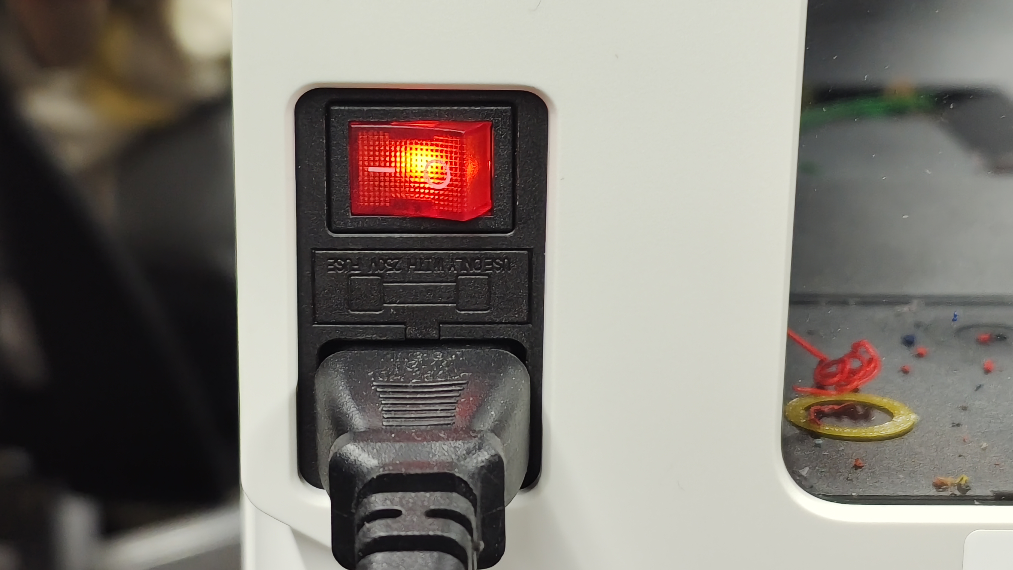
¶ Step 2. Power off the machine
- Before proceeding, please turn off the machine and unplug the power cable!

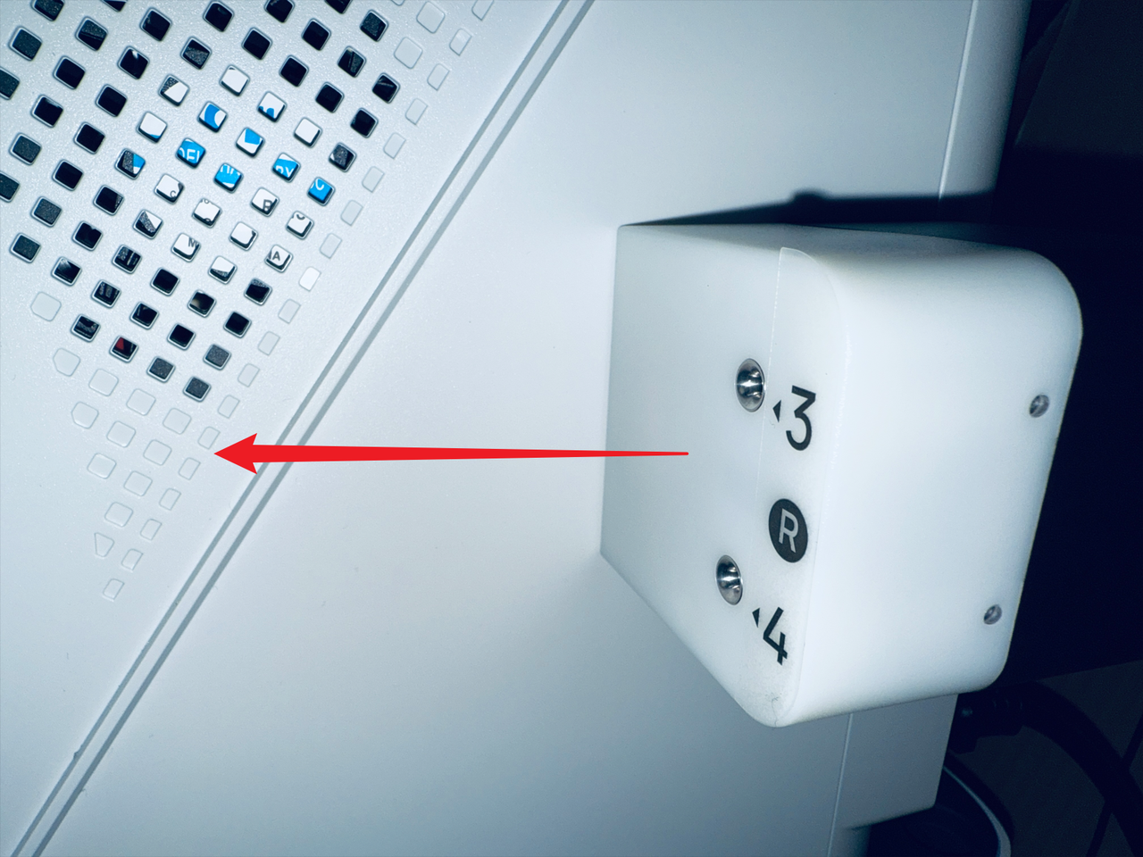
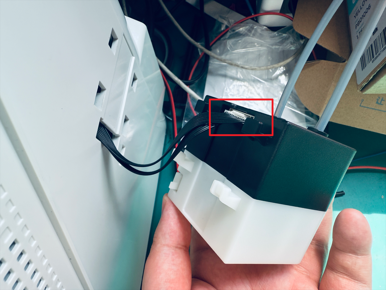
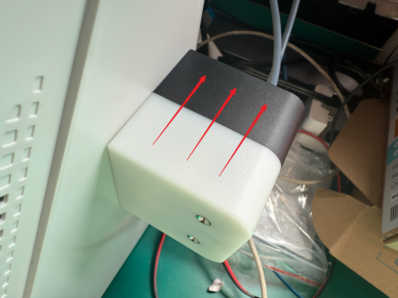
¶ Step 3. Remove the filament feeder on right side
- Press the clip at the marked location.
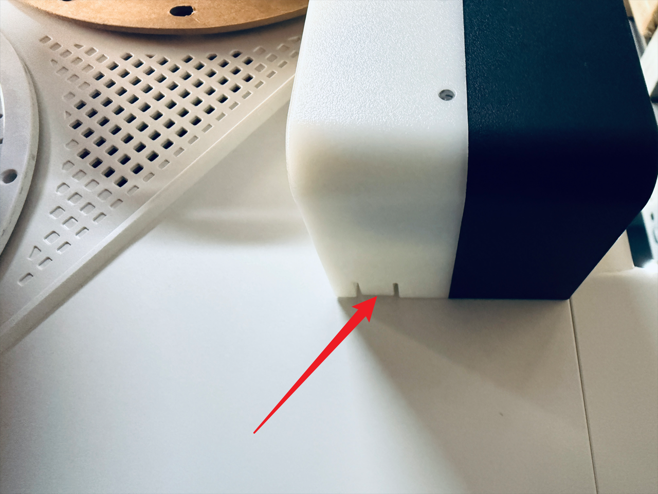
- While pressing the clip, slide the filament feeder in the indicated direction to remove it.
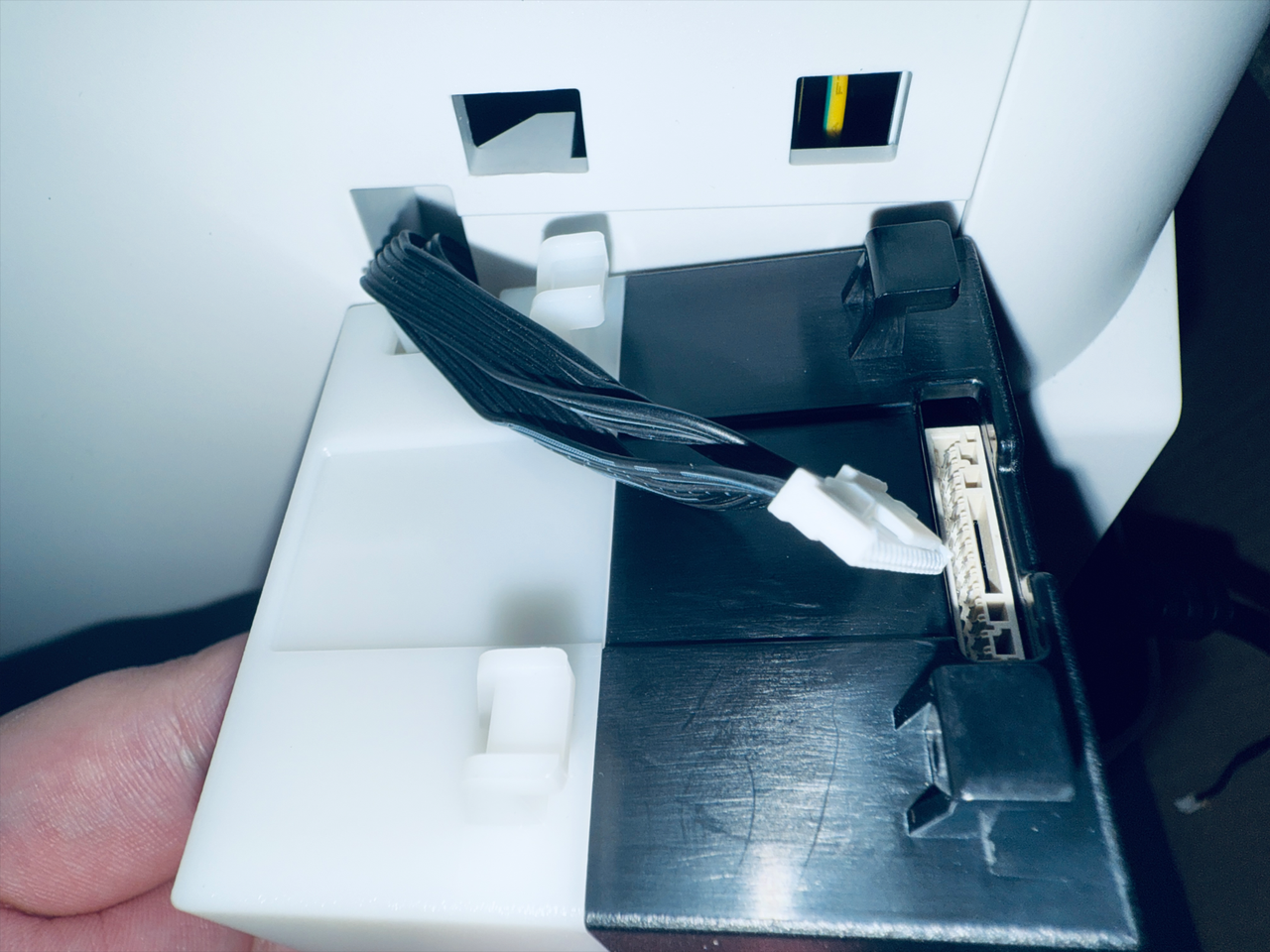
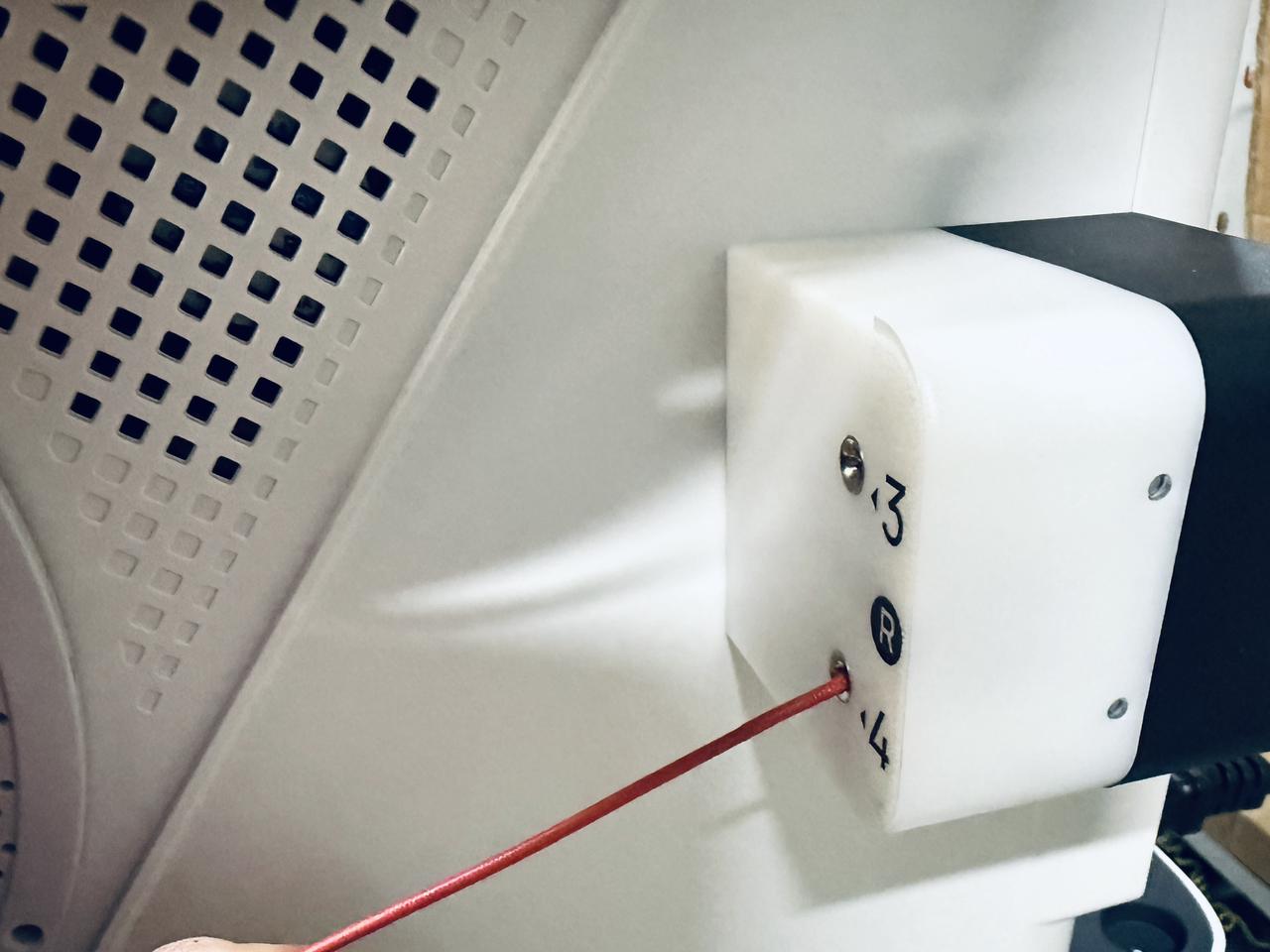
- Next, press point 1 as shown in the image to disconnect the filament feeder cable.
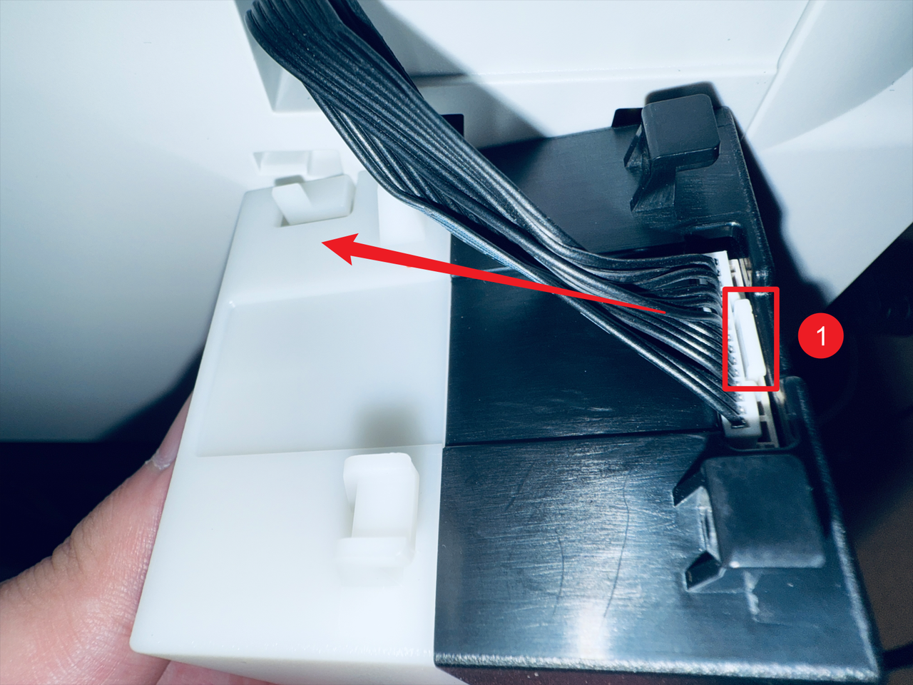
- Complete.
¶ Step 4. Disconnect USB cables
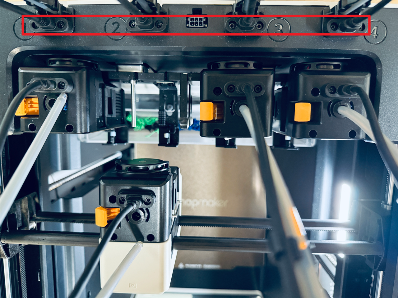
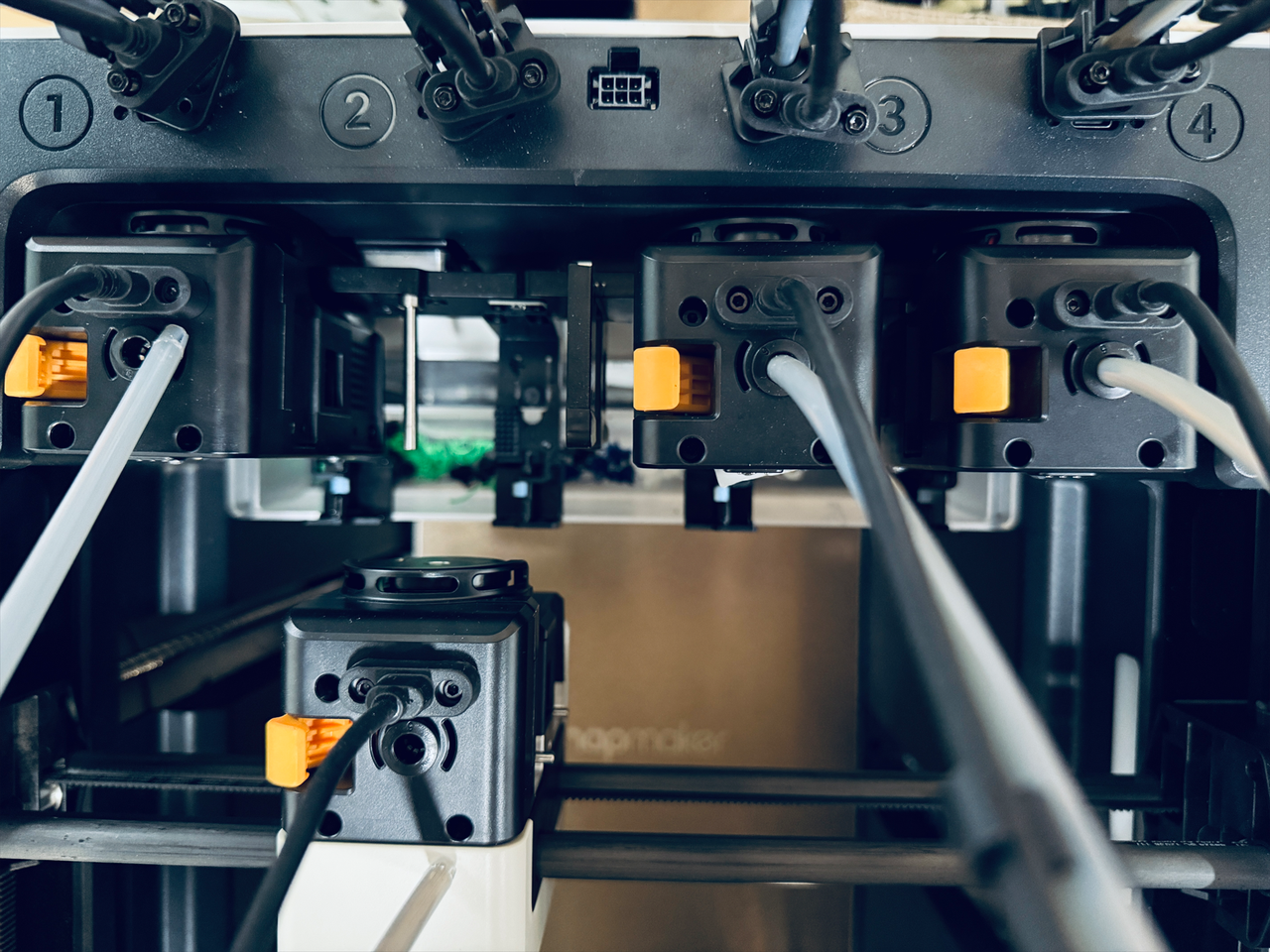
- Use a H2.0 hex key to remove the 8 screws from the 4 USB cables, then unplug the cables.
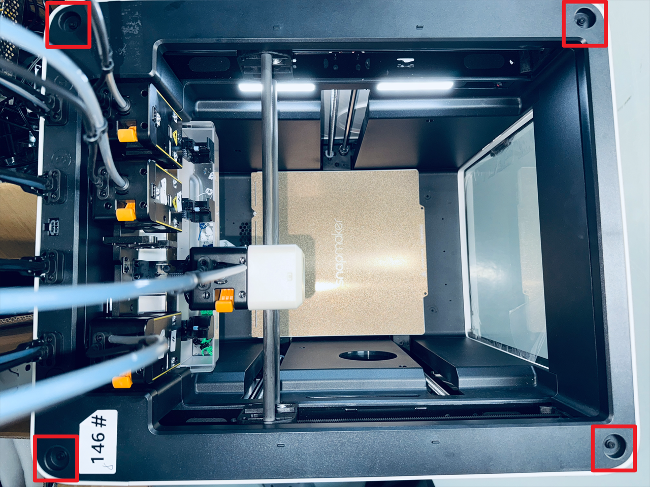
¶ Step 5. Remove the top cover panel
- Take out the silicone plugs from all four corners of the top cover panel.
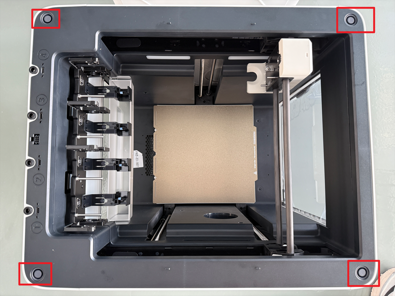
- Use a H2.0 hex key to remove the 4 screws beneath the plugs.
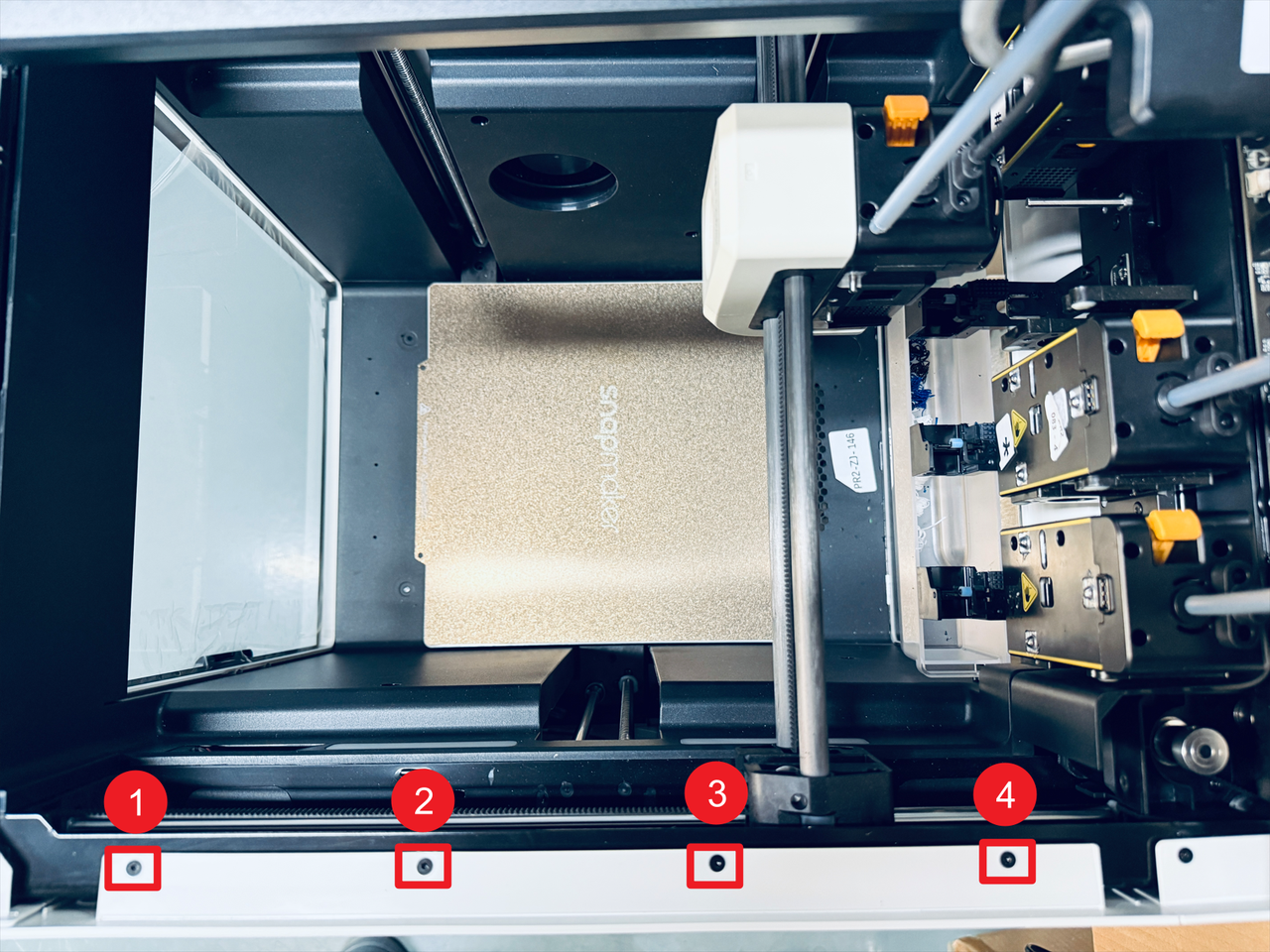
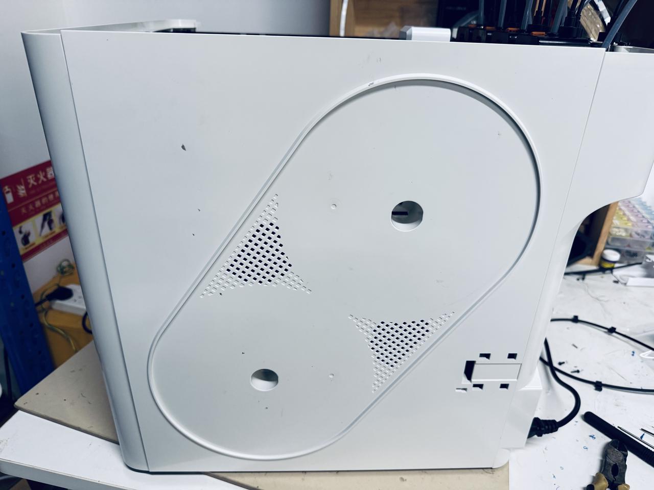
¶ Step 6. Remove the right panel
- Slightly shift the top cover panel as shown in the image, then remove the four marked screws.
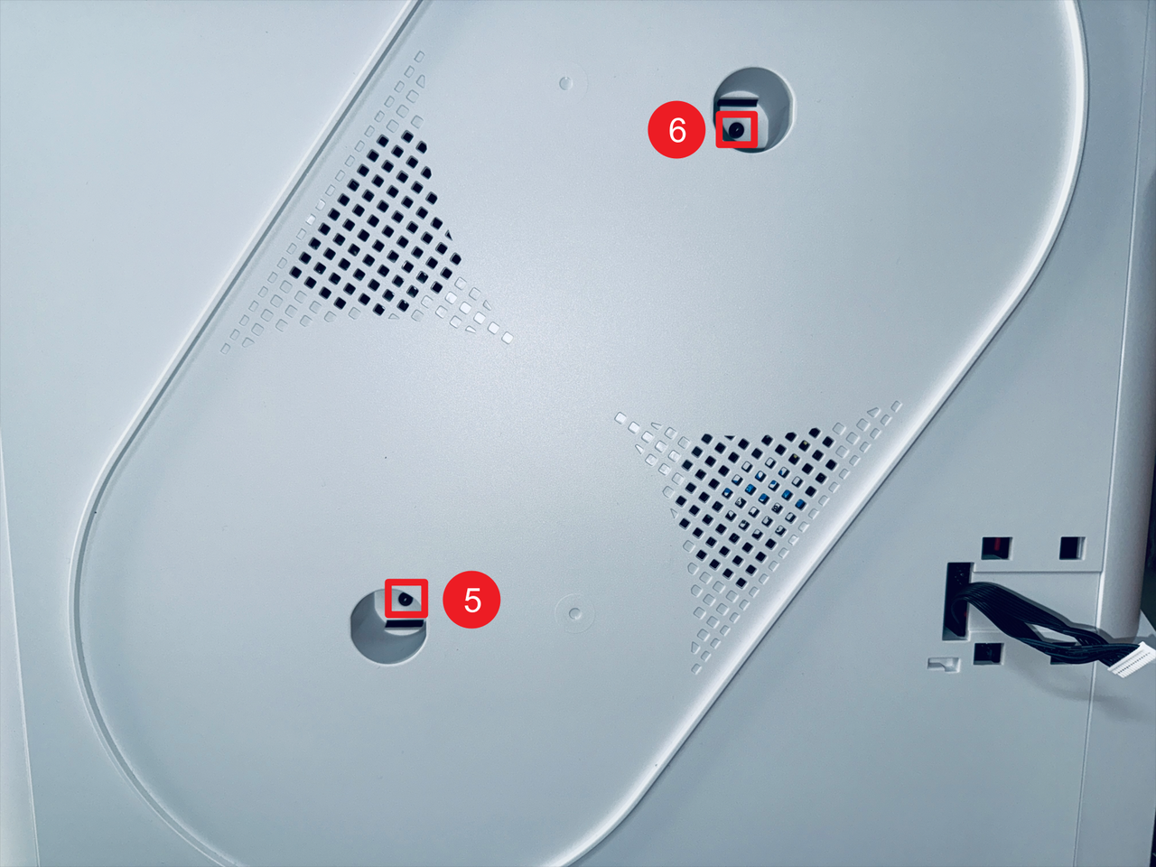
- Remove screws 5 and 6 located inside the spool holder holes.
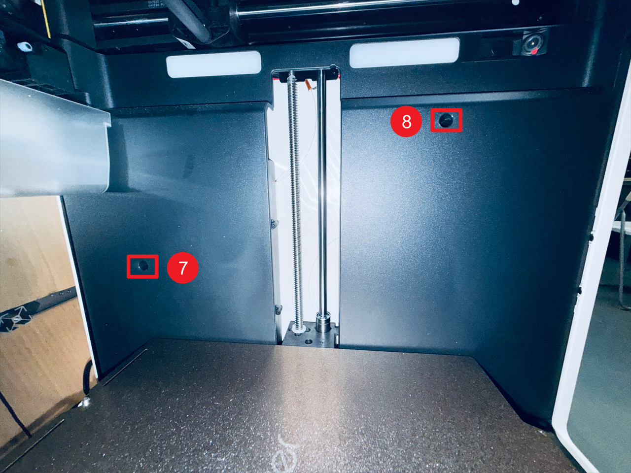
- Then remove screws 7 and 8 on the right inner panel.
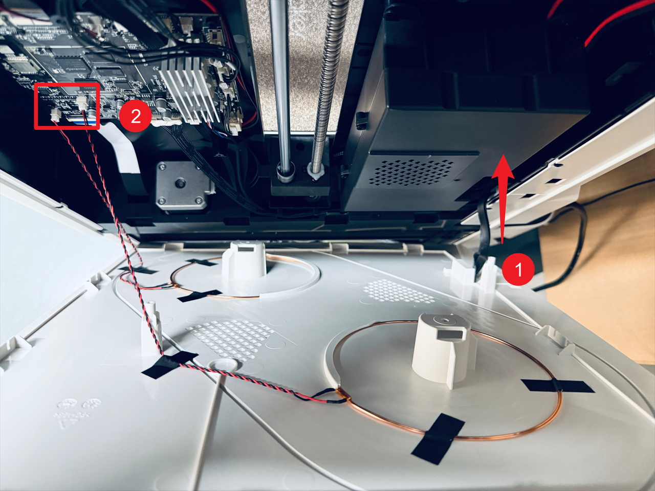
- Pass the filament feeder cable through position 1 and disconnect the two RFID cables at position 2, then remove the right panel.
¶ Part 2. Replace the main control board
¶ Step 7. Remove the old main control board
- Disconncet the 16 cables from main control board.
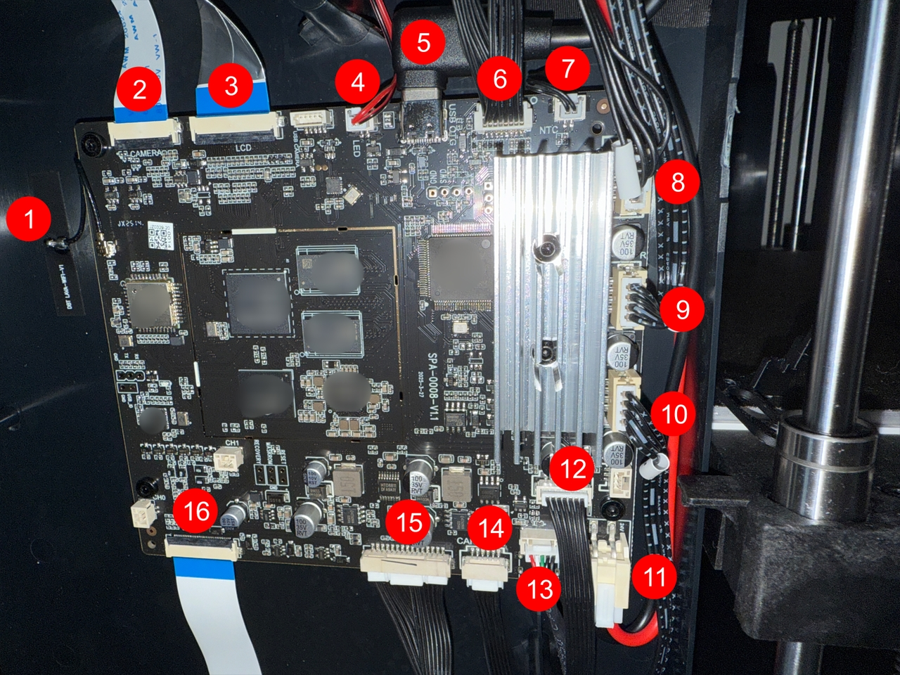
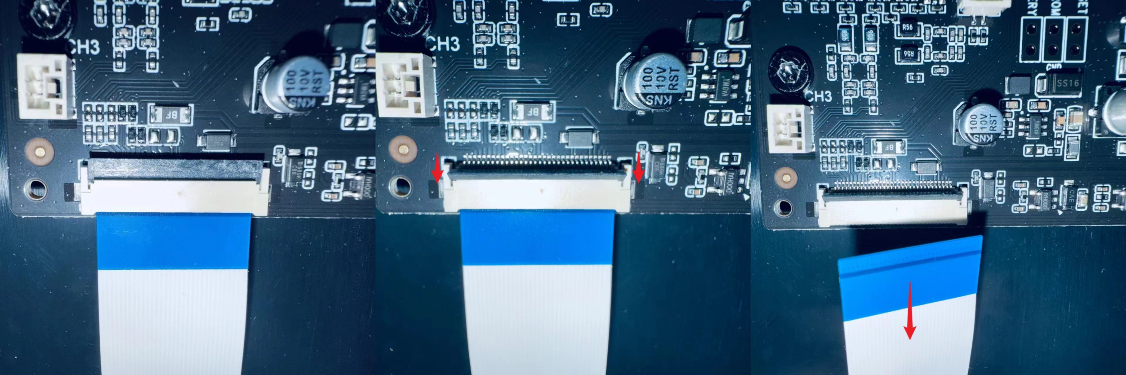
For the FFC cables at positions 2, 3, and 16, lift the black flip cover slowly before removing them.
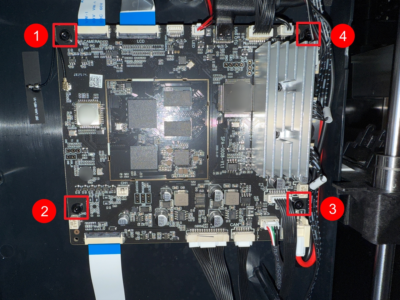
- Use the H2.0 hex key to unscrew the 4 screws, then remove the old main control board.
¶ Step 8. Install the new main control board
- Install the new main control board, use the H2.0 hex key to tighten the 4 screws.
- Reconnect the cables to the main control board.

| No. | Cable | No. | Cable |
|---|---|---|---|
| 1 | LAVA WIFI Antenna | 9 | Right Motor Cable |
| 2 | Camera Control Cable | 10 | Z-axis Motor Cable |
| 3 | Screen Control Cable | 11 | Main Board Power Cable |
| 4 | Light Strip Control Cable | 12 | Heated Bed Control Cable |
| 5 | USB Transfer Cable | 13 | USB Expansion Cable |
| 6 | Main Control Board—HUB Board Connection Cable | 14 | CAN Board Expansion Cable |
| 7 | Chamber Temperature NTC | 15 | Filament Feeder Cable |
| 8 | Left Motor Cable | 16 | RFID Transfer Cable |
¶ Part 3. Reassemble the machine
¶ Step 9. Reinstall the right panel
- Reconnect the RFID cables at position 1, pass the filament feeder cable through position 2, then install the right panel.

- Use the H2.0 hex key to tighten the 8 screws of the right panel.
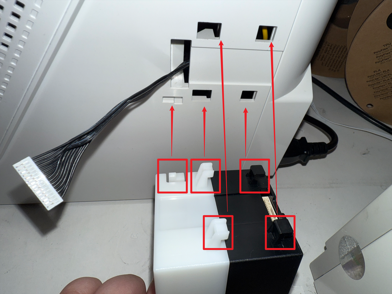
¶ Step 10. Reinstall filament feeder and spools
- Reconnect the filament feeder cable and organize it as shown.
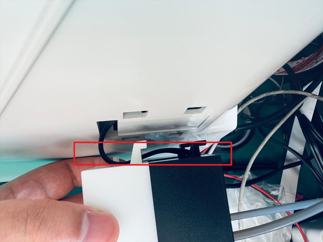
- Align the feeder clips with the corresponding positions, then push the feeder into place in the direction shown to complete installment.
- Reinstall the spools and spool holders.
¶ Step 11. Reinstall the top cover panel
- Install the top cover panel, use the H2.0 hex key to tighten the 4 screws.
- Install the silicone plugs.
¶ Step 12. Reconnect USB cables
- Reconnect the USB cables, then use the H2.0 hex key to tighten the 8 screws.
¶ Step 13. Insert filament
- Power on the machine and insert the filaments into the corresponding feeder ports in sequence.
¶ Reach out to Snapmaker Support
After following the troubleshooting steps, if you find it difficult to resolve your issue, kindly submit a support ticket through https://snapmaker.formcrafts.com/u1-troubleshooting-request and share your troubleshooting results with some pictures/videos.
Our dedicated support team will be more than willing to assist you in resolving the issue.