¶ 📍Overview
¶ Safety Instructions
⚠ Caution:
-
Before performing any maintenance or troubleshooting, please ensure that the printer is powered off and the power cable is unplugged to avoid short circuits or damage to the device.
-
Before operating, please confirm that the hot end and heated bed temperatures have dropped to a safe range to prevent burns.
-
If operation under high-temperature conditions is required, please make sure to wear heat-resistant gloves and take appropriate protective measures.
-
If you have any questions, please submit a support ticket through the Snapmaker App, and we will provide assistance as soon as possible.
¶ Quick Info Card
- Difficulty: ⭐⭐⭐☆☆ (Medium)
- Estimated Time: 80 minutes
¶ Before You Start
¶ Location
¶ Terminology
Apart from our official terminology "Heated Bed", you may also see the following terms used to refer to this component:
-
Build Plate
-
Build Platform
-
Print Bed
¶ Availability
You can purchase a spare part from the following channels:
¶ Tools Needed
- New heated bed
- H2.0 hex key
- Spool
| File type | Download link |
|---|---|
| STL | Click to download |
| G-code | Click to download (PLA only) |
¶ 🛠️ Procedure
¶ Step 1. Remove the right side panel
Please refer to the first part (0:00–4:28) of the side panel disassembly tutorial to remove the right side panel of the machine.
¶ Step 2. Remove the heated bed
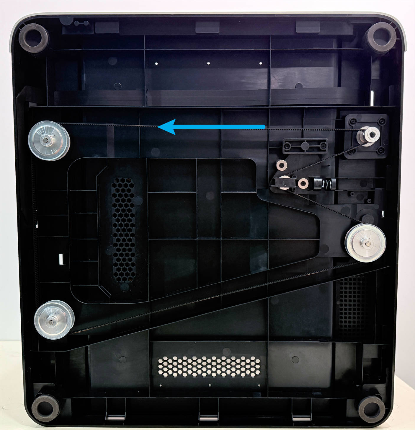
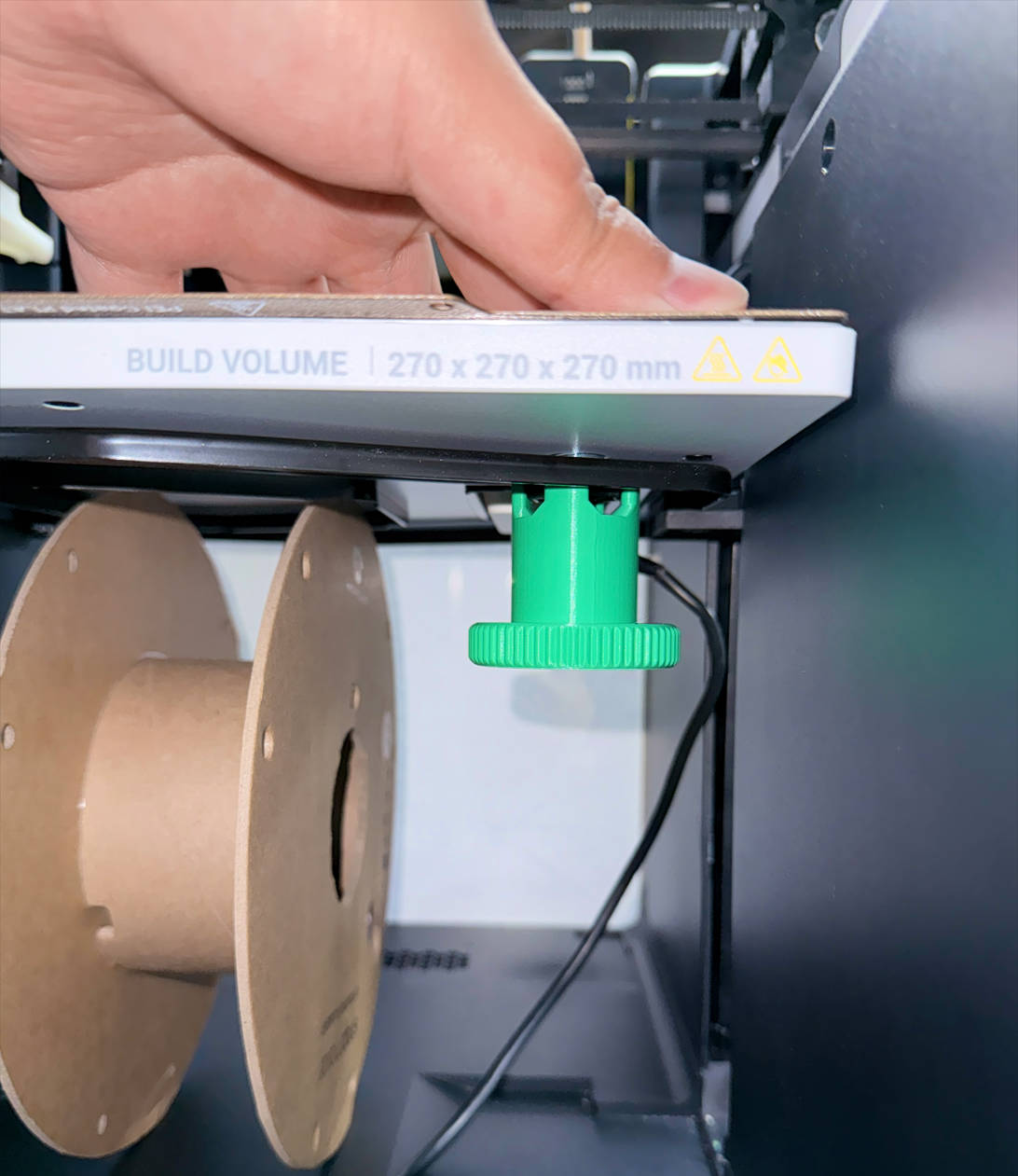
(1) At the bottom of the machine, locate the timing belt. Pull it leftward to raise the heated bed.
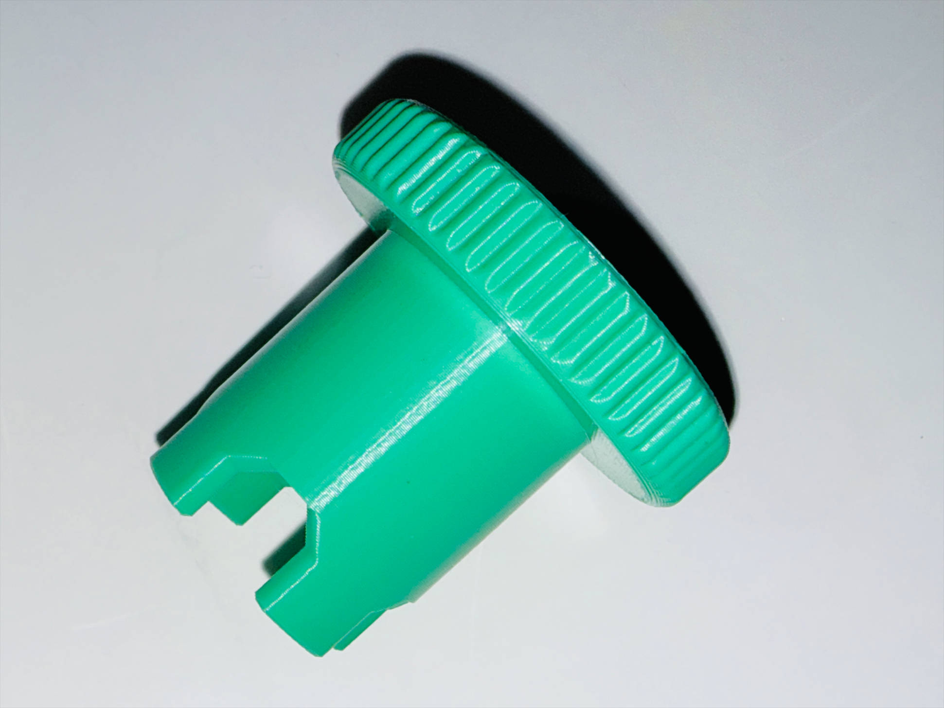
(2) Remove the four nuts at the bottom of the heated bed. You can use the printed auxiliary tool if need.
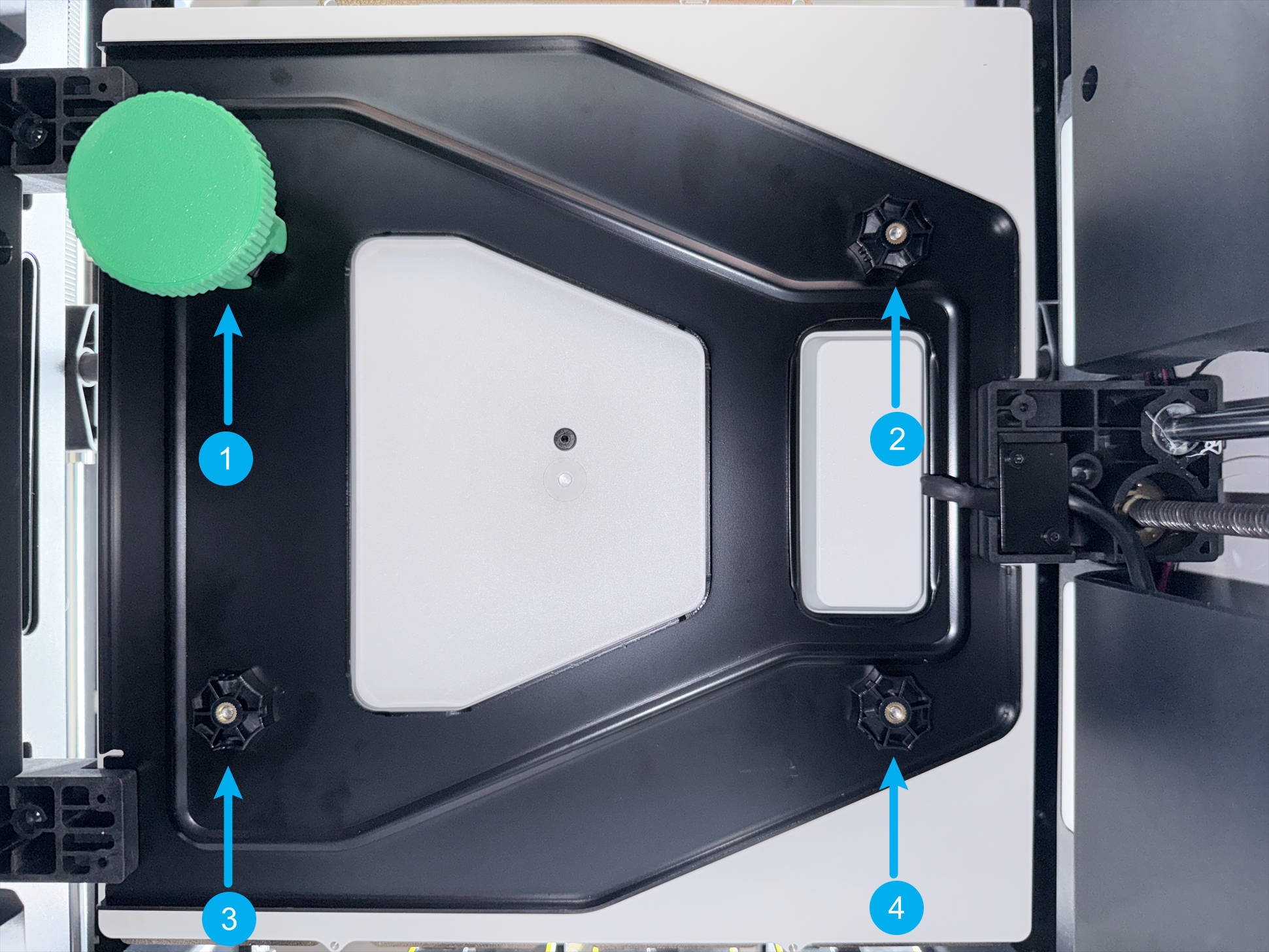
(3) If it is rather difficult to operate, please install the PEI steel sheet first. While unscrewing the nuts, press down on the corresponding corner of the heated bed and place a filament spool underneath the heated bed to prevent it from dropping.
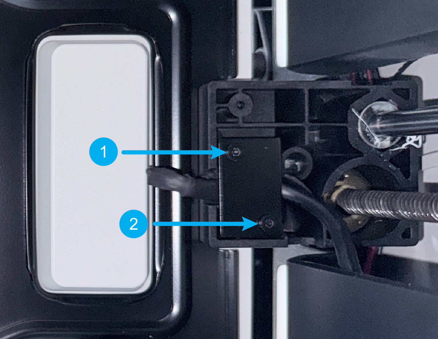
(4) Use an H2.0 hex key to remove the two screws on the heated bed cable clamp, then detach the clamp.
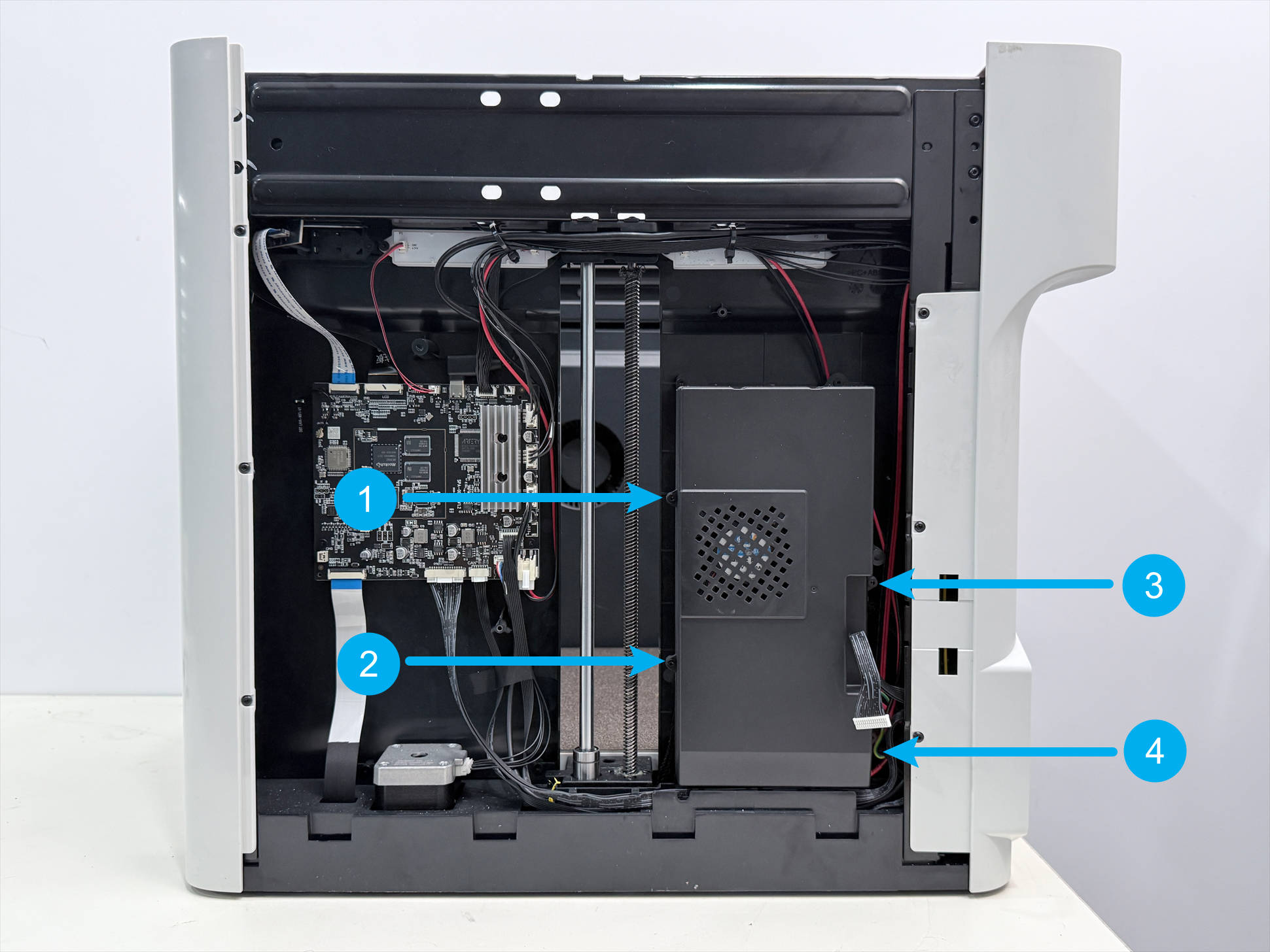
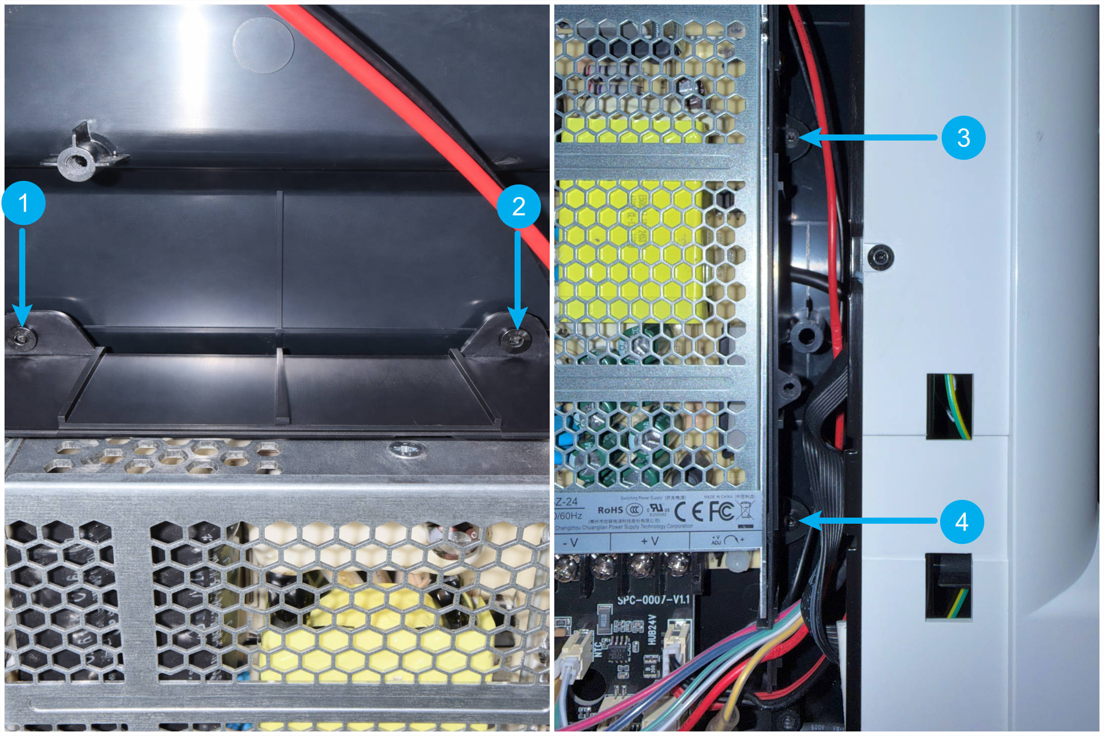
(5) Use an H2.0 hex key to remove the four screws on the power supply housing, disconnect the power supply cooling fan, and remove the power supply housing.
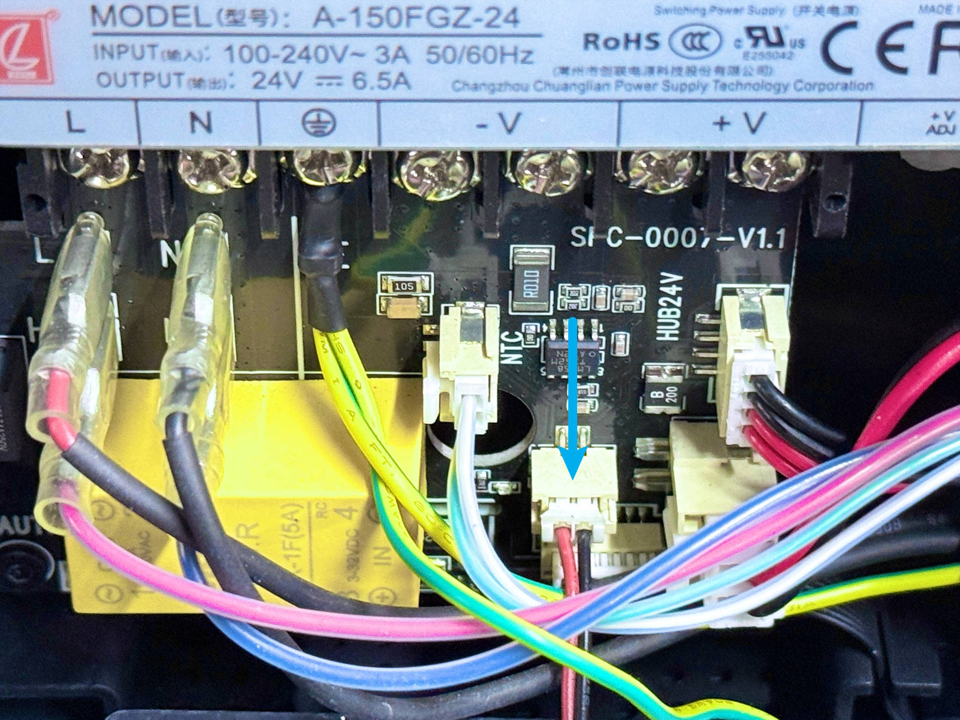
(6) Press the metal tab inside the terminal to disconnect the heated bed cable.
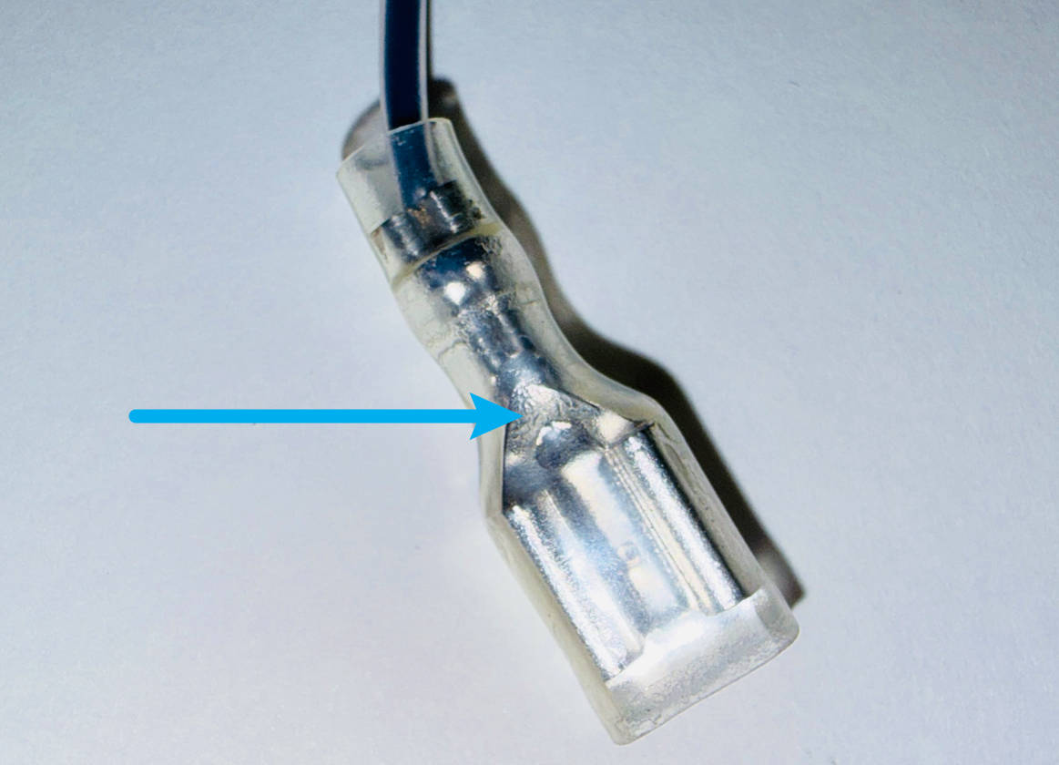
| No. | Illustration | Description | Port |
|---|---|---|---|
| 1 | 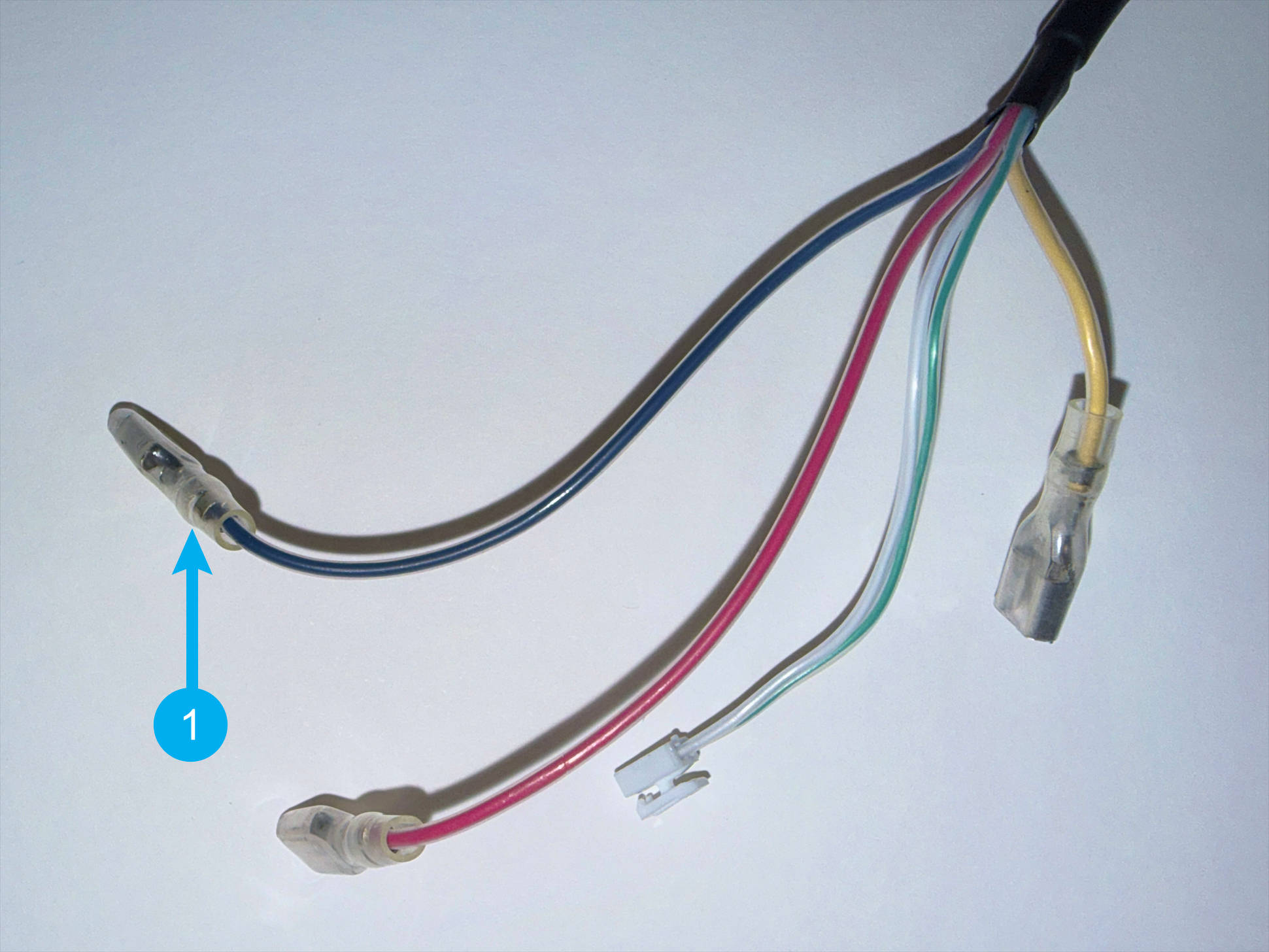 |
Heated bed-N | 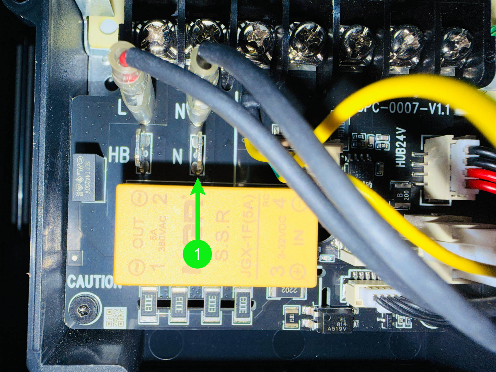 |
| 2 | 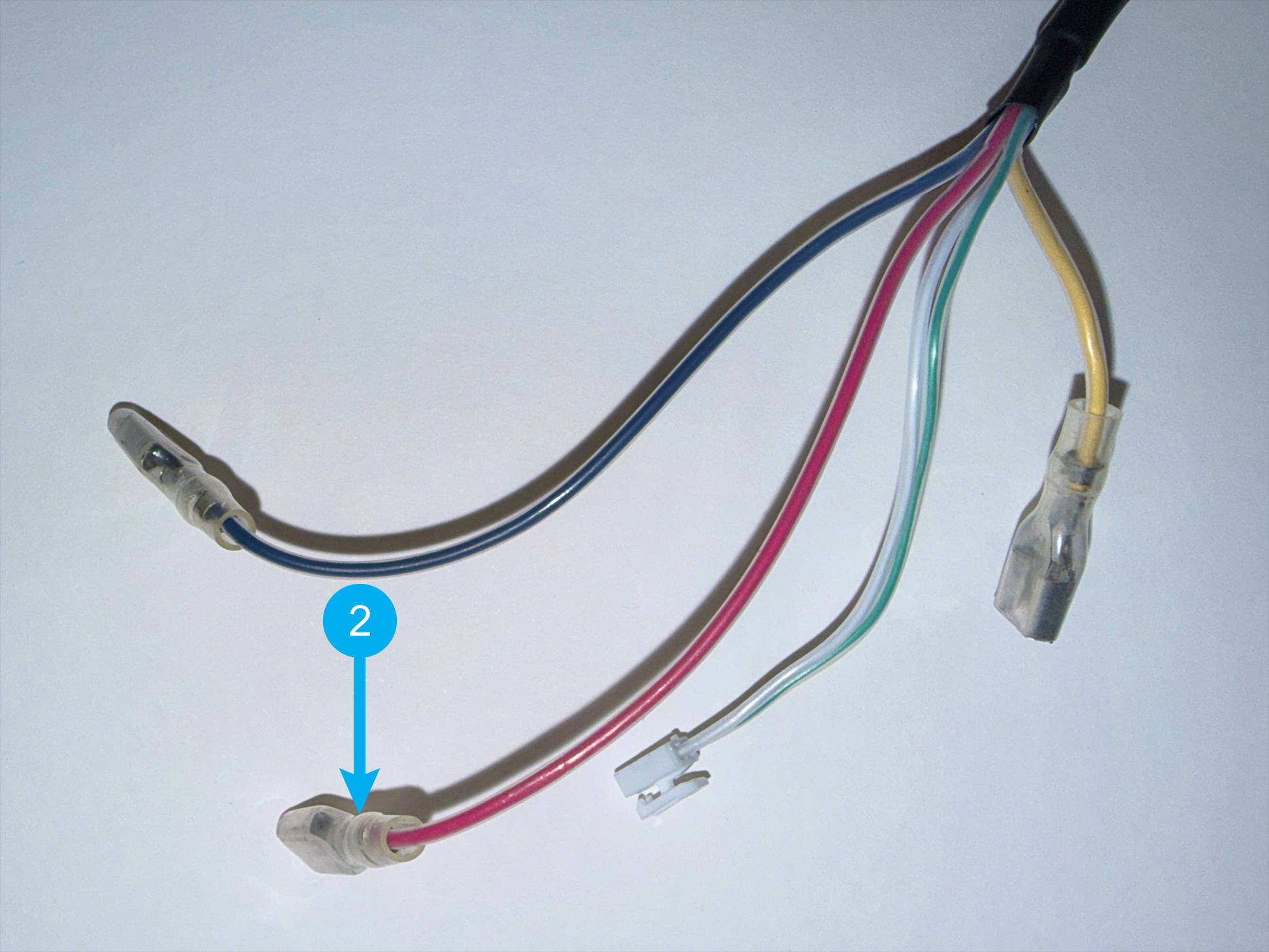 |
Heated bed-L | 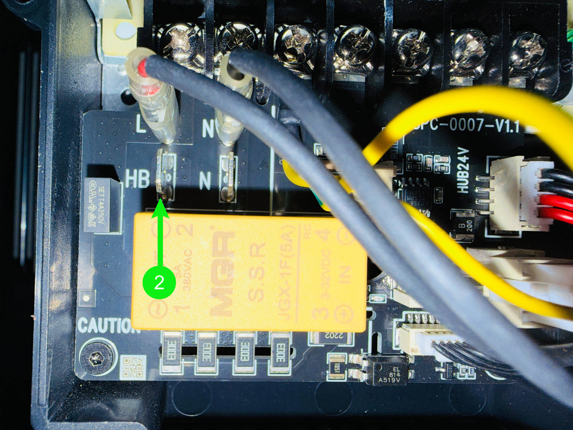 |
| 3 | 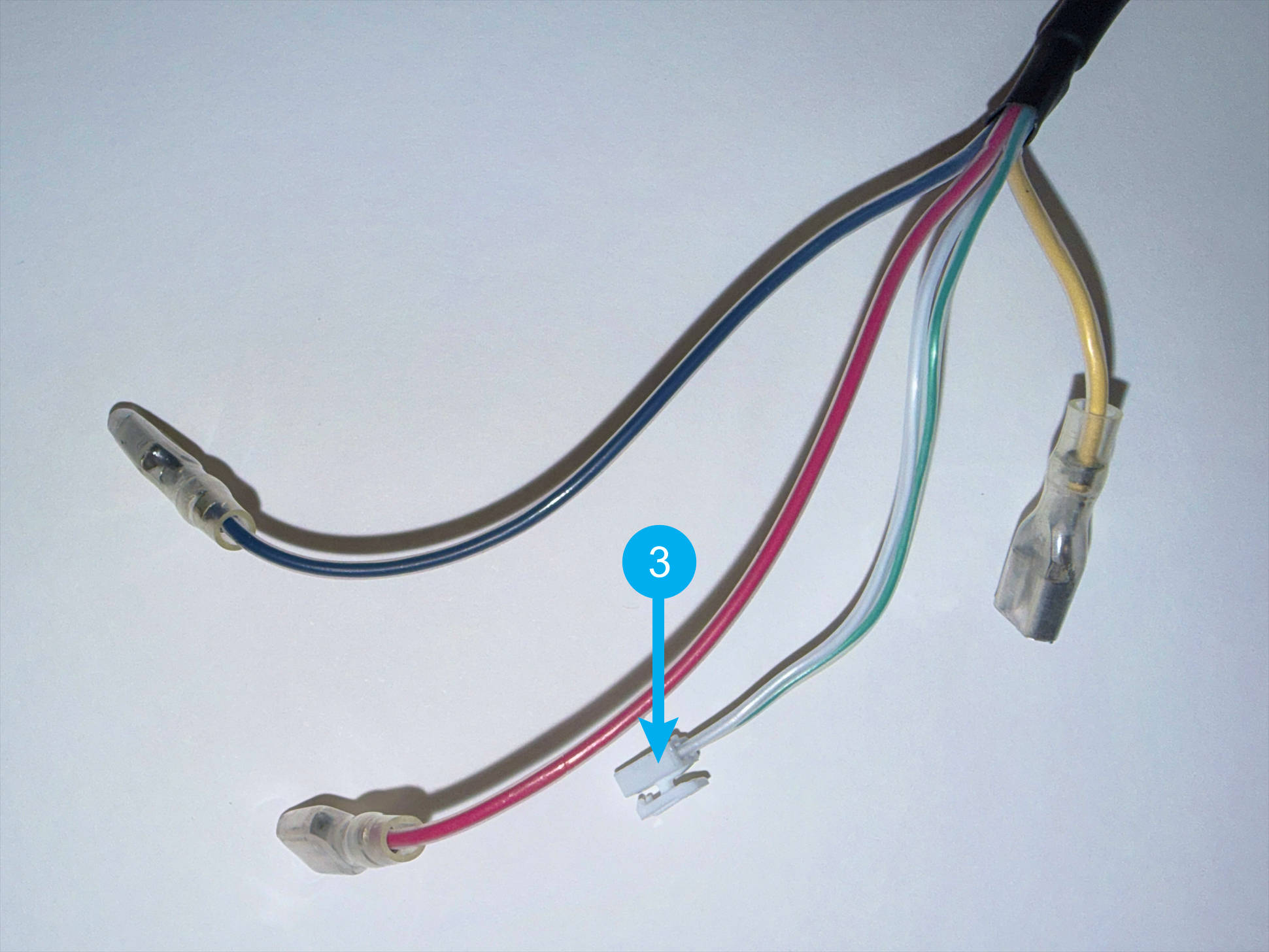 |
Heated bed-NTC | 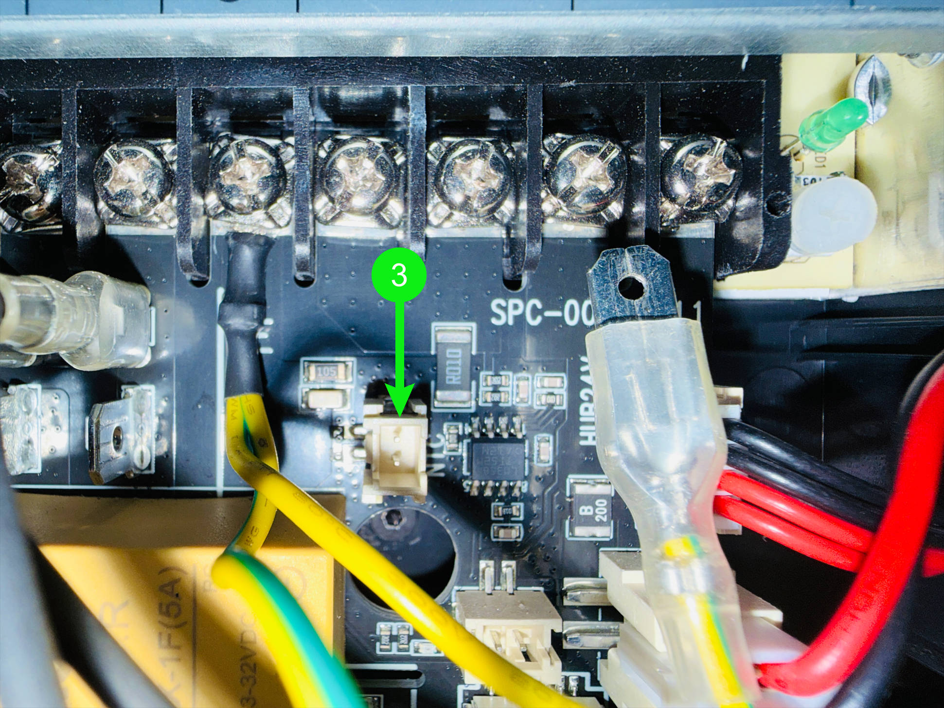 |
| 4 | 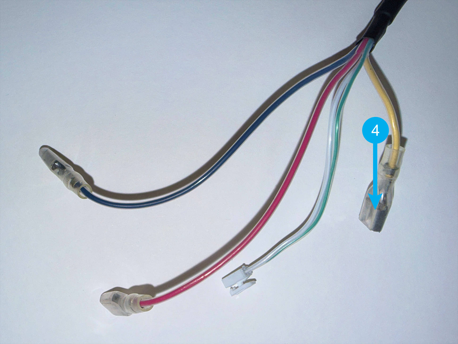 |
Heated bed-PE | 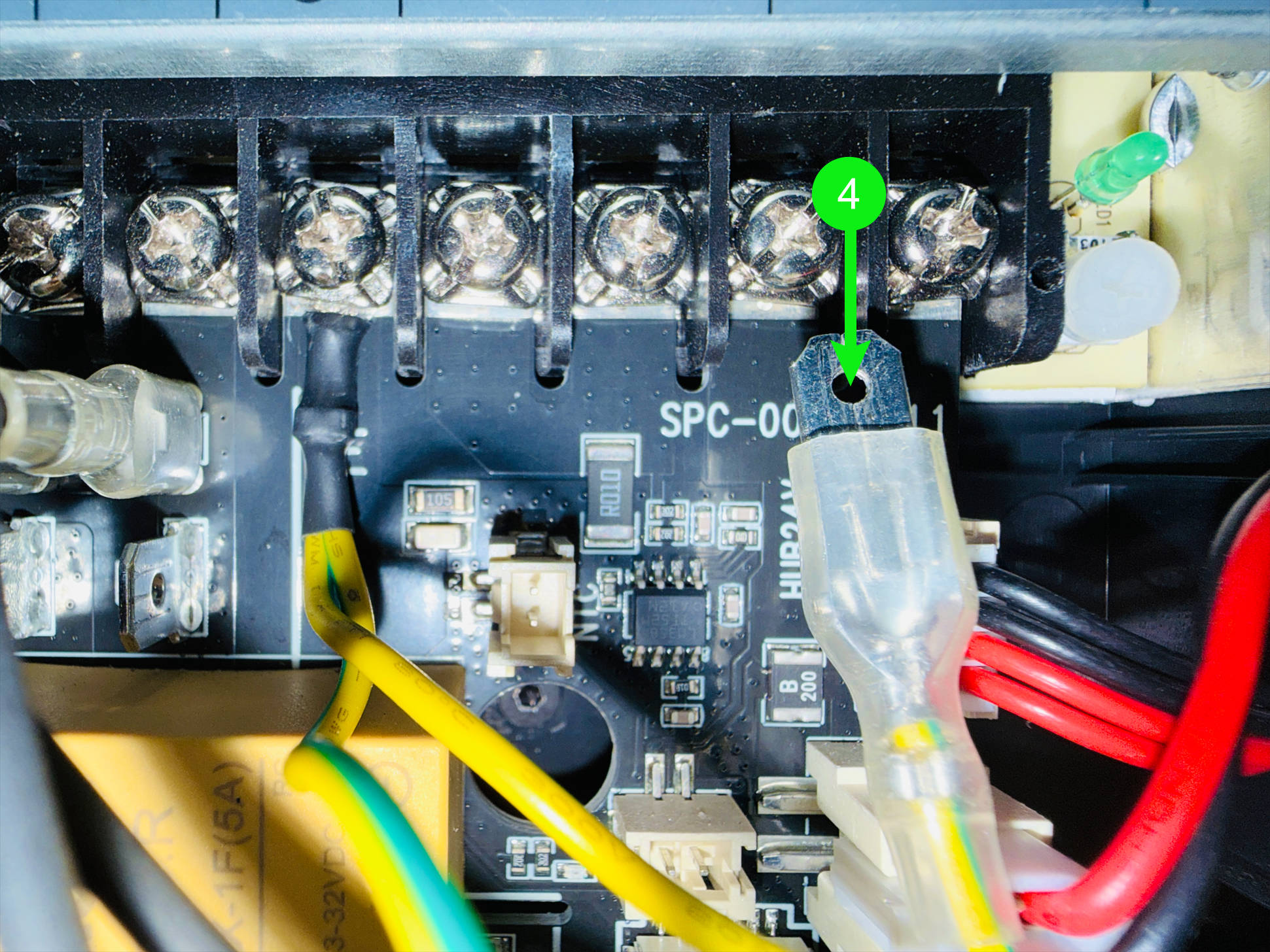 |
(7) Use an H2.0 hex key to remove the four screws shown in the image to create some clearance behind the power supply. Then route the heated bed cable through the back of the power supply and remove the heated bed.
¶ Step 3. Install the new heated bed
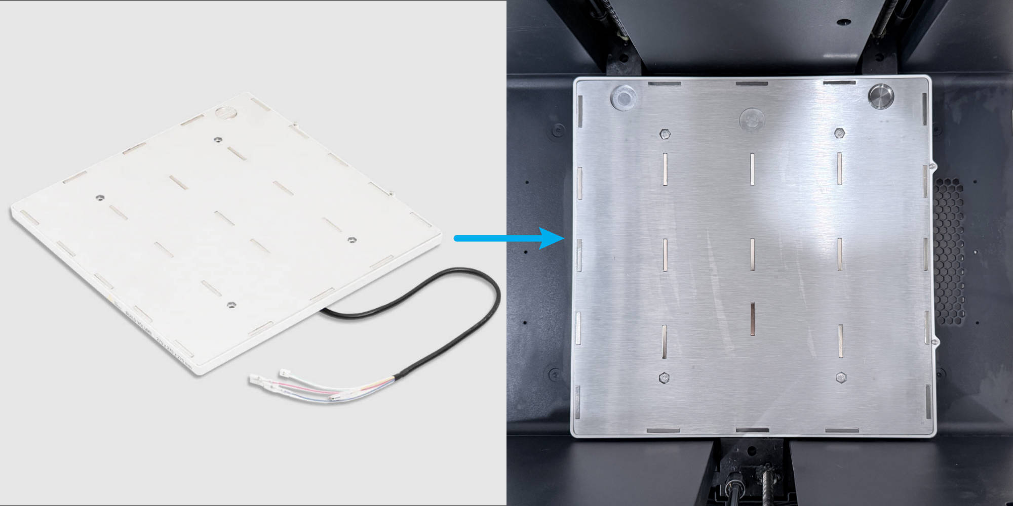
(1) Install the PEI steel sheet onto the new heated bed. Align the springs at the bottom of the heated bed with the raised holes on the sheet metal, and route the heated bed cable through the sheet metal following the path shown in the image.
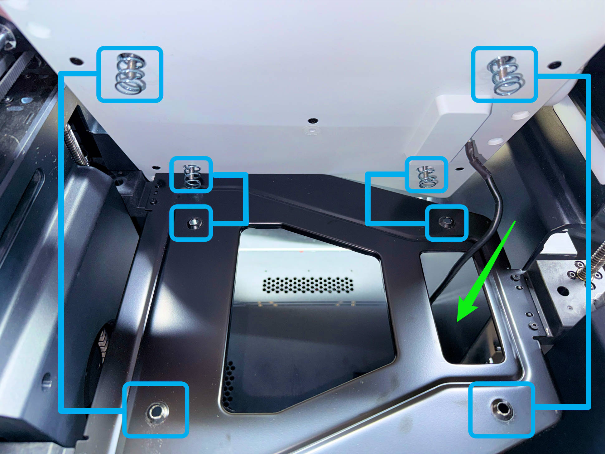
(2) Place a filament spool underneath. Press down on the corner of the heated bed so the screws at the bottom pass through the sheet metal, then tighten the nuts.
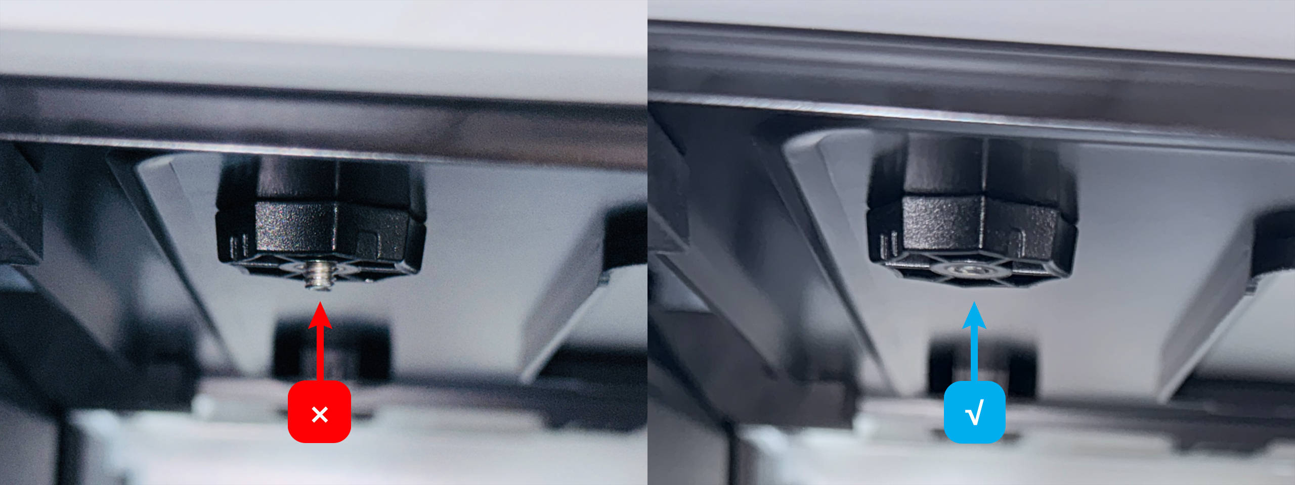
(3) Make sure the bottom surface of the screw is flush with the bottom surface of the nut. Tighten the other three nuts in the same way.
(4) Press the heated bed cable into the groove and install the cable clamp.
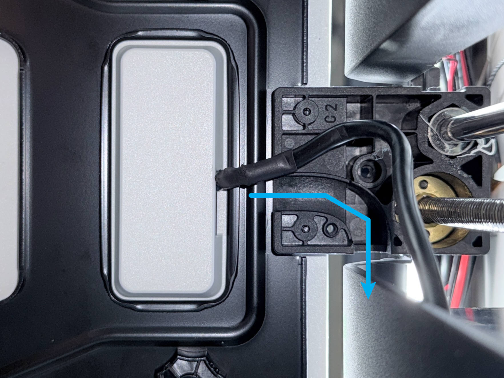
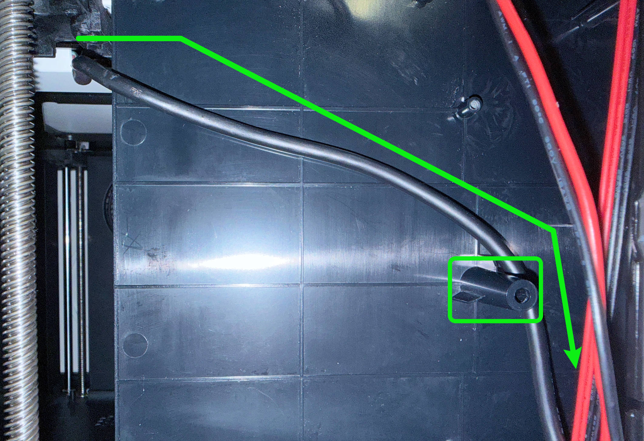
(5) Route the heated bed cable around the back of the power supply and above the screw post shown in the image, then pull it to the bottom-right corner.
If too much slack remains between the lead screw and the inner side panel, the cable may easily wear when the heated bed moves up and down. Please pay close attention to this!
(6) Connect the heated bed cable.
| No. | Illustration | Description | Port |
|---|---|---|---|
| 1 | |
Heated bed-N | |
| 2 | |
Heated bed-L | |
| 3 | |
Heated bed-NTC | |
| 4 | |
Heated bed-PE | |
¶ Step 4. Vertification
(1) Keep the panels uninstalled, reconnect the toolhead USB cable, and power on the machine.
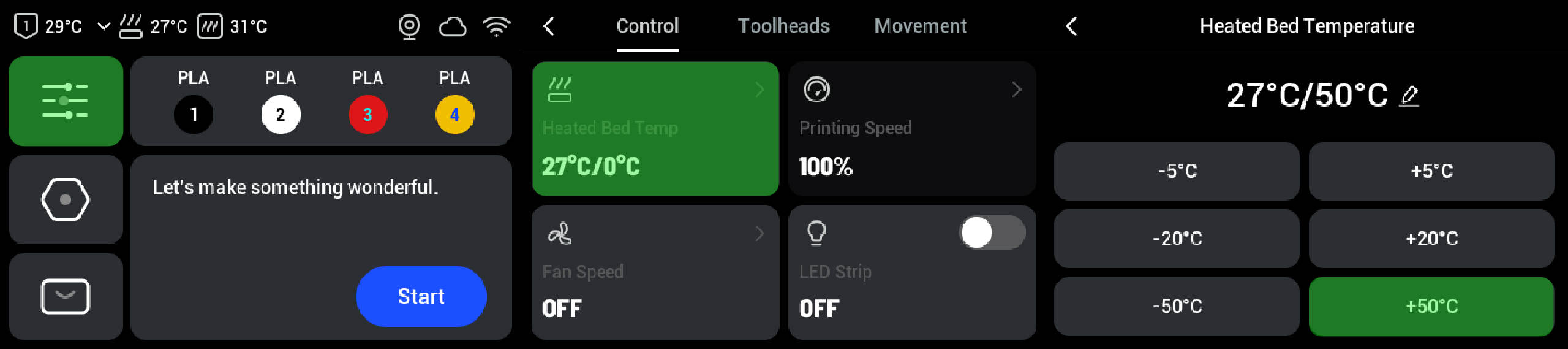
(2) Manually heat up the heated bed and check whether there are any abnormal conditions.
¶ Step 5. Restore the machine
(1) Power off and unplug the machine, then use an H2.0 hex key to tighten the power supply mounting screws.
(2) Pull the timing belt at the bottom of the machine to raise or lower the heated bed, and check whether the heated bed cable is twisted (see example below). If so, loosen the screws from the previous step and reroute the cable.
(3) Organize the wiring inside the power supply box.
| No. | Description | Wire Path |
|---|---|---|
| 1 | Heated bed control cable | 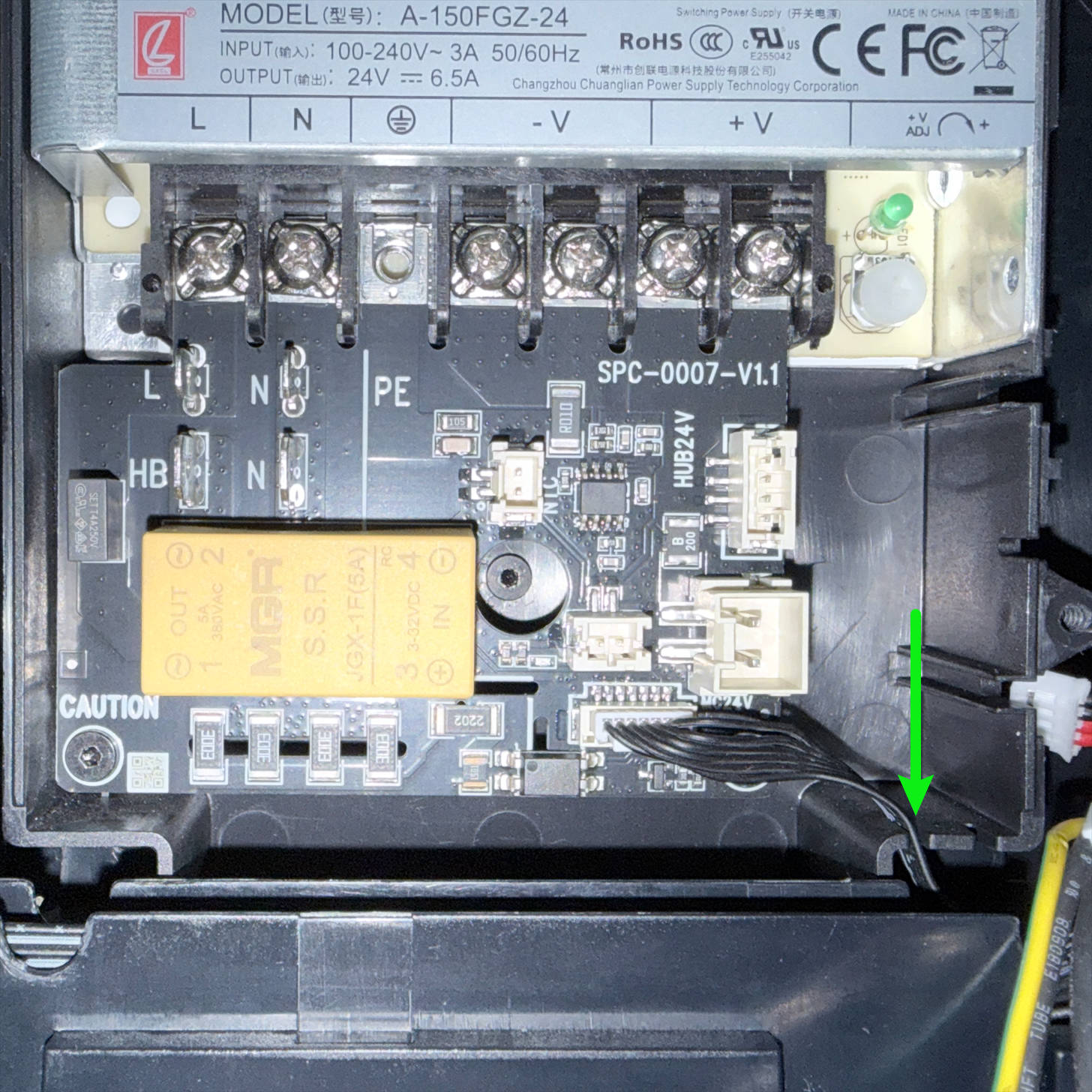 |
| 2 | Switch and heated bed PE | 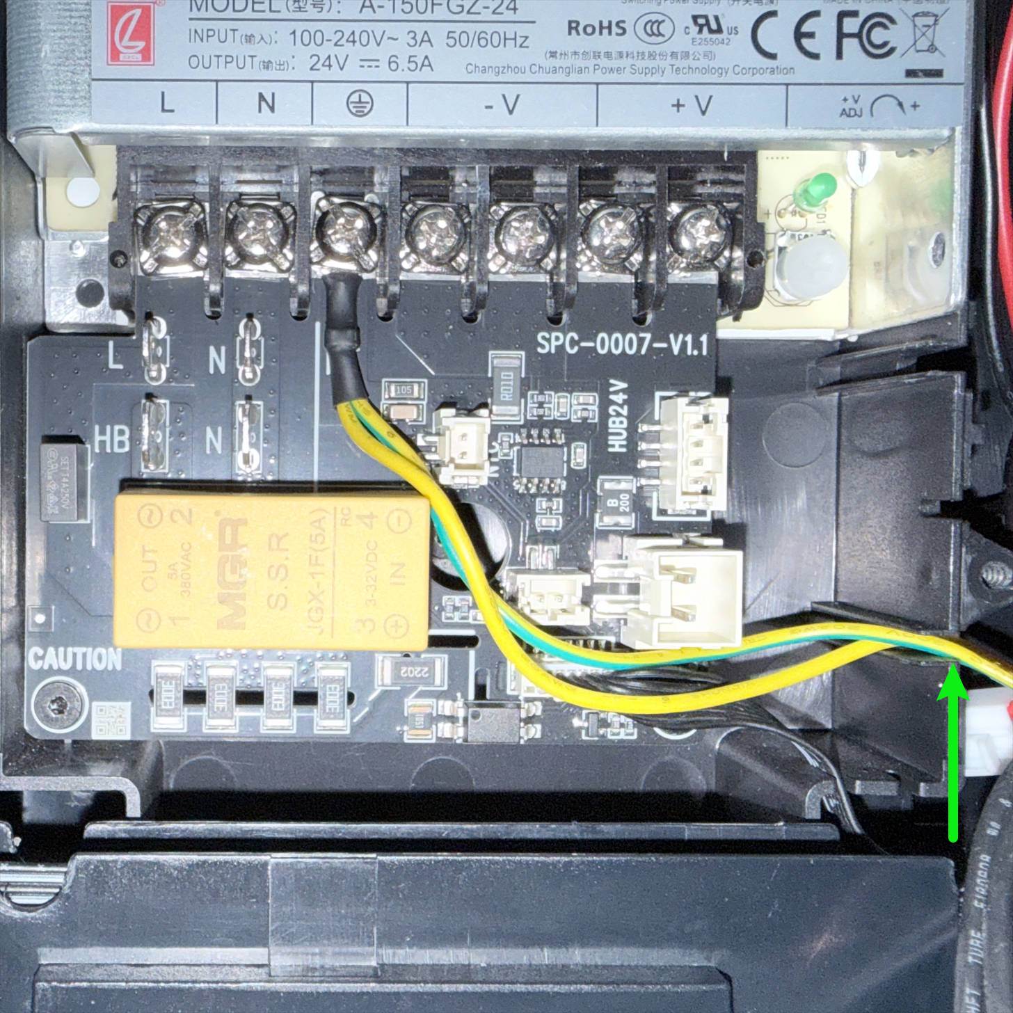 |
| 3 | Switch N & L | 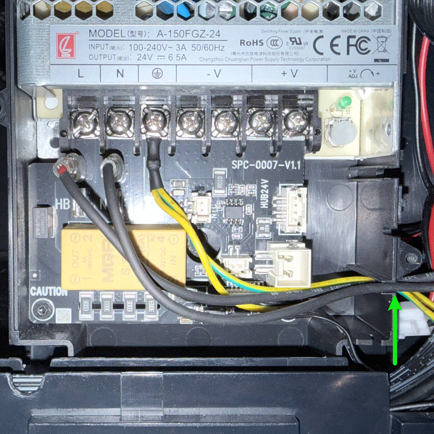 |
| 4 | Heated bed N & L & NTC | 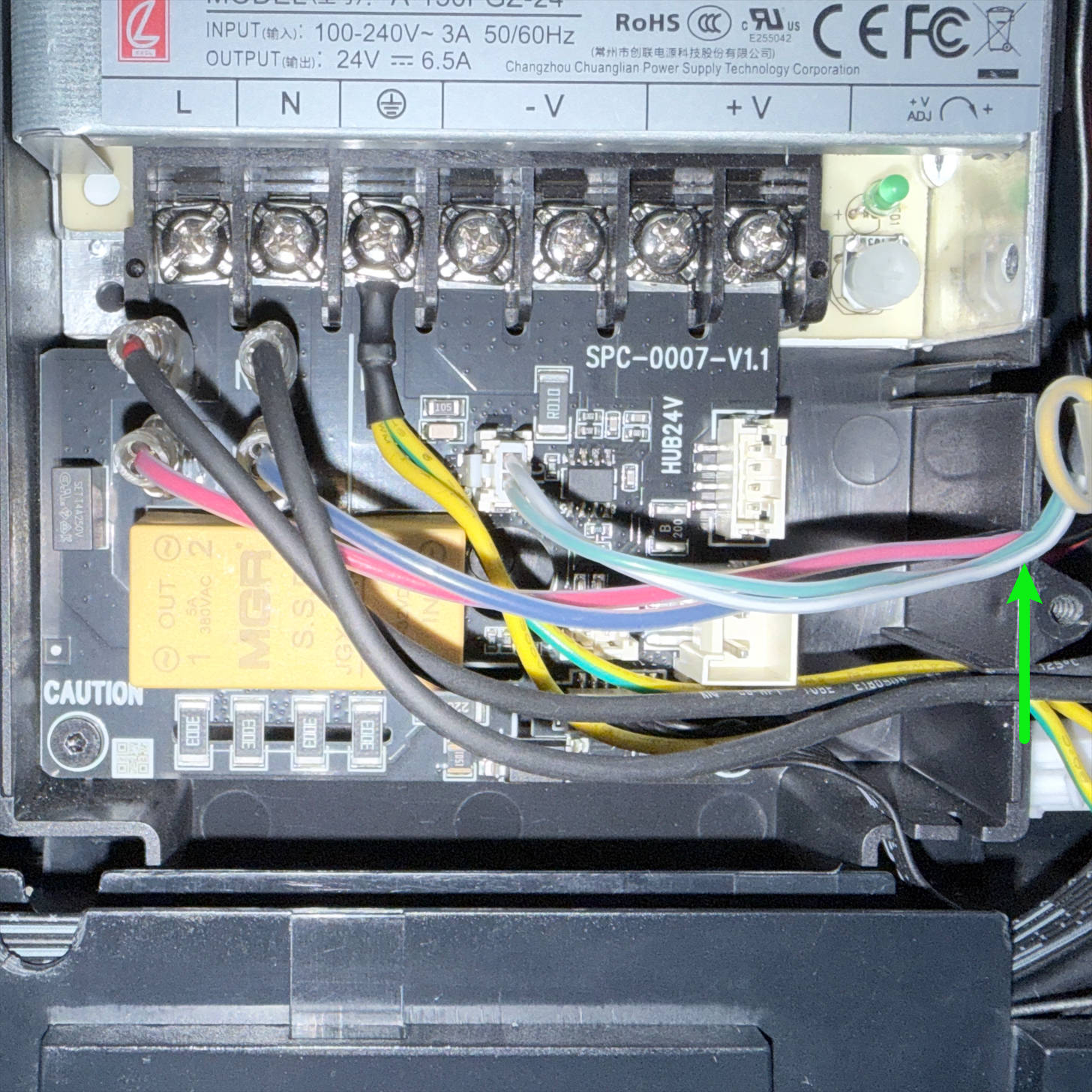 |
| 5 | Heated bed PE junction | 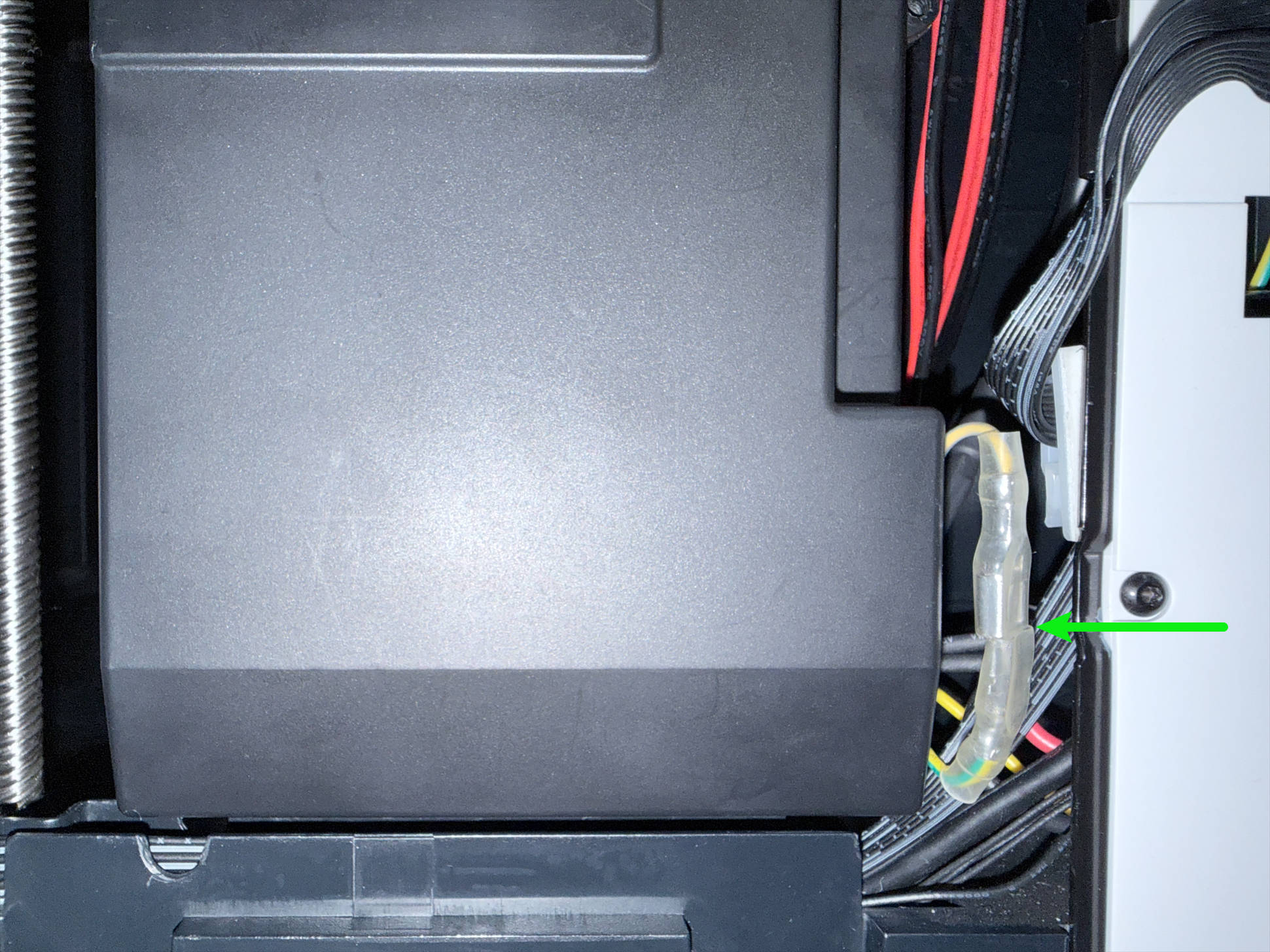 |
| 6 | Main control board and HUB board power supply | 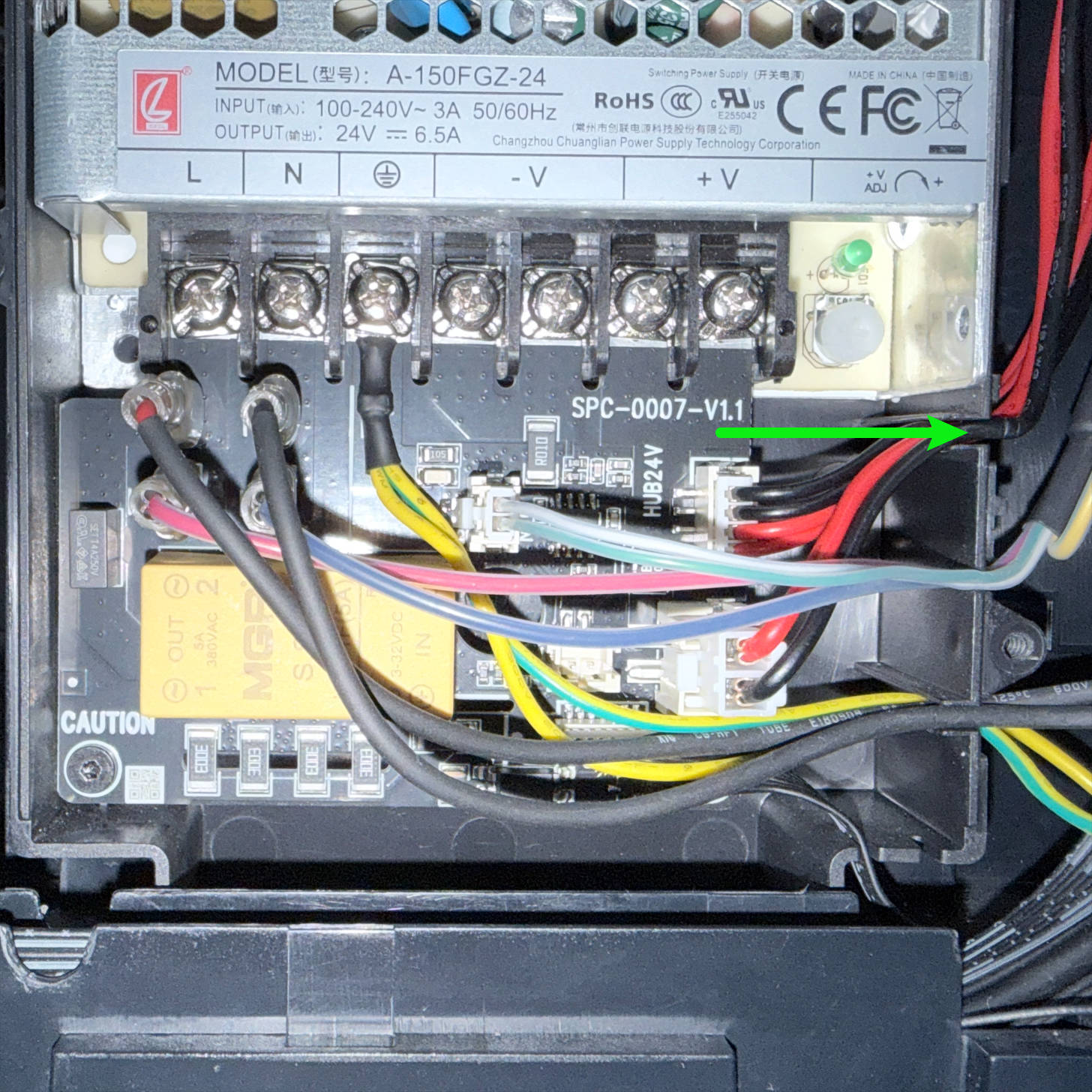 |
(4) Connect the power supply fan, install the power supply enclosure, and tighten the screws.
(5) Refer to the second half (4:28–8:39) of the side panel disassembly tutorial to restore the machine.
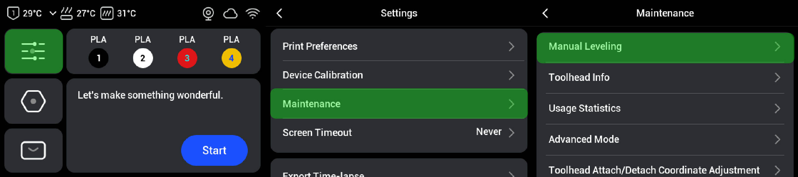
¶ Step 6. Manual leveling
After replacing the heated bed, you must perform manual bed leveling to prevent excessive bed tilt that could cause the nozzle to scrape against the heated bed.
¶ Reach out to Snapmaker Support
After following the troubleshooting steps, if you find it difficult to resolve your issue, kindly submit a support ticket through https://snapmaker.formcrafts.com/u1-troubleshooting-request and share your troubleshooting results with some pictures/videos. Our dedicated support team will be more than willing to assist you in resolving the issue.