¶ Overview
¶ Location
The filament runout sensor assembly is inside the extruder unit. Disassemble the toolhead and remove the extruder unit before replacing it.
¶ Complexity
Difficulty:★★☆☆☆ (easy)
Estimated time:25mins
¶ Where to Purchase
¶ Tools & Parts Required
(1) H1.5 hex key
(2) H2.0 hex key
(3) New filament runout sensor
¶ Part 1 - Remove Toolhead
¶ Step 1 - Unload filament
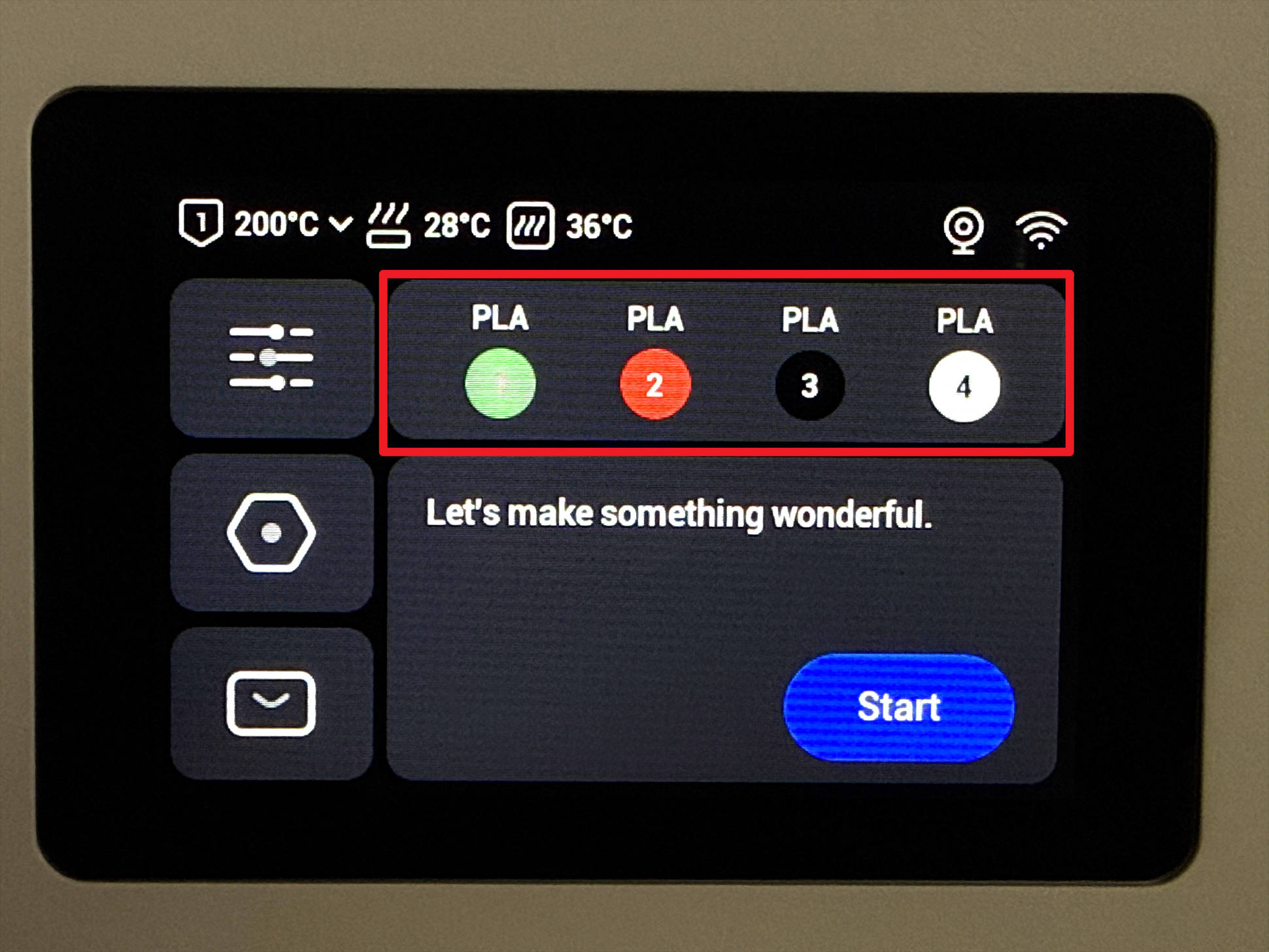
(1) Tap the filament info section on the home page.
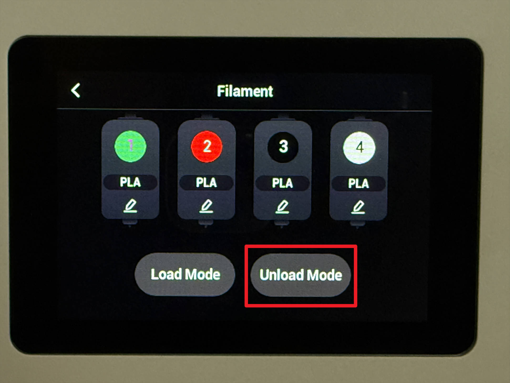
(2) Tap "Unload mode".
(3) Choose the target toolhead (e.g., Toolhead 1) and tap "Unload".
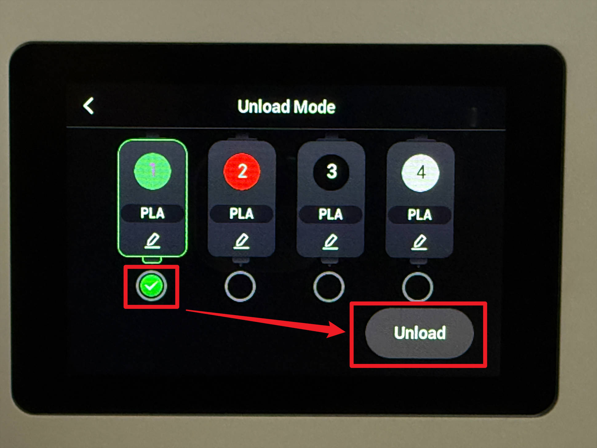
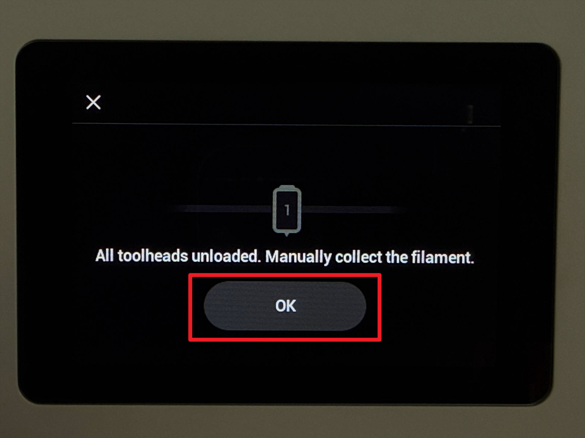
(4) Wait for the printer to finish unloading, then tap "OK".
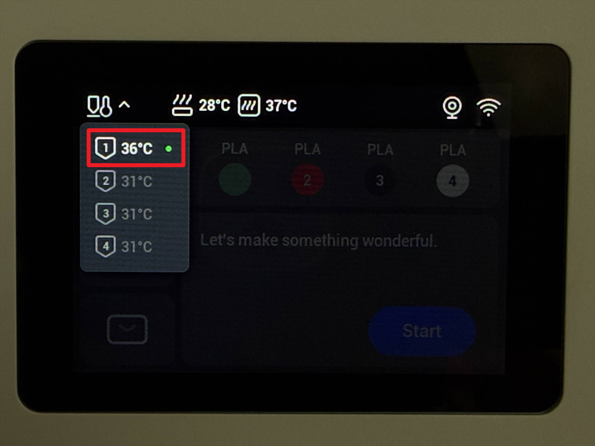
(5) Return to the home page, tap the upper-left corner to check the nozzle temperature, and wait until it cools below 40 °C.
¶ Step 2 - Detach toolhead
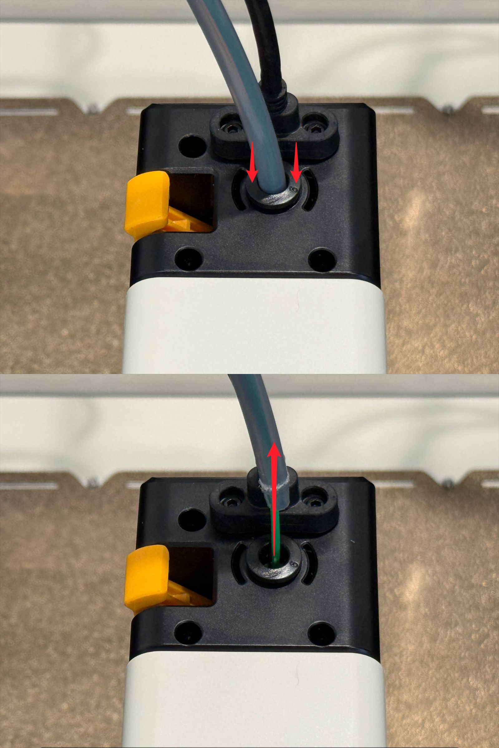
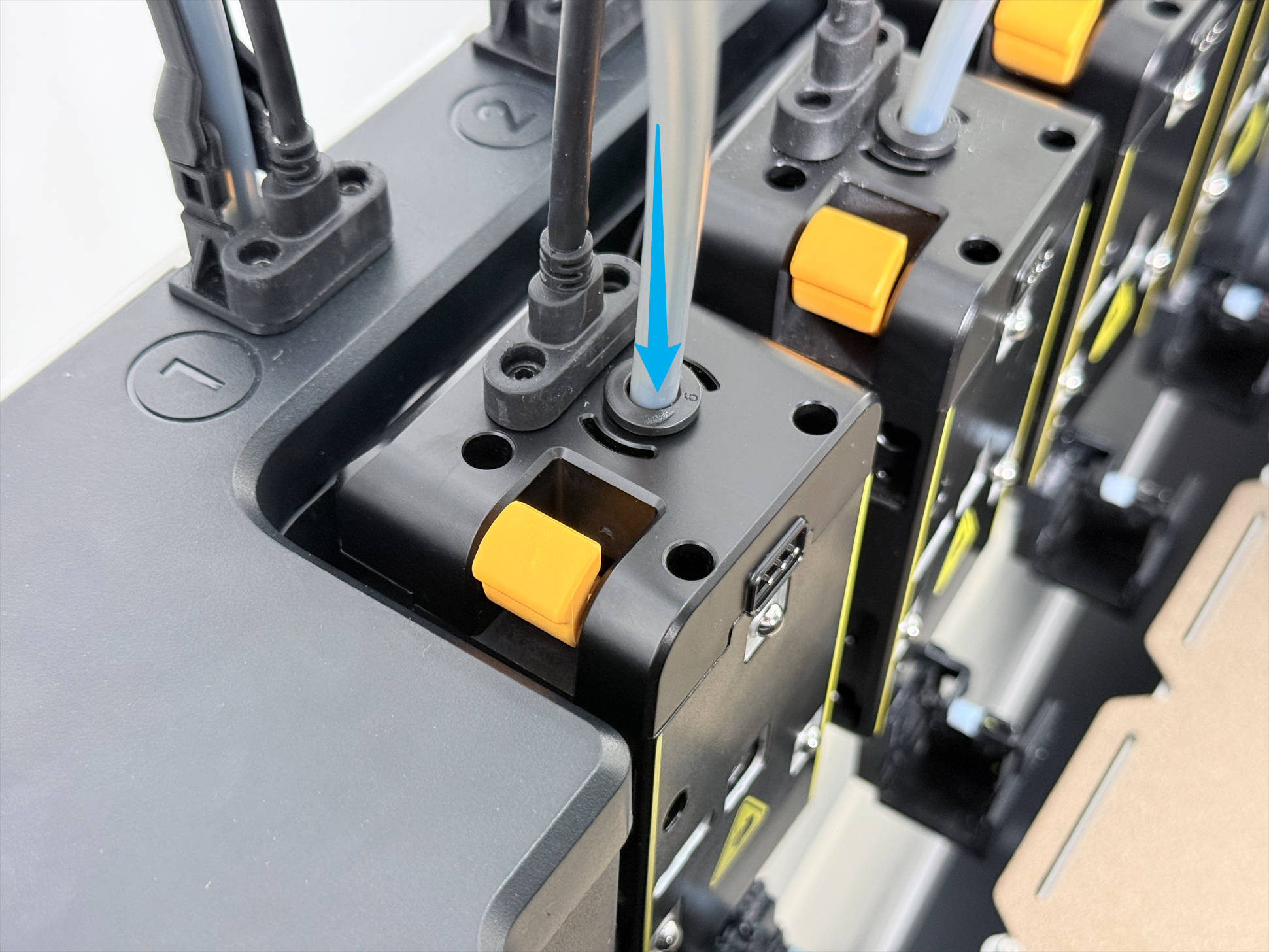
(1) Press the quick connector to pull out the filament tube.
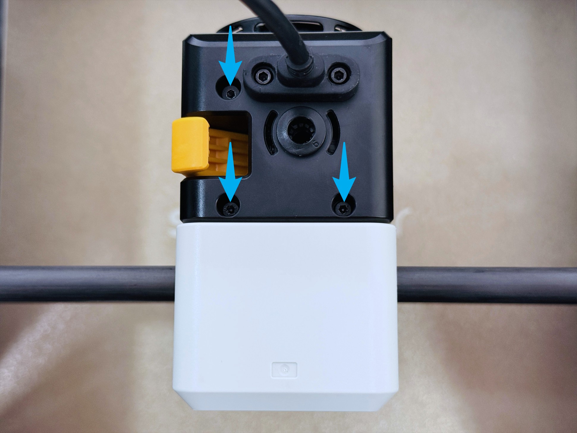
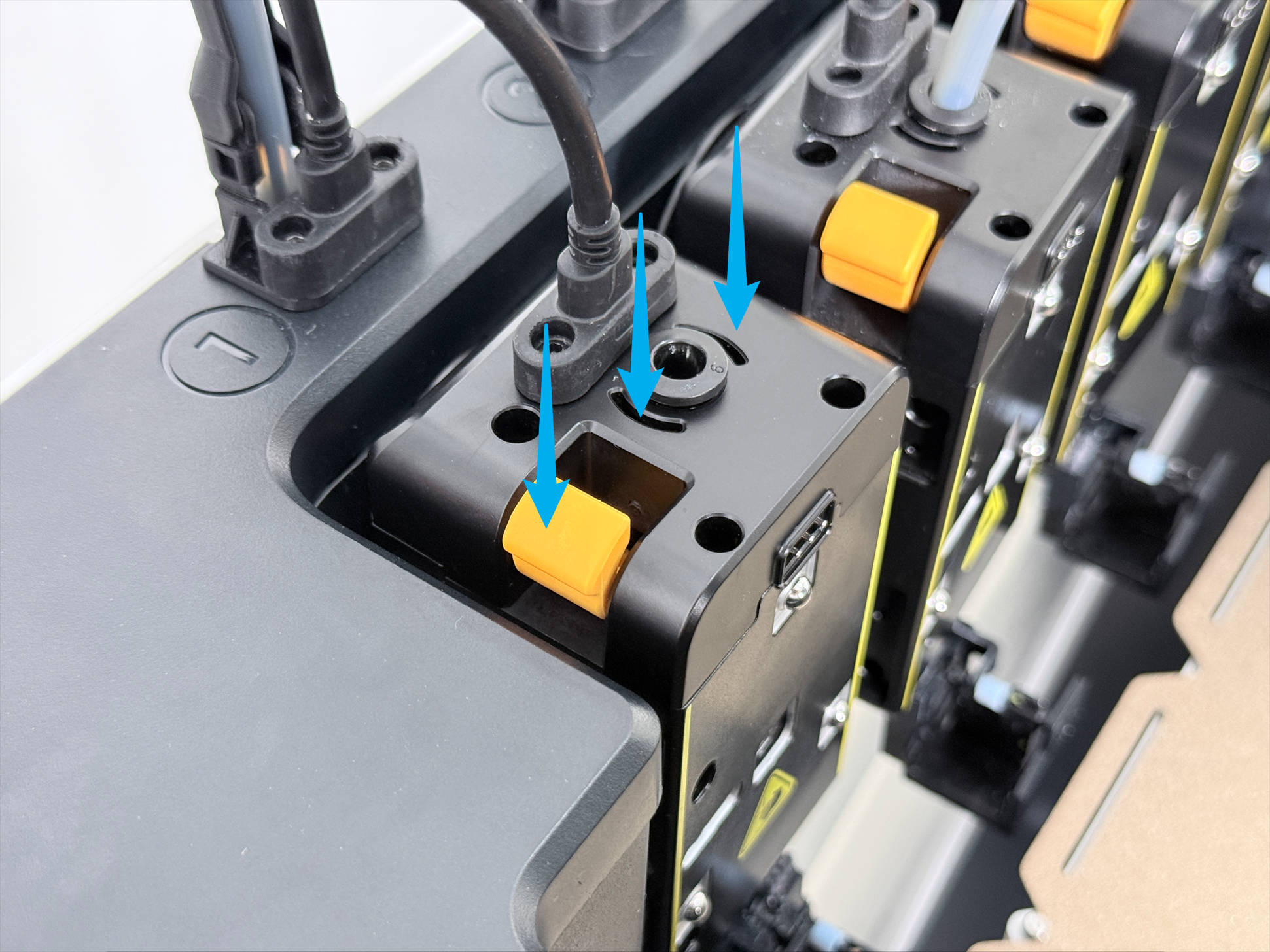
(2) Use an H2.0 hex key to remove the 3 screws.
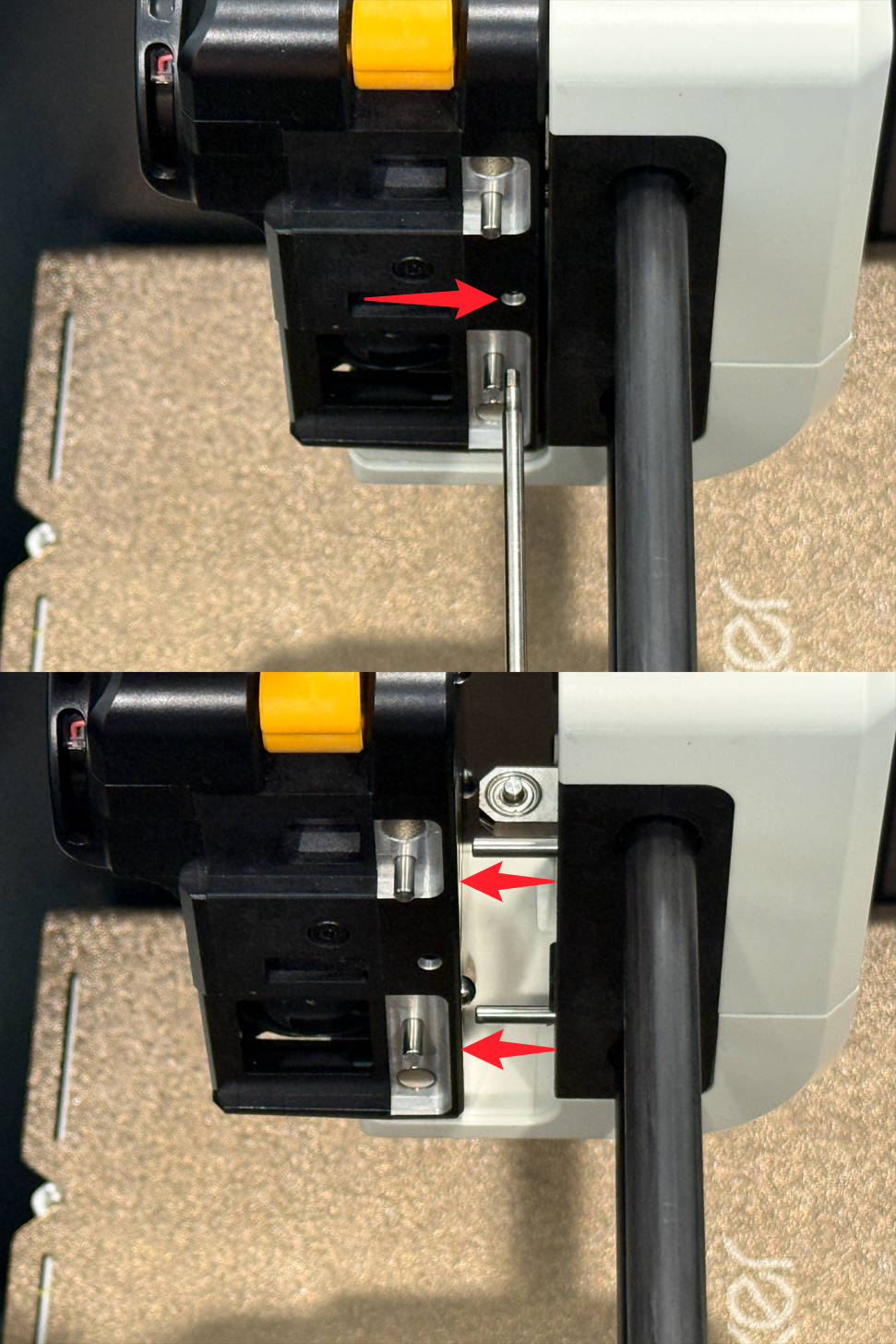
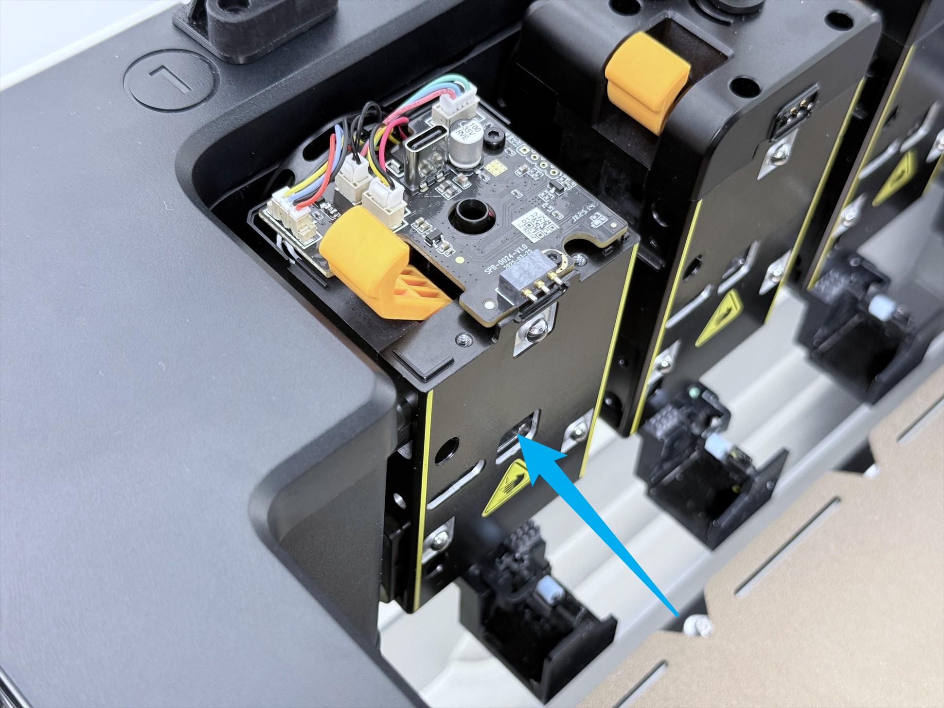
(3) Insert an H2.0 hex key into the center hole between the two locating pins, and push until you hear a "click" to detach the toolhead from the swapper.
(4) Disconnect the toolhead cable and remove the toolhead top cover.
¶ Part 2 - Replace Filament Runout Sensor
¶ Step 1 - Remove extruder unit
(1) Remove the toolhead rear cover.
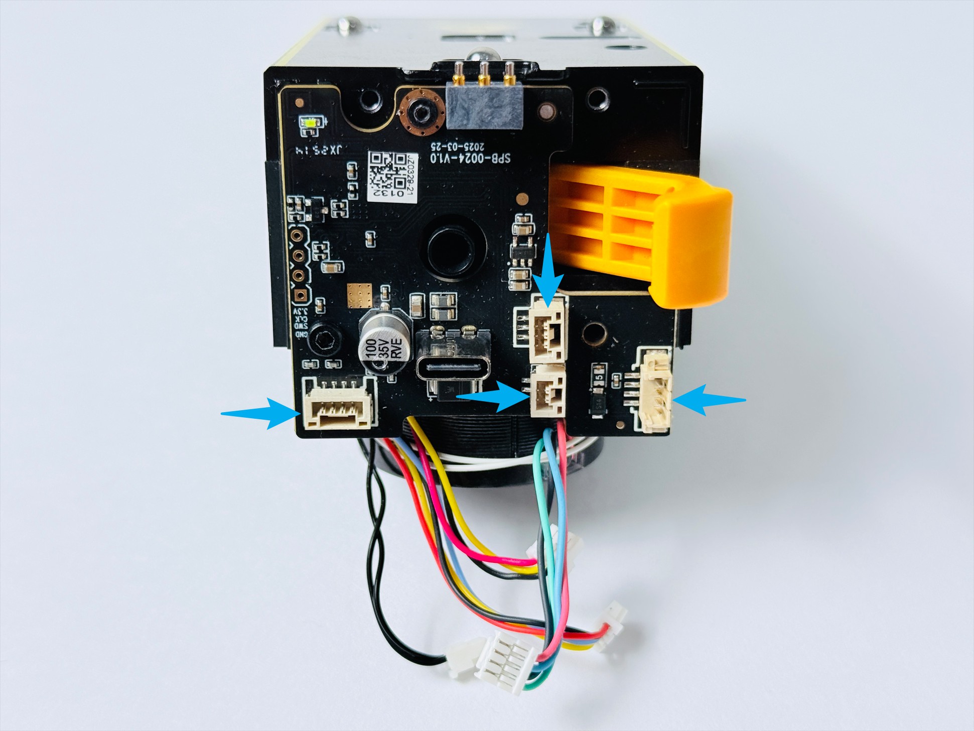
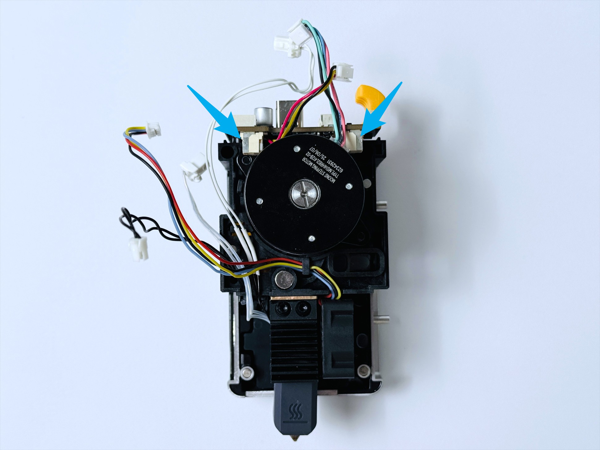
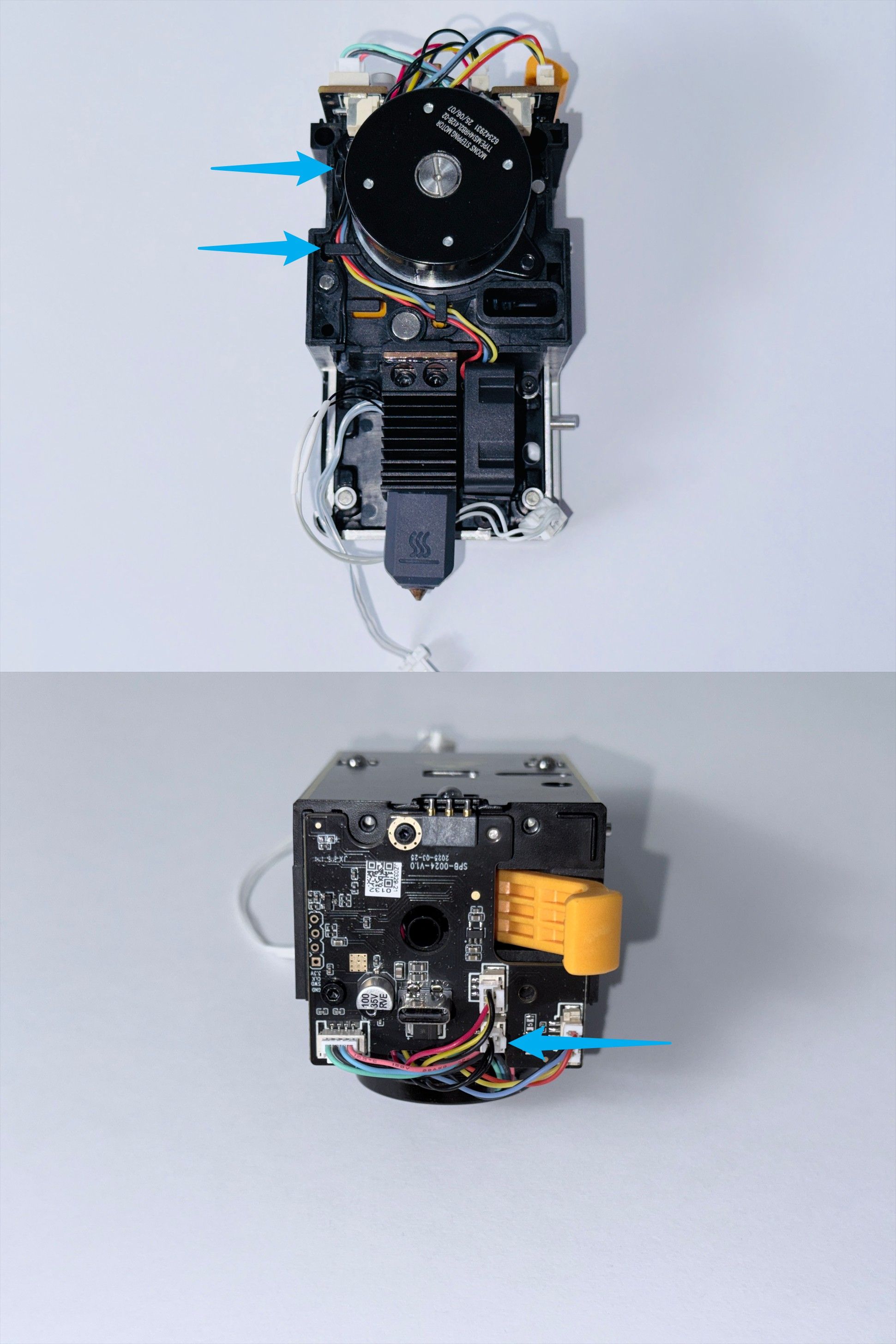
(2) Disconnect the 4 cables on top of the toolhead PCB.
(3) Press the locking clip with an H2.0 hex key to disconnect the 2 cables at the bottom of the toolhead PCB.
(4) Use H1.5 and H2.0 hex keys to remove the upper and lower screws.
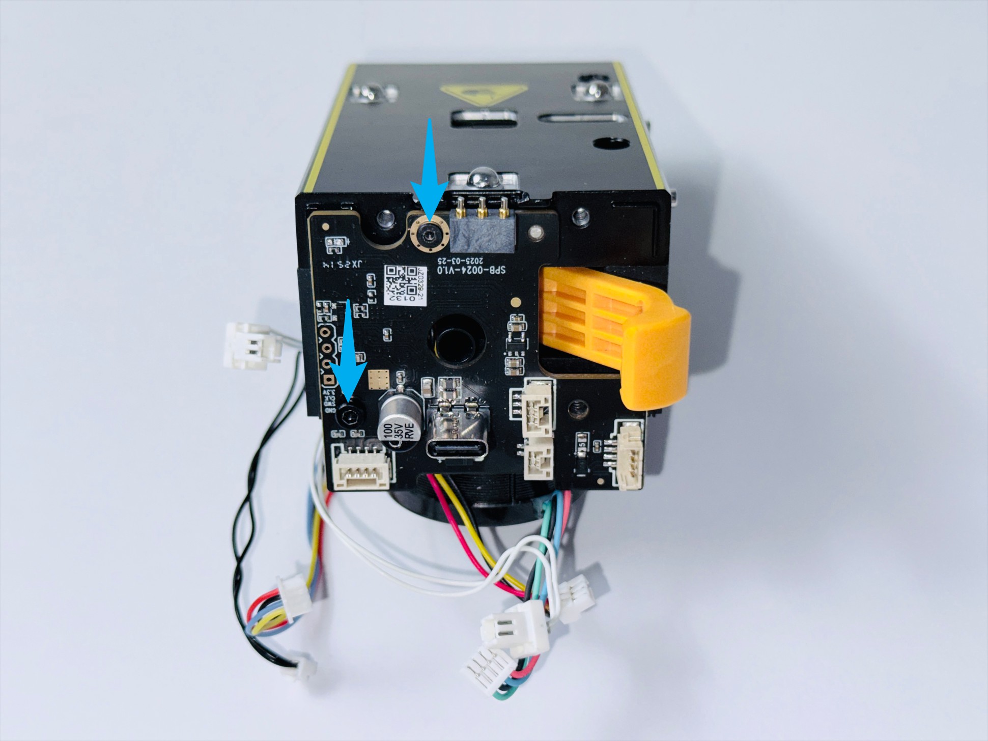
(5) Remove the toolhead PCB.
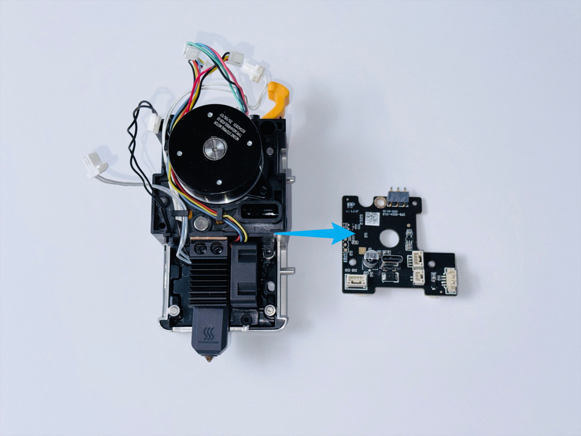
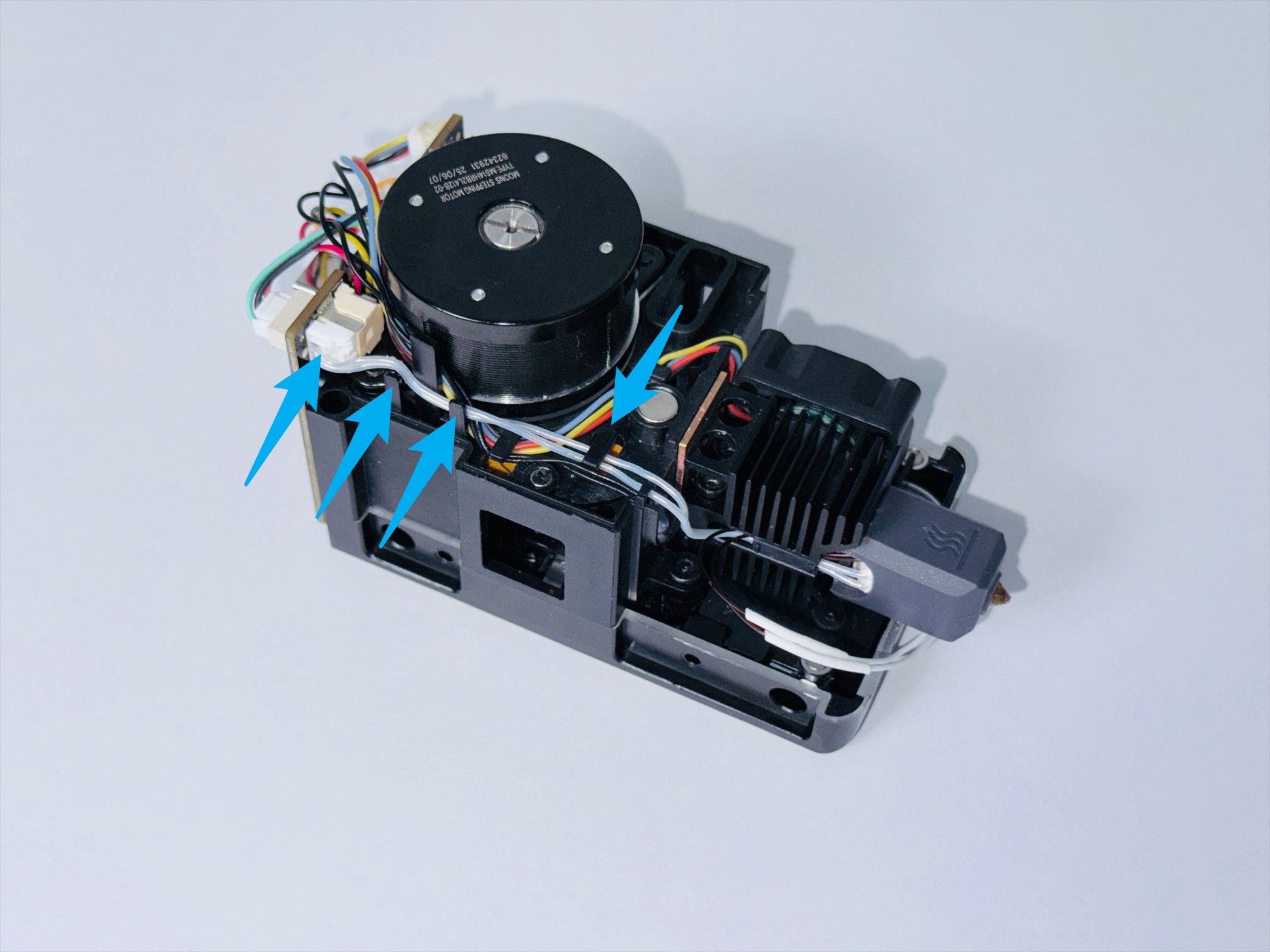
(6) Pull all cables out from the clips of the extrusion unit.
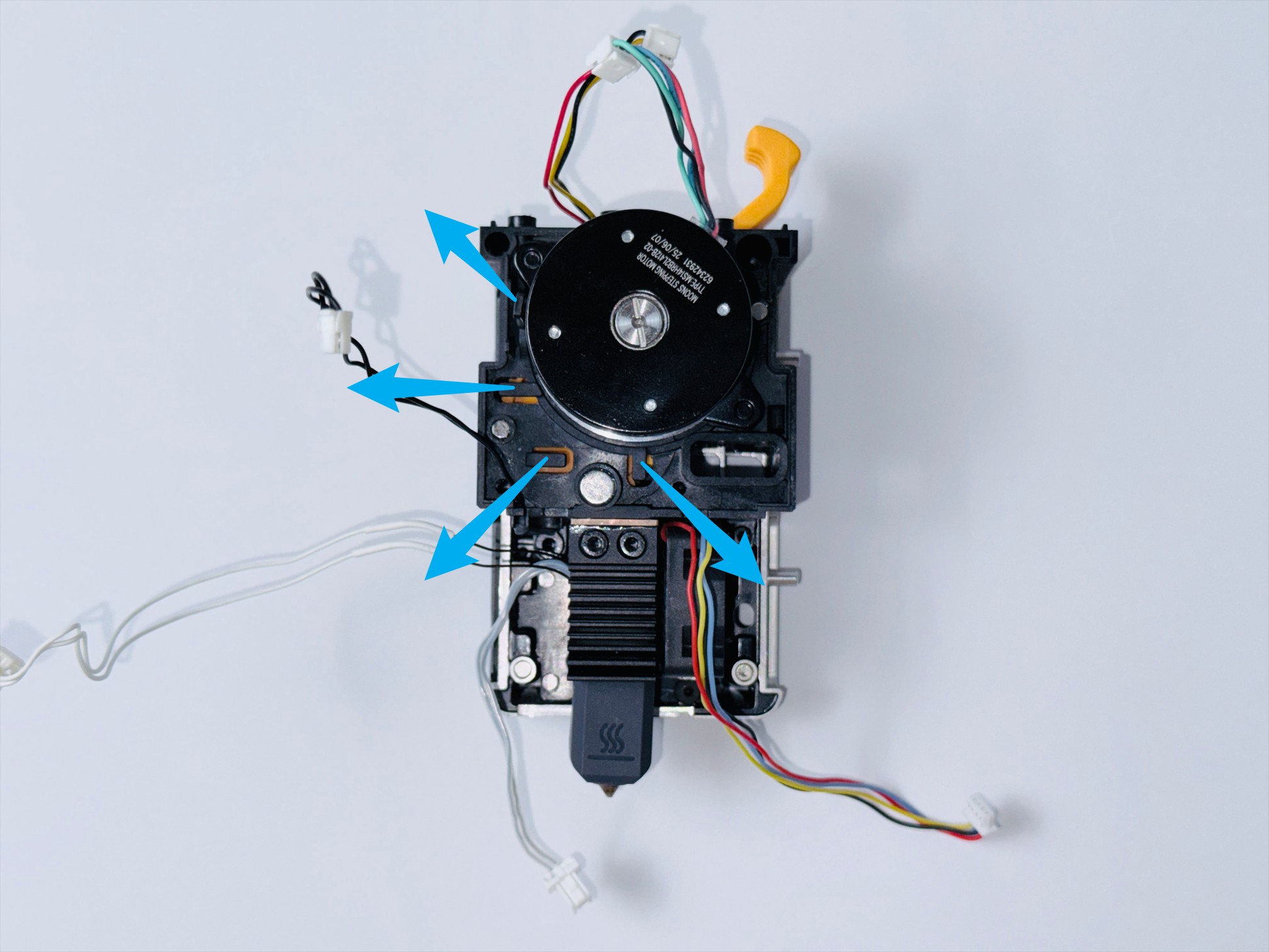
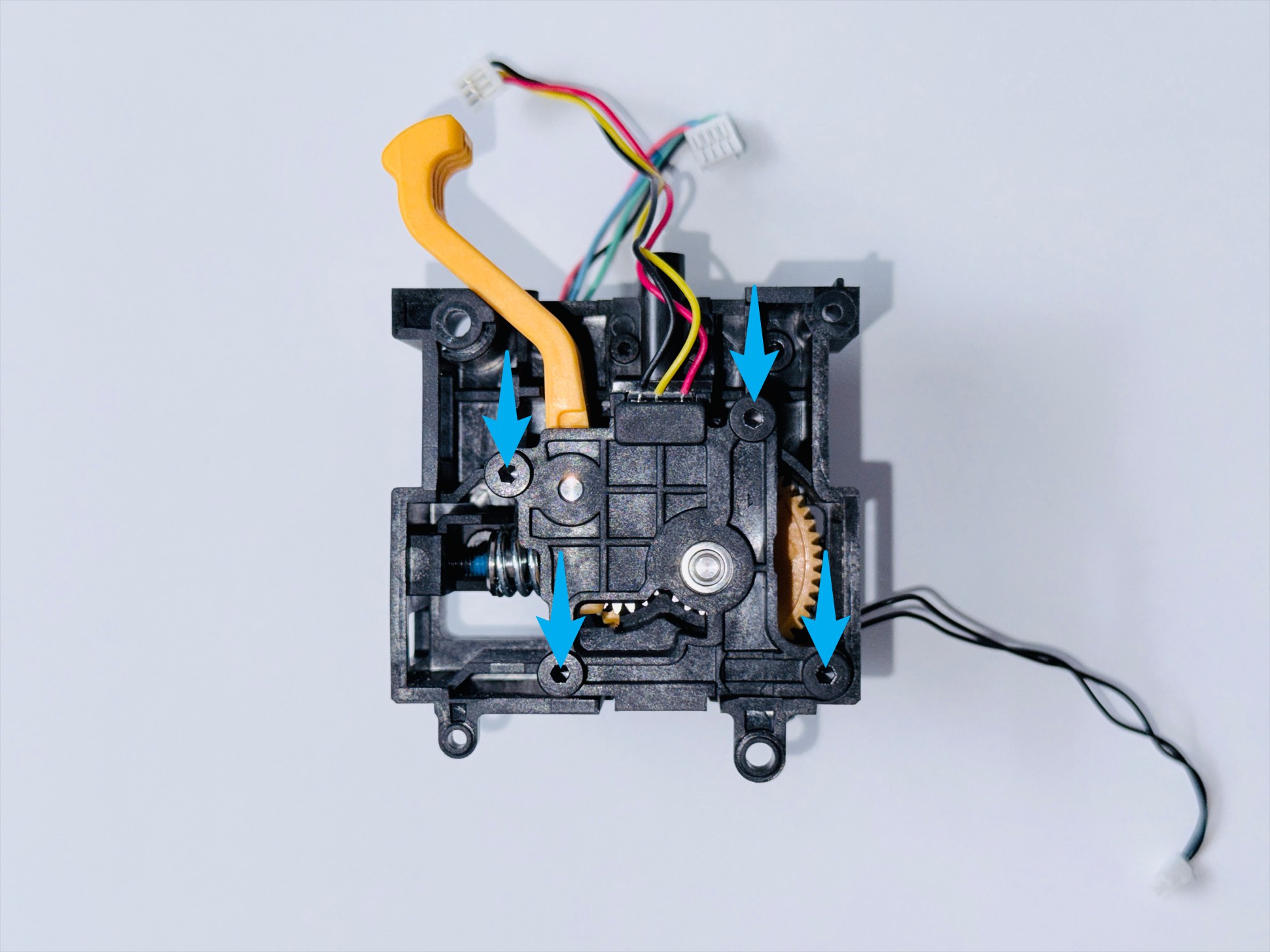
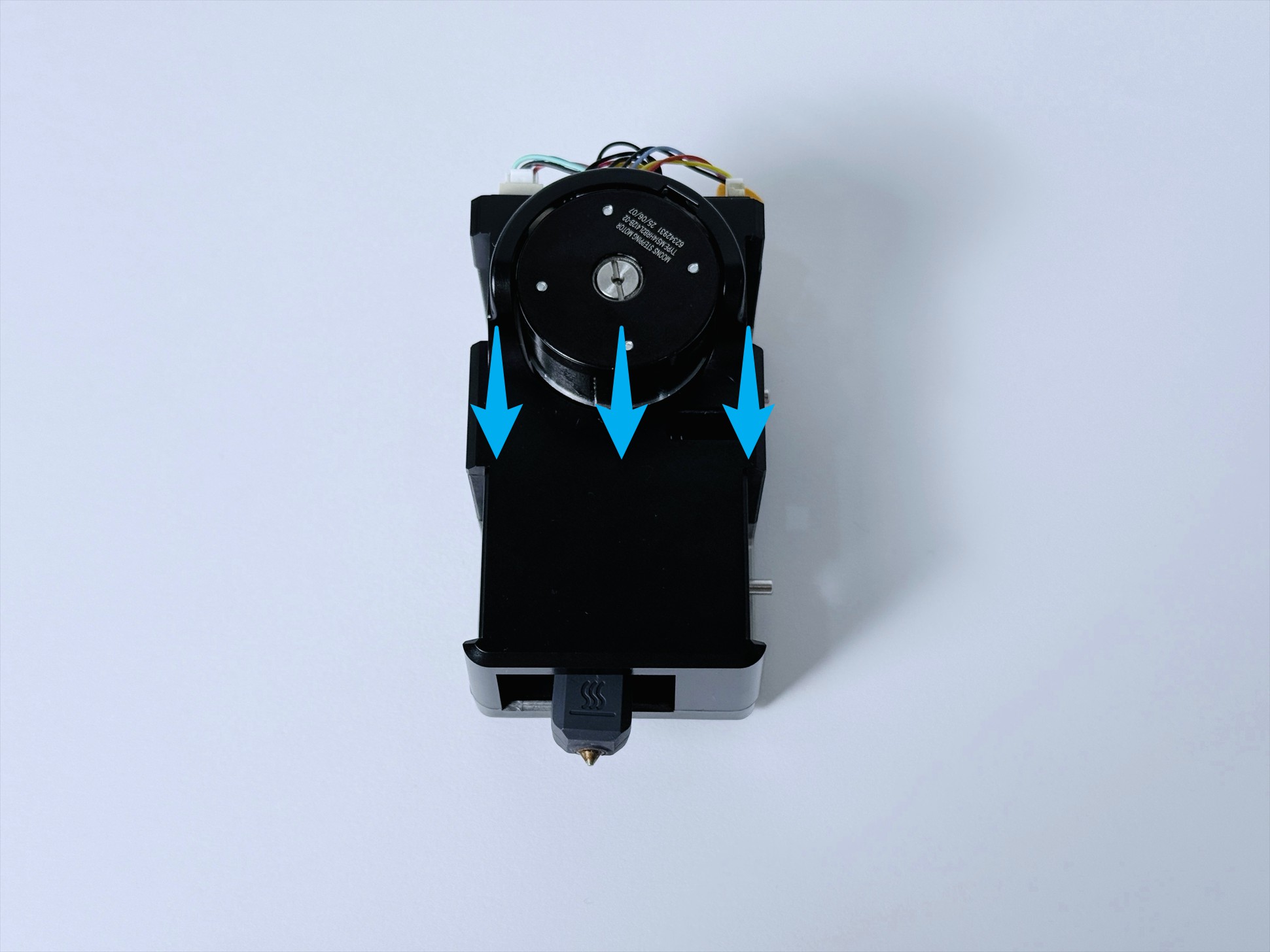
(7) Use an H1.5 hex key to remove the screws in the upper left and lower right corners.
Use an H2.0 hex key to remove the screws in the upper right and lower left corners.
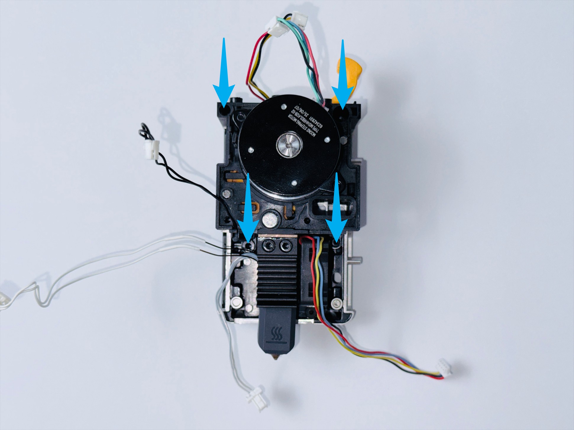
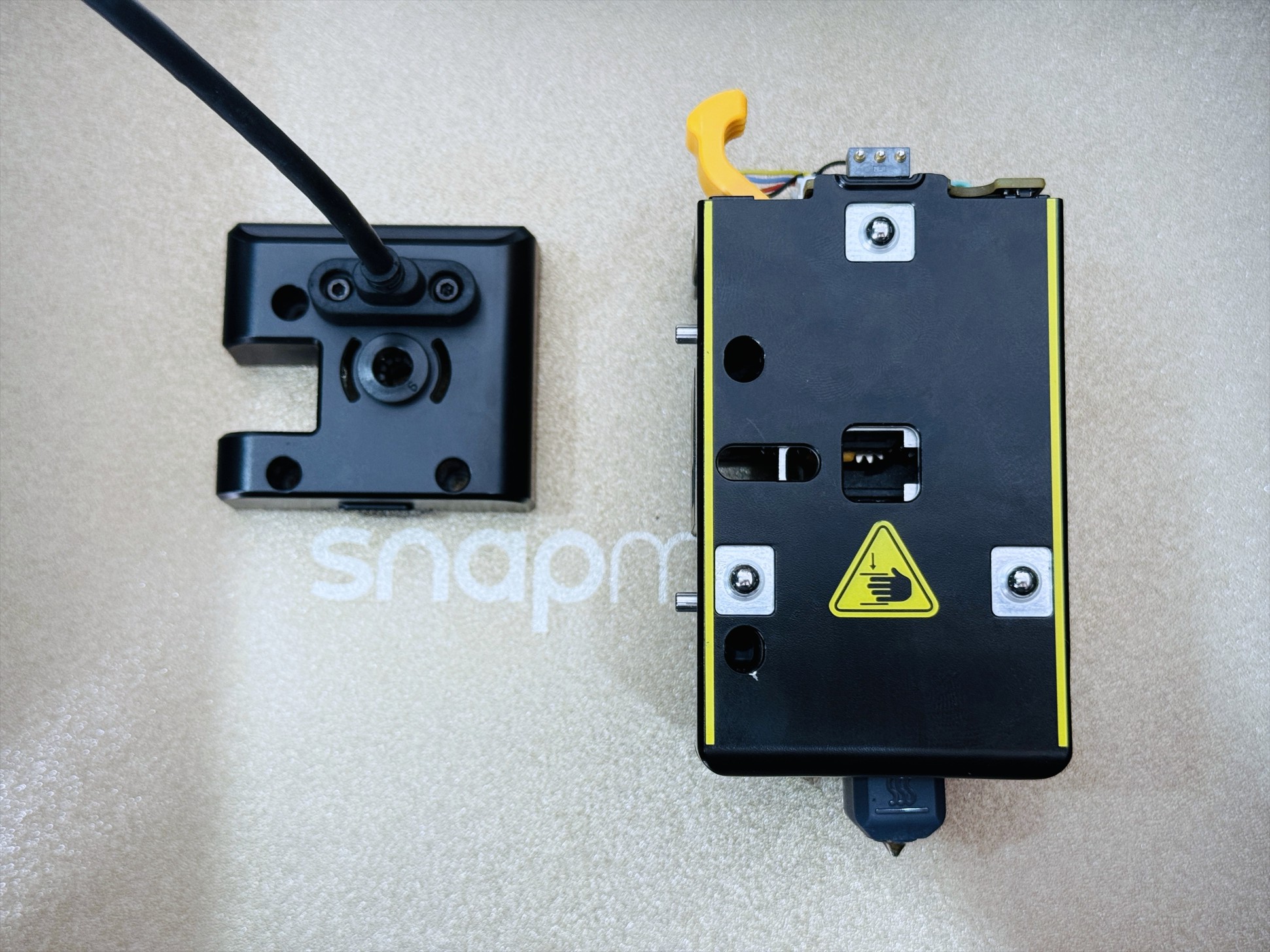
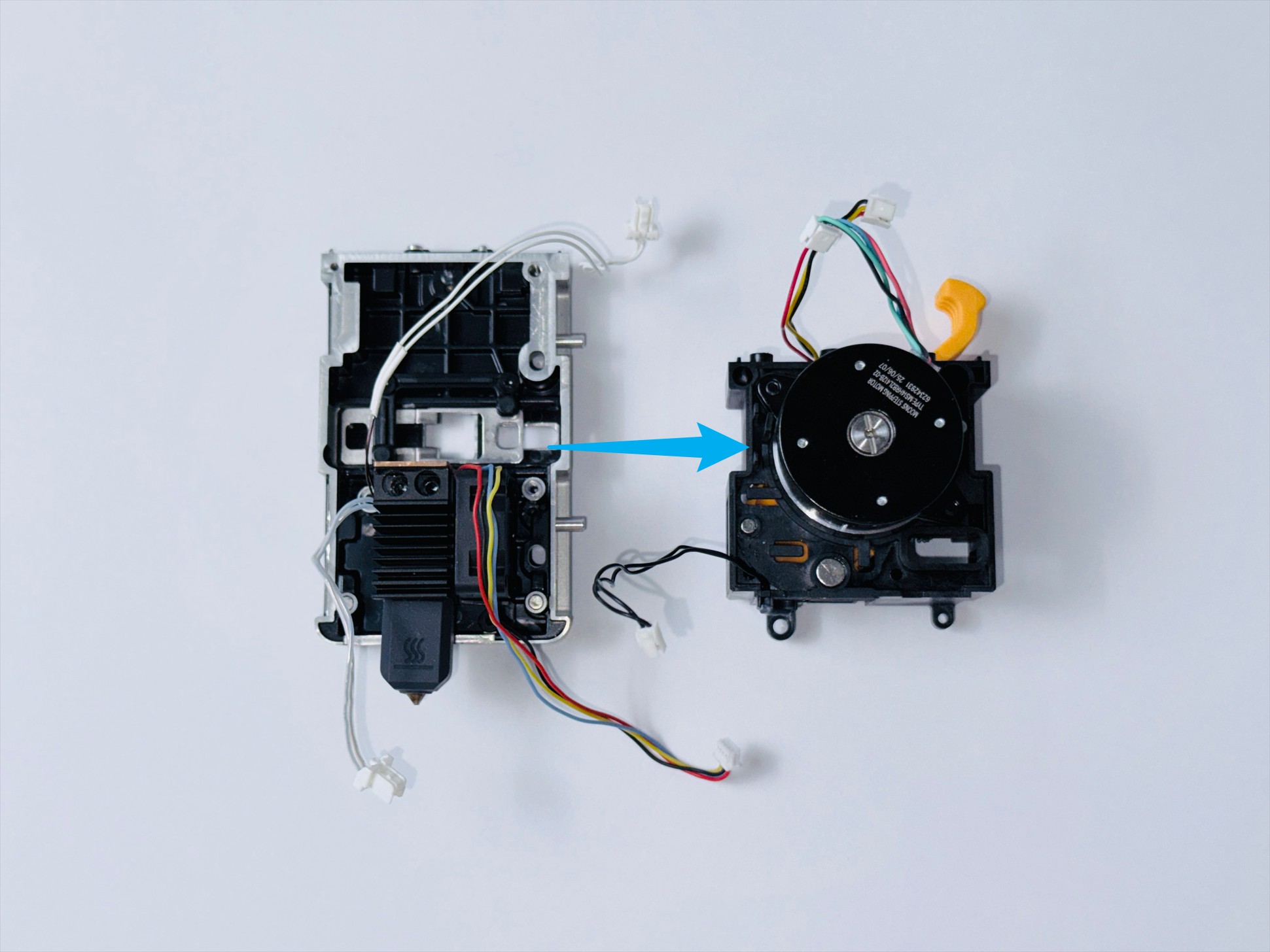
(8) Rmove the extruder unit.
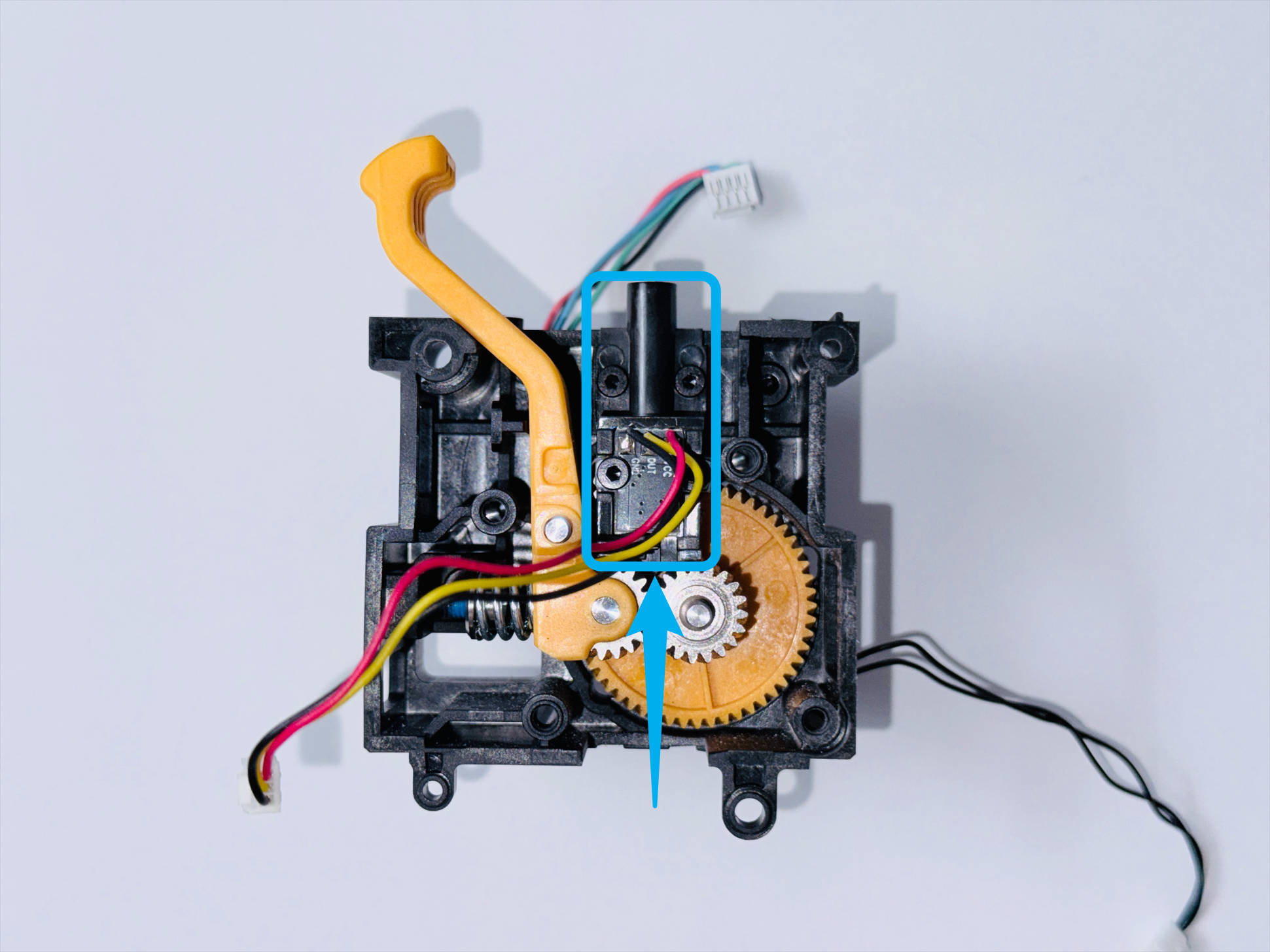
¶ Step 2 - Replace filament runout sensor
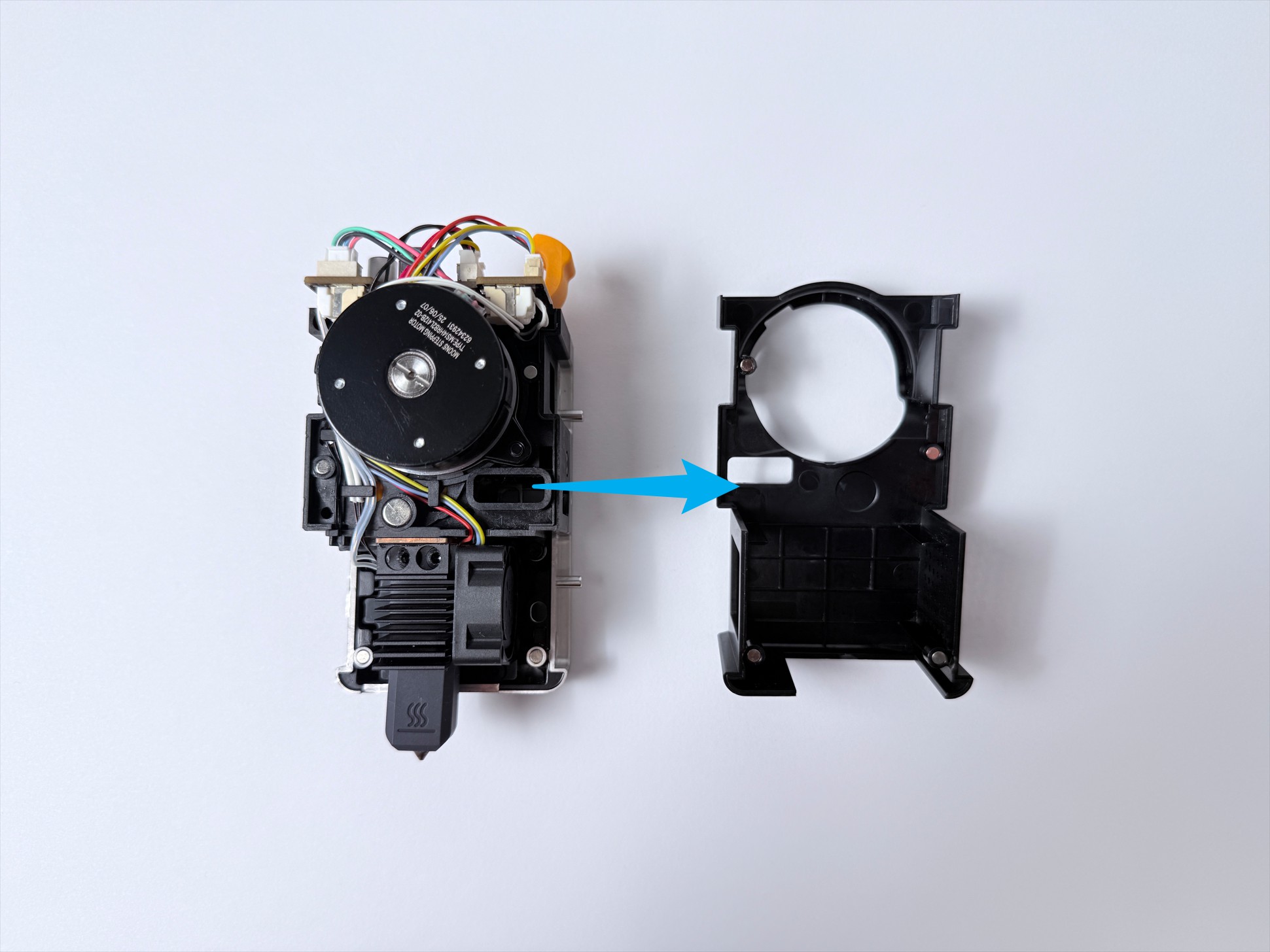
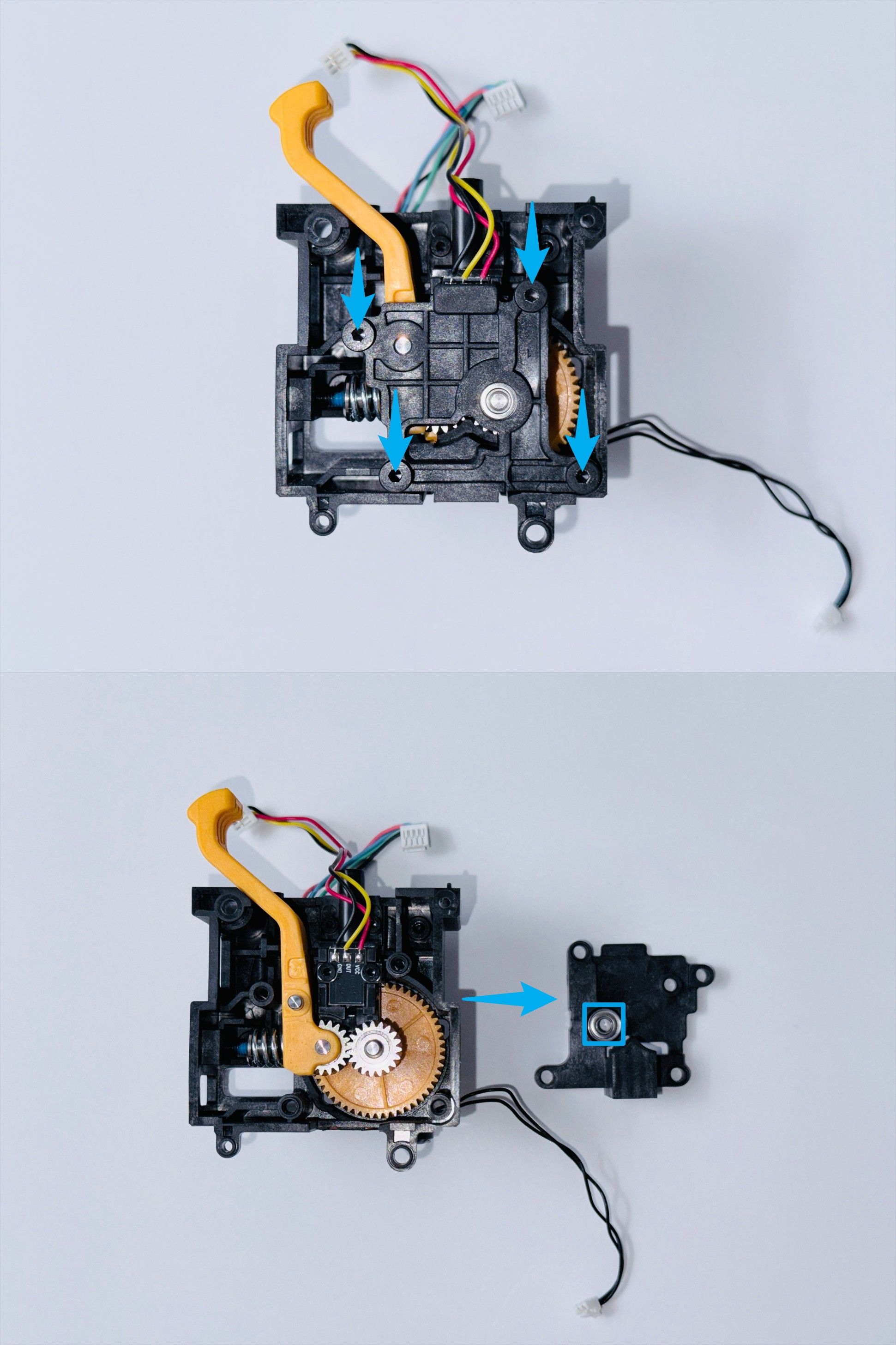
(1) Use an H2.0 hex key to remove the 4 screws, then take off the extruder bearing mount.
Note: Do not lose the bearing !
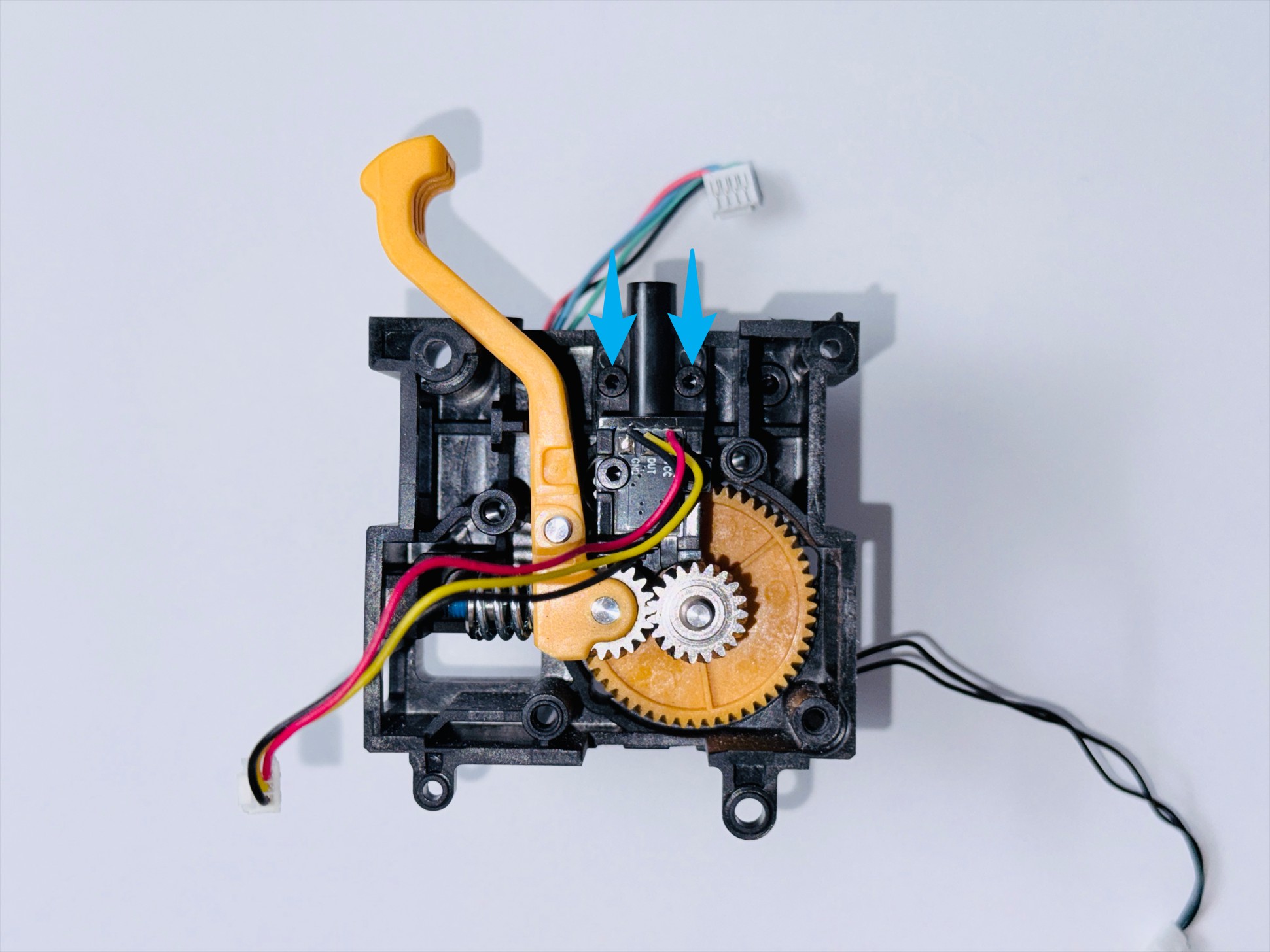
(2) Use an H1.5 hex key to remove the 2 screws, replace the filament runout sensor, and tighten the screws.
¶ Part 3 - Restore Toolhead
¶ Step 1 - Assemble toolhead
(1) Install the extruder bearing mount and use an H2.0 hex key to tighten the 4 screws.
(2) Install the extruder unit.
Use an H1.5 hex key to tighten the screws in the upper left and lower right corners;
Use an H2.0 hex key to tighten the screws in the upper right and lower left corners.
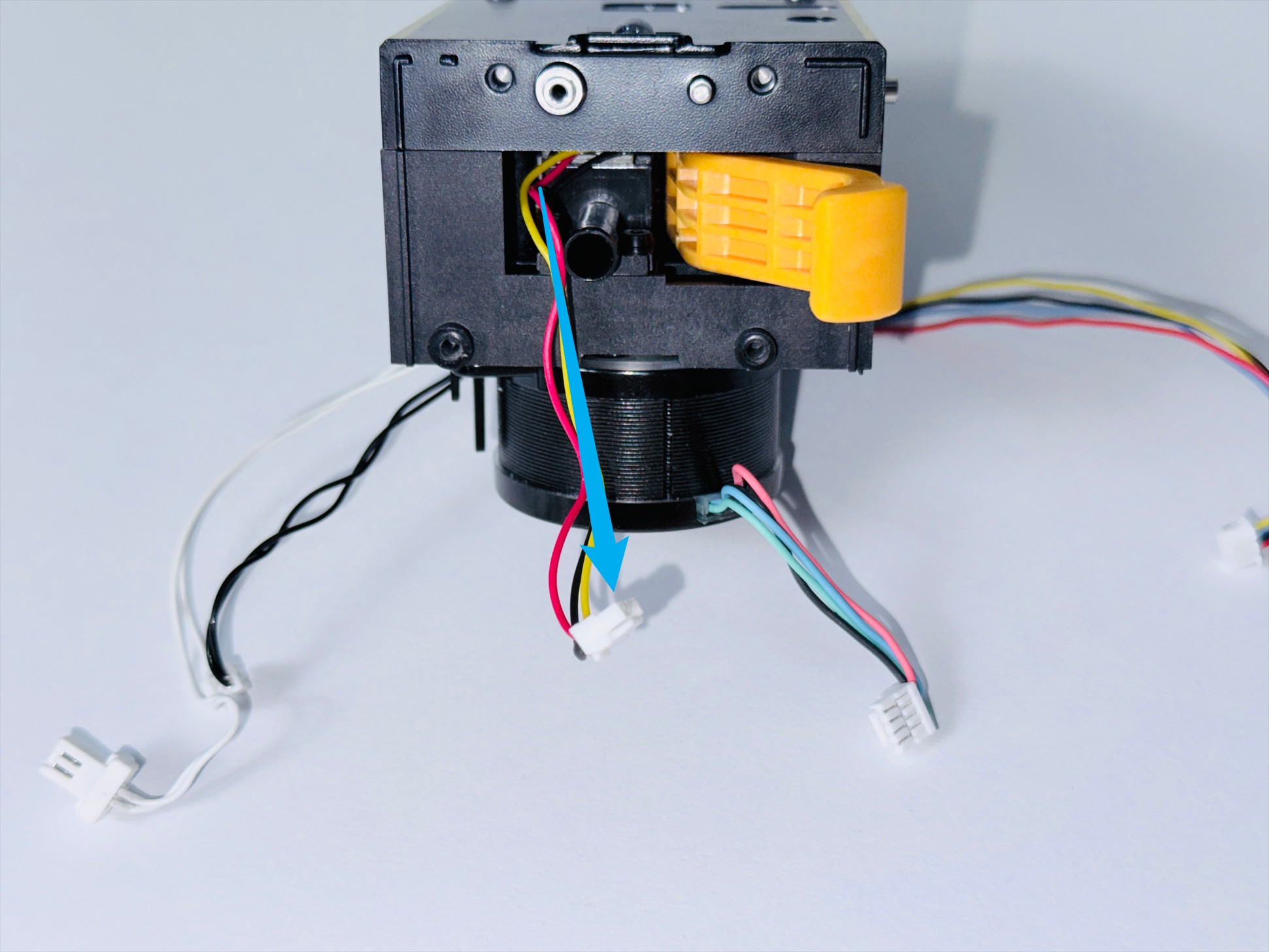
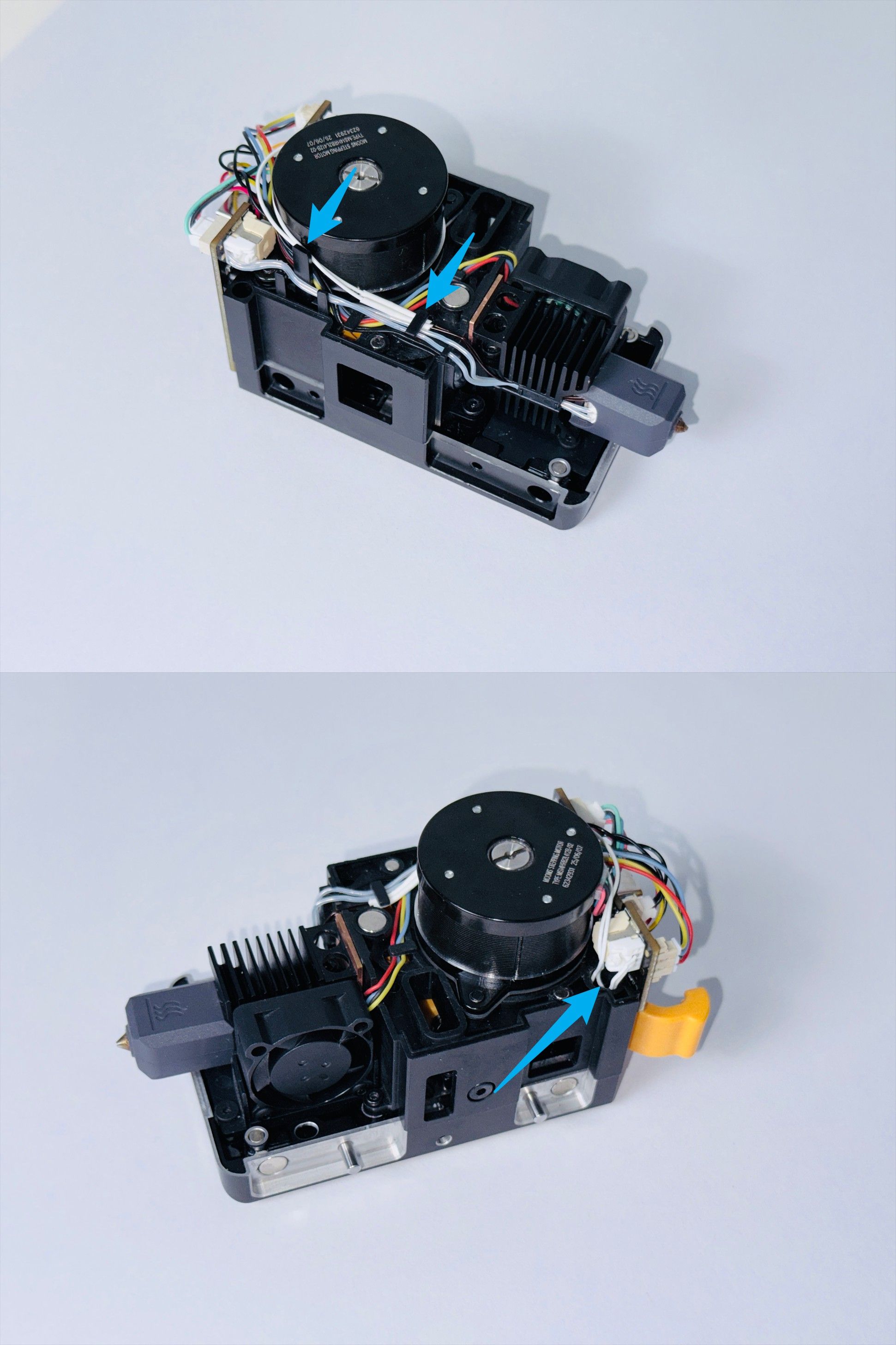
(3) Pull out the filament runout sensor cable and pay attention to the routing.
(4) Install the toolhead PCB. Use H1.5 and H2.0 hex keys to tighten the upper and lower screws.
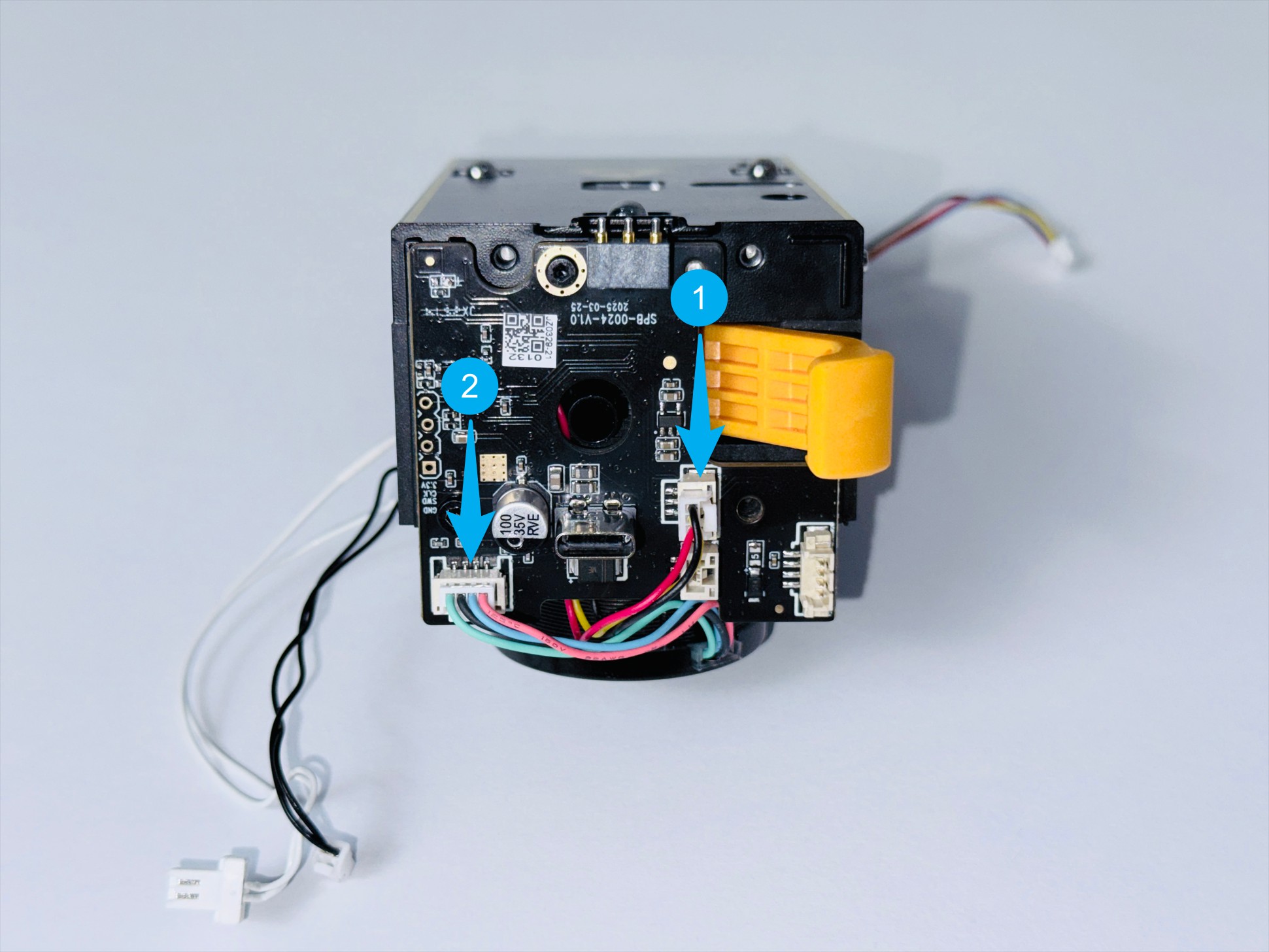
(5) Connect the filament runout sensor cable and extruder motor cable in order.
(8) Connect the hotend cooling fan cable and route it following the guide.
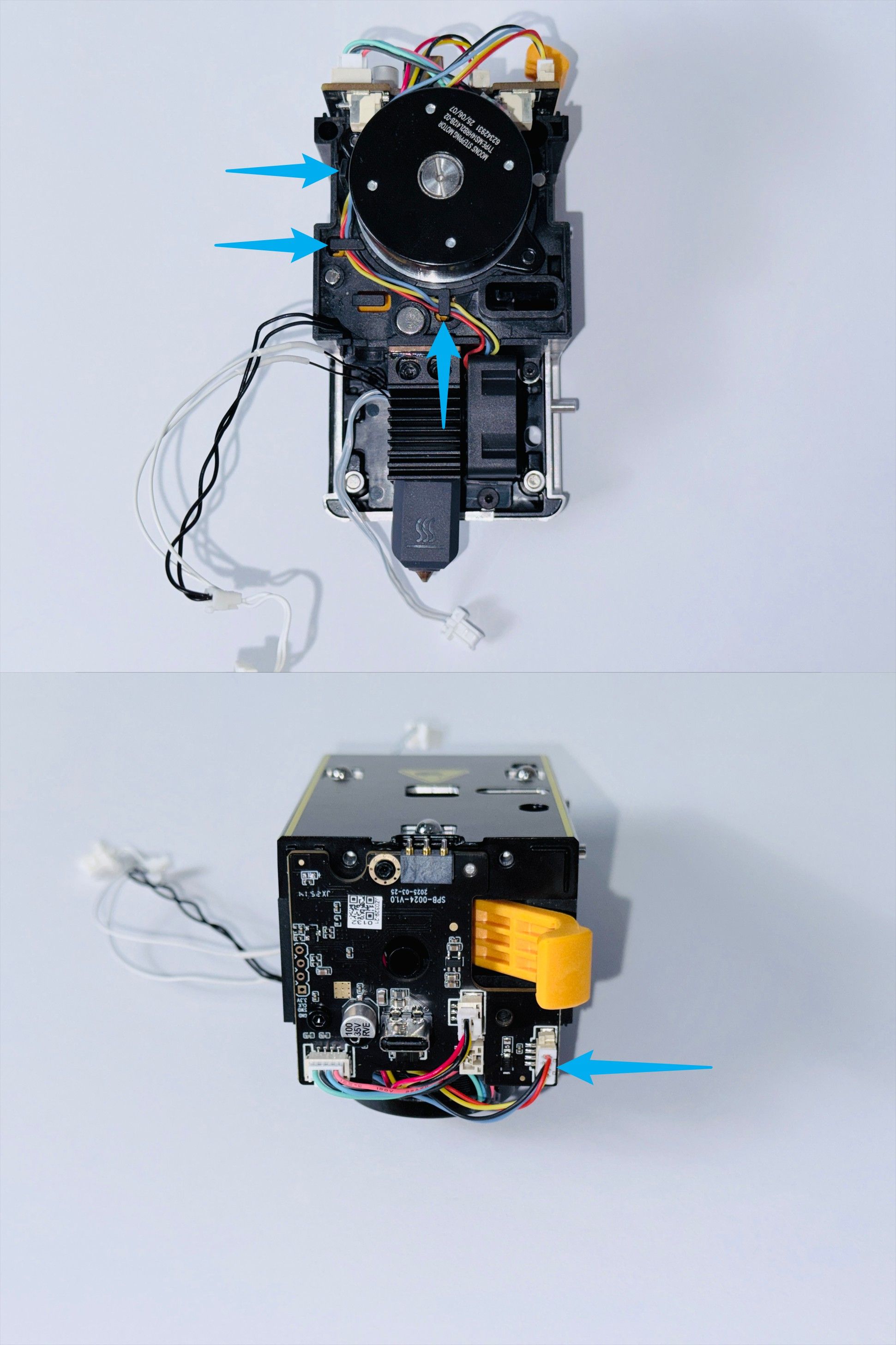
(9) Connect the calibration sensor cable and route it following the guide.
(10) Connect the ceramic heater cable and route it following the guide.
(11) Connect the thermistor cable and route it following the guide. Press any excess thermistor cable into the hole of the extruder unit.
(12) Install the toolhead rear cover.
¶ Step 2 - Park toolhead
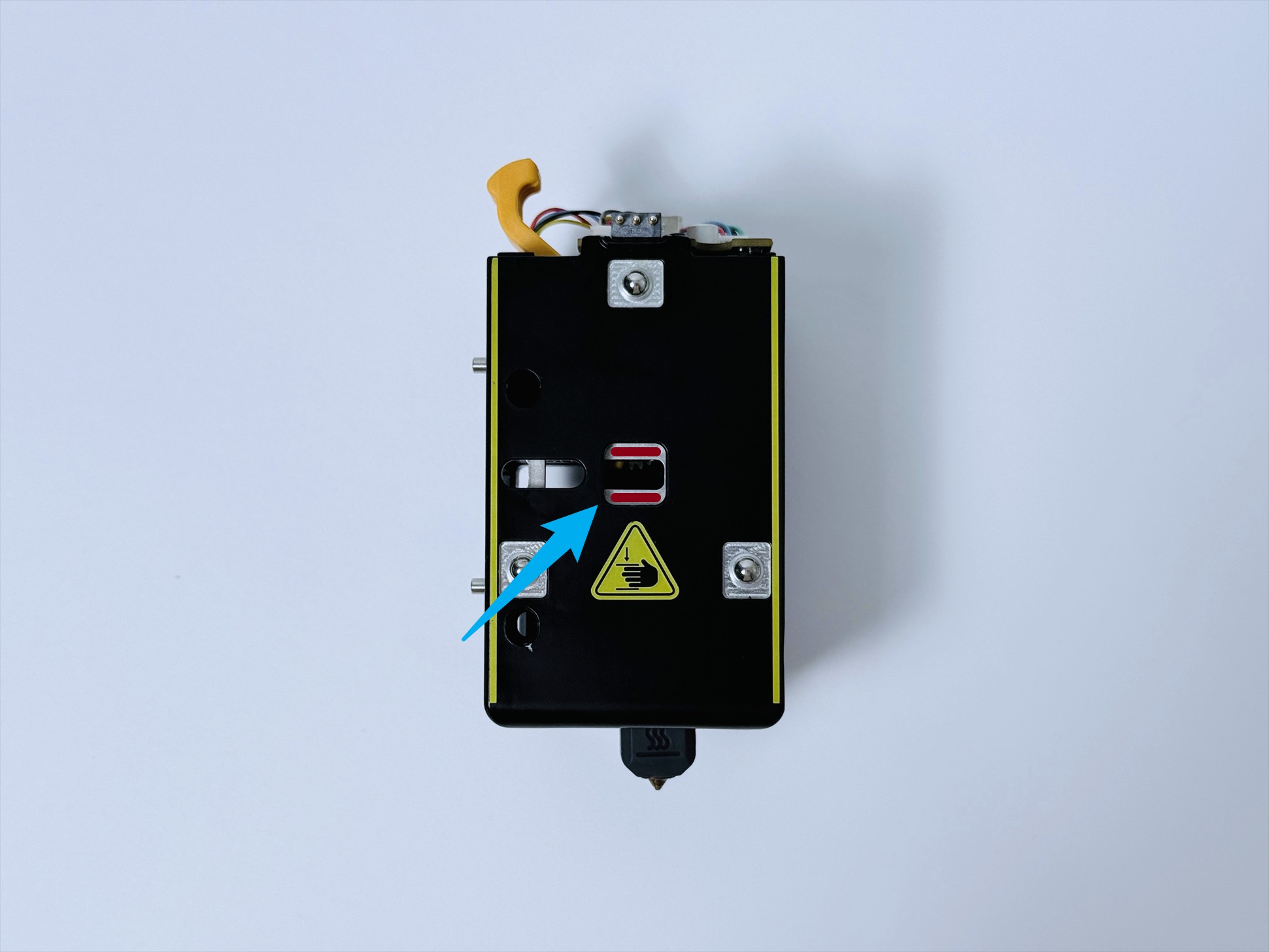
(1) Use an H2.0 hex key to adjust the latch position until both red marks are fully visible.
(2) Place the toolhead back onto the parking bracket.
(3) Connect the toolhead cable and install the toolhead top cover.
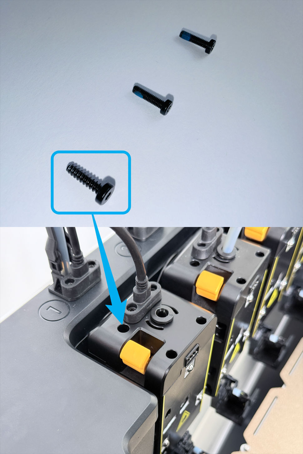
(4) Tighten the 3 screws with an H2.0 hex key.
Note: 1 screw is different and should be installed at the marked position.
(5) Insert the filament tube.
¶ Reach out to Snapmaker Support
Should you experience any difficulties while following the replacement instructions above, or if you have any suggestions to share, we warmly invite you to submit a ticket at: https://snapmaker.formcrafts.com/u1-troubleshooting-request
Our dedicated support team will be more than willing to assist you in resolving the issue.