Video tutorial available!
A video version of this replacement guide is also available. If you find the video more helpful, you can watch it here:
¶ Overview
¶ Location
The ceramic heater and thermistor are located on the heating block of hot end. To replace them, the hot end must be removed.
¶ Terminology
Different from our official term, some people may use the following terms to describe this component:
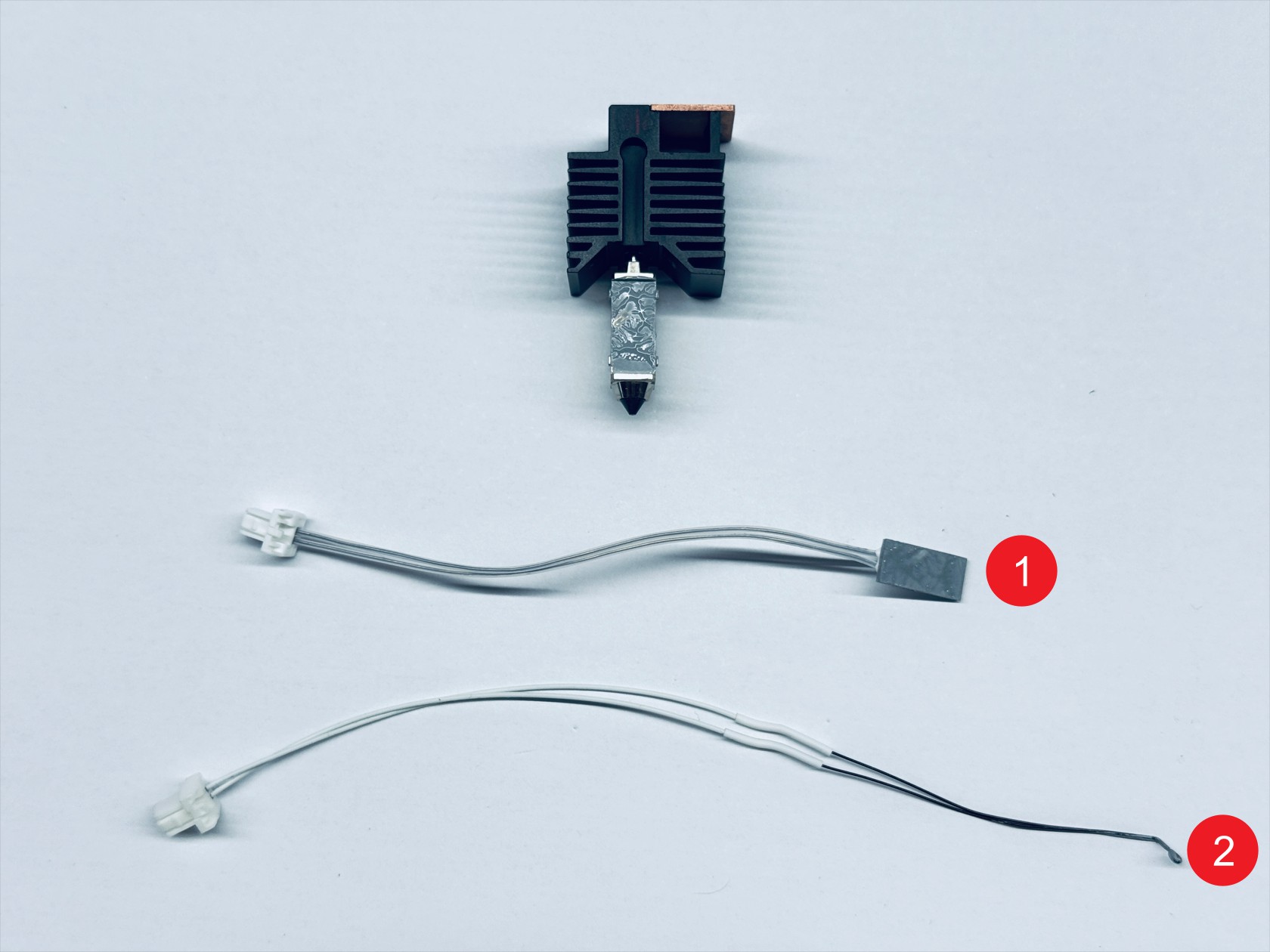
(1) Heater core
(2) Hotend heater
(3) Heater wire
(4) Heater module
¶ Complexity
Difficulty:★★☆☆☆ (Easy)
Estimated Time:15 minutes
¶ Where to Buy
Ceramic heater:
Thermistor:
¶ Tools and Parts Required
(1) H2.0 hex key
(2) New ceramic heater and thermistor
¶ Procedure
¶ Step 1. Unload filament
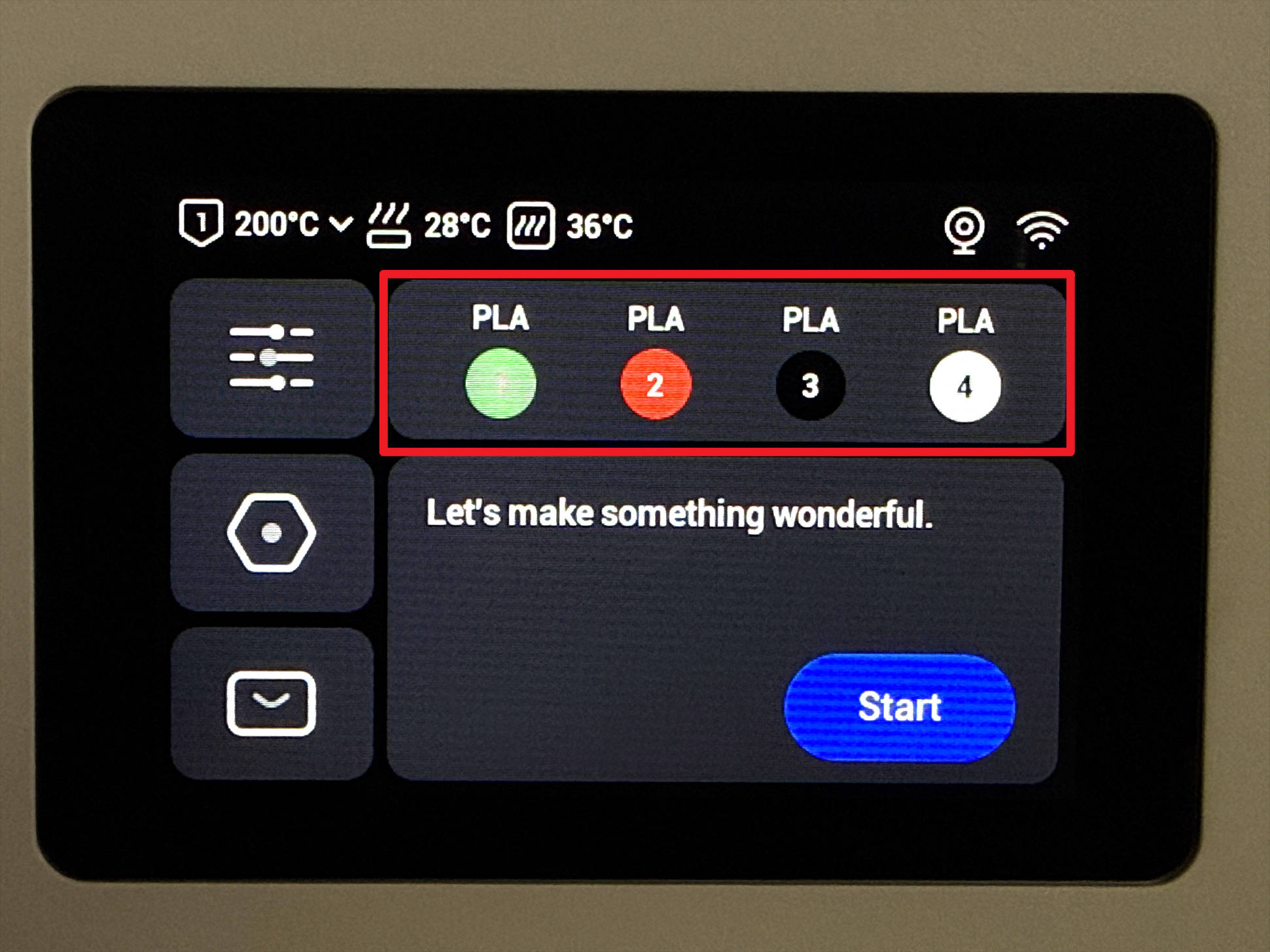
(1) Tap the filament info section on the home page.
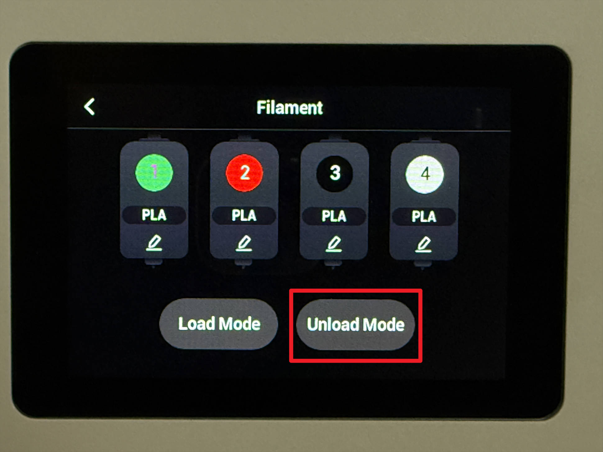
(2) Tap "Unload mode".
(3) Choose the target toolhead (e.g., Toolhead 1) and tap "Unload".
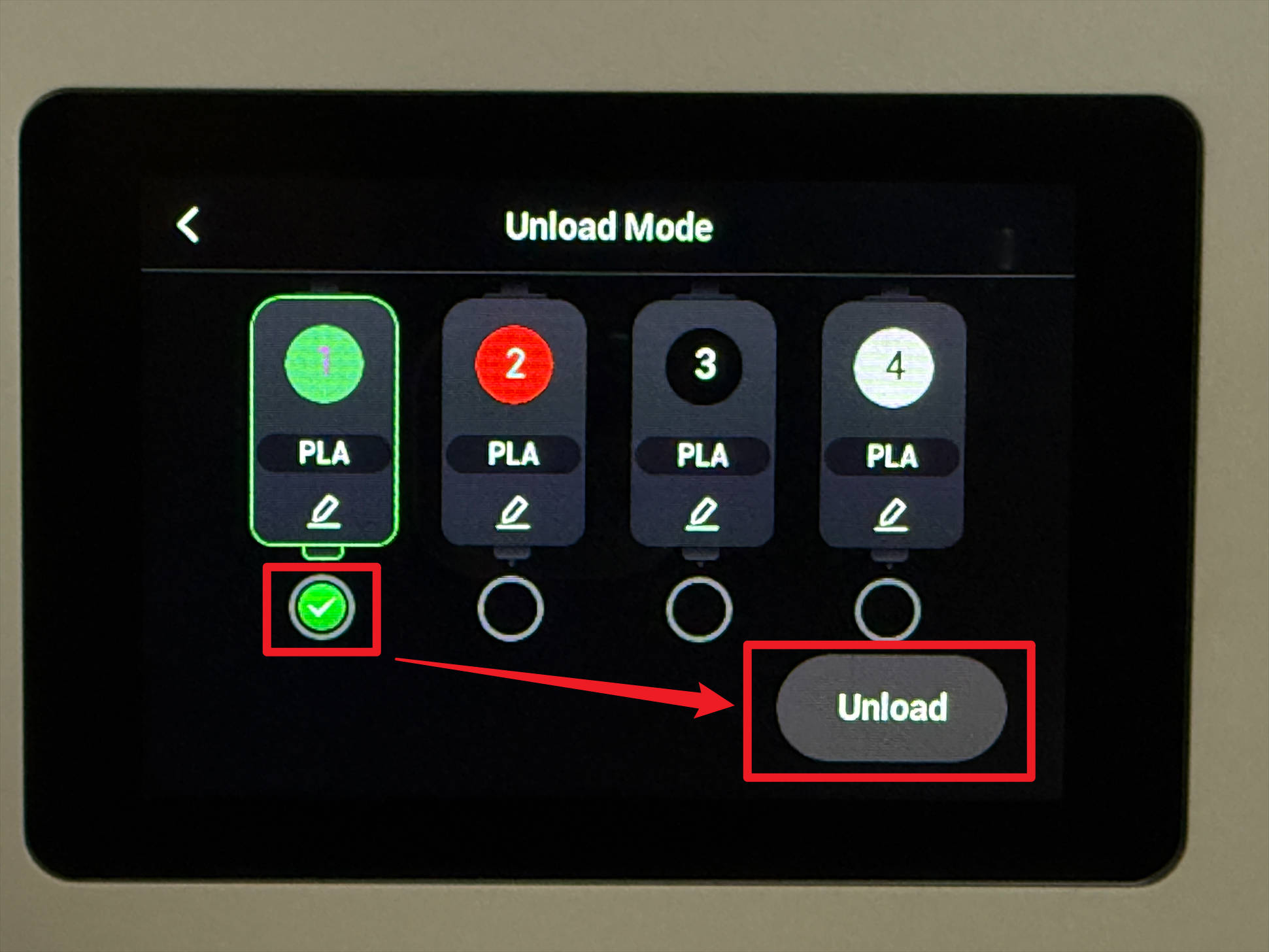
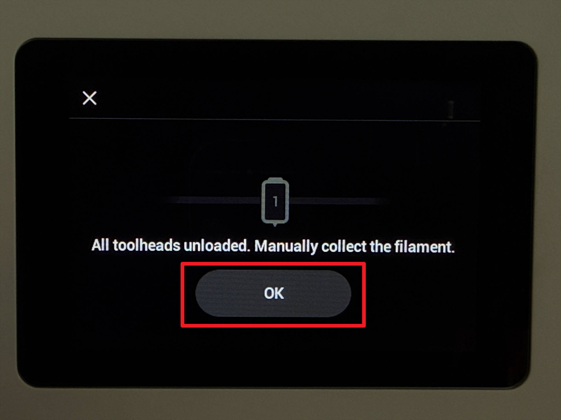
(4) Wait for the printer to finish unloading, then tap "OK".
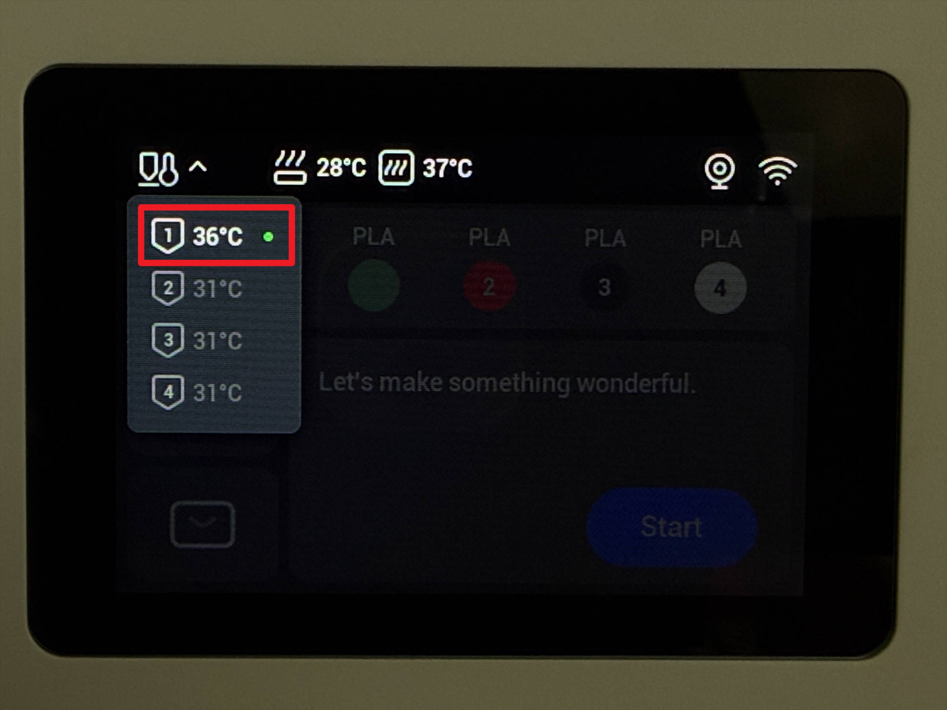
(5) Return to the home page, tap the upper-left corner to check the nozzle temperature, and wait until it cools below 40 °C.
¶ Step 2. Remove the hot end
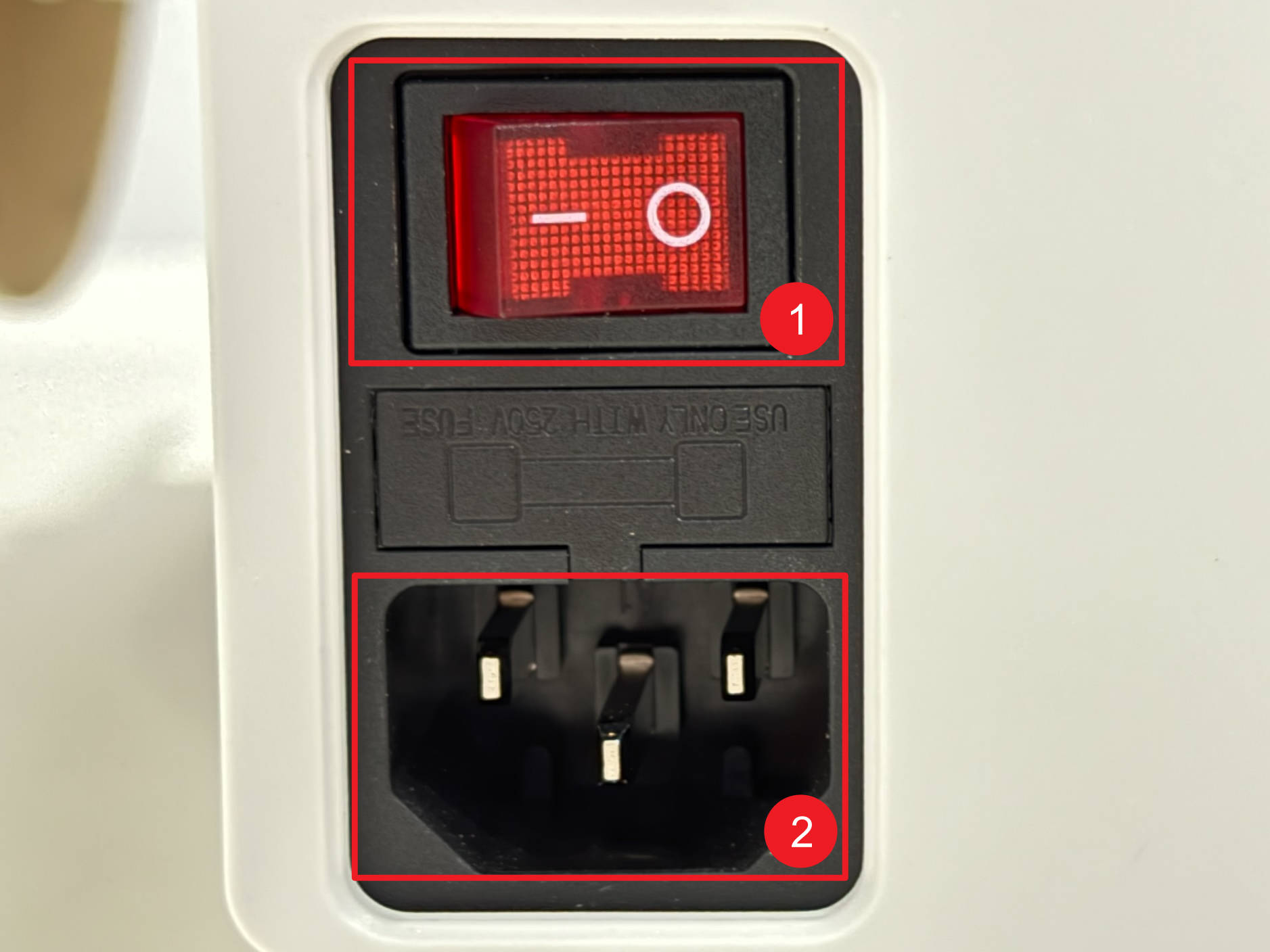
Before continuing, please power off the machine and unplug it!
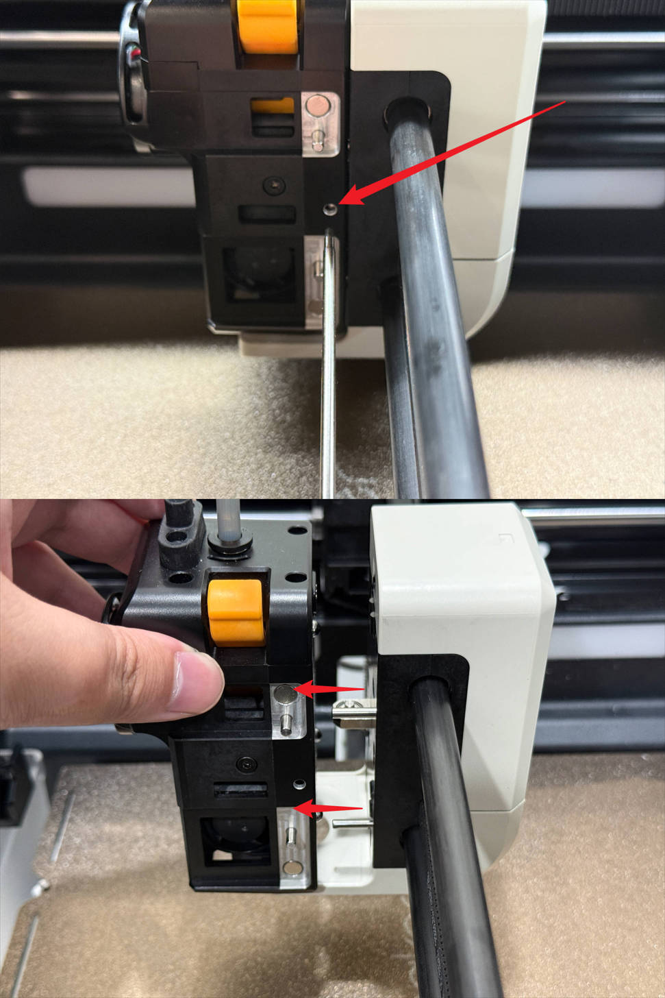
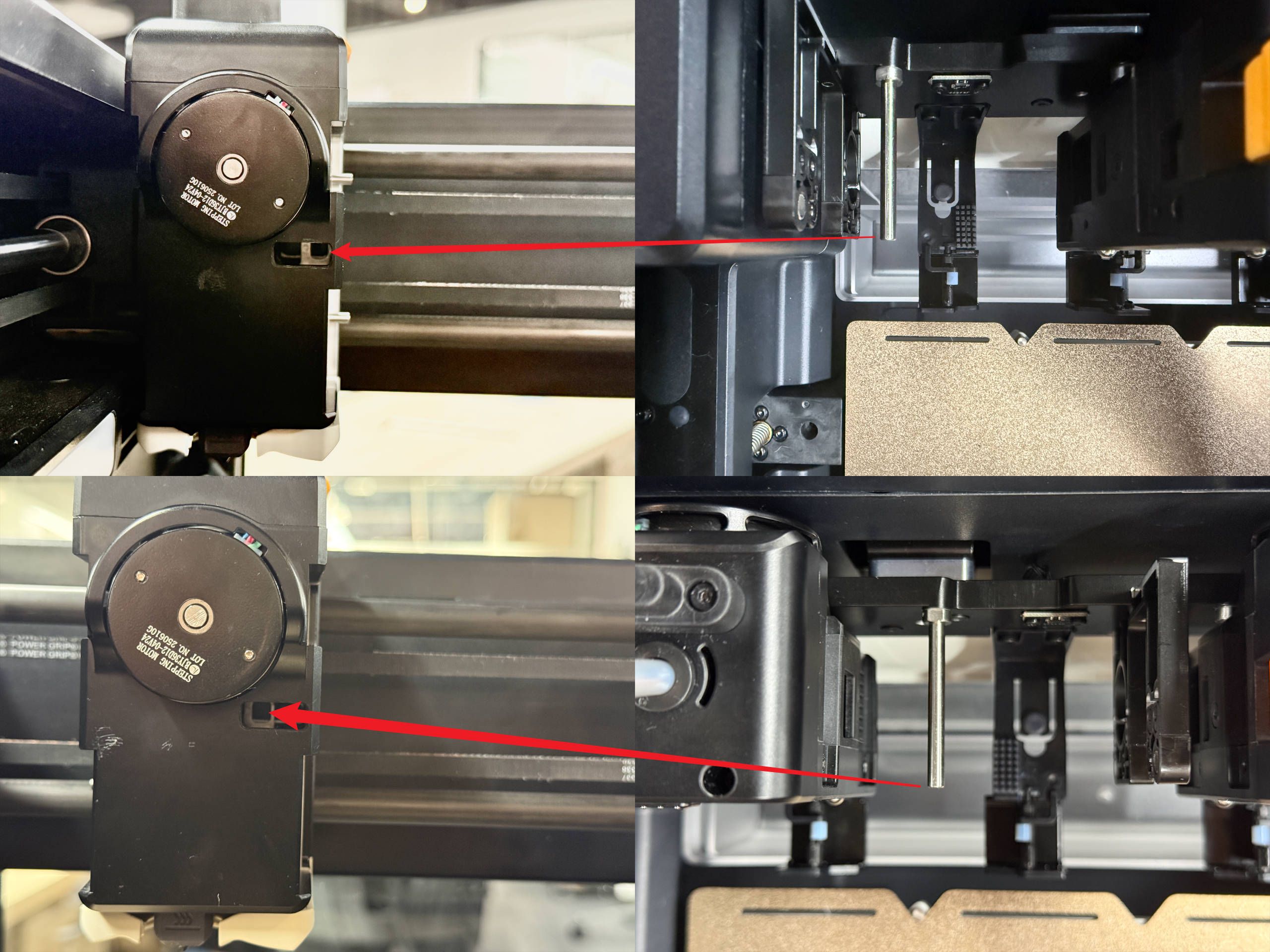
(1) Insert an H2.0 hex key into the center hole between the 2 locating pins. Push until you hear a click sound to detach the toolhead from the swapper.
(2) Remove the toolhead rear cover.
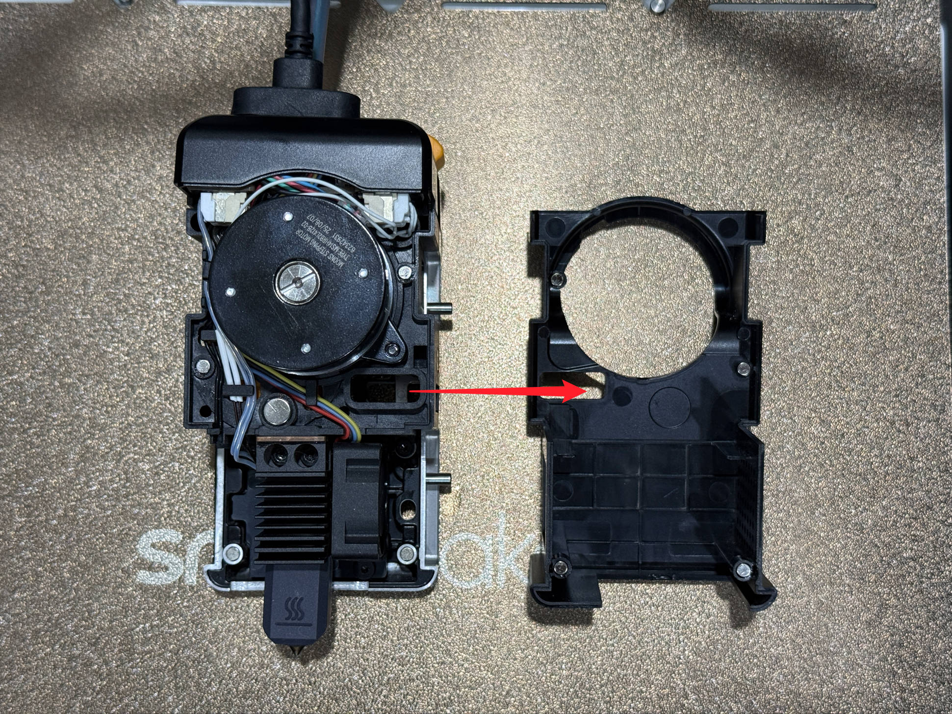
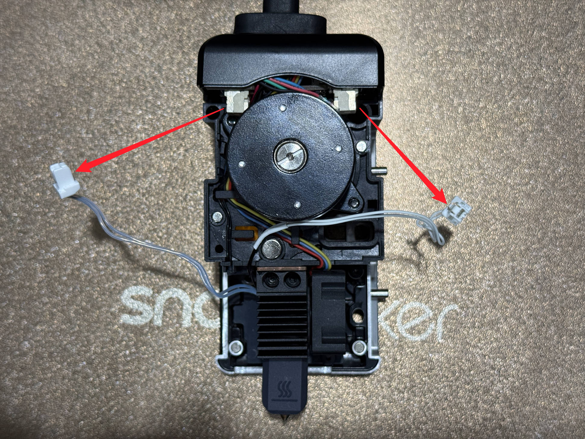
(3) Disconnect the hot end cables. You can press the locking clip with the H2.0 hex key to release it.
(4) Remove the 2 screws with an H2.0 hex key and detach the hot end.
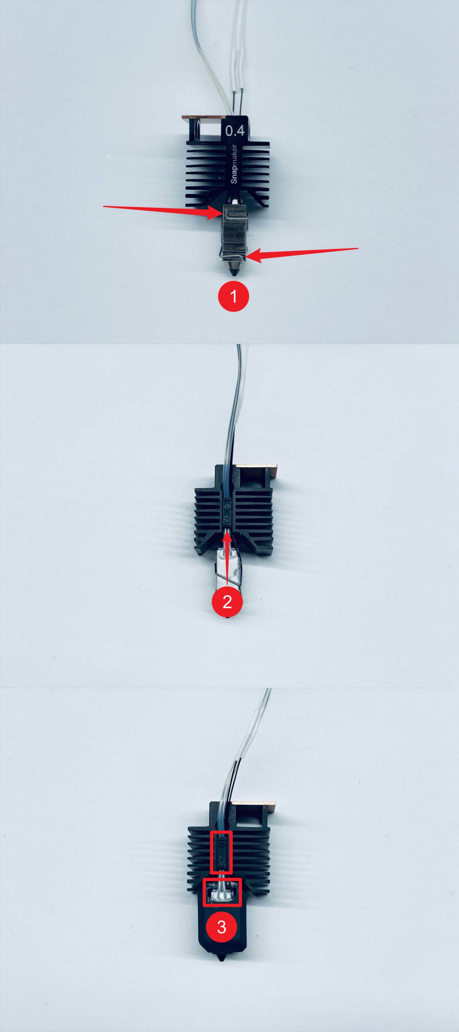
¶ Step 3. Replace the ceramic heater and thermistor
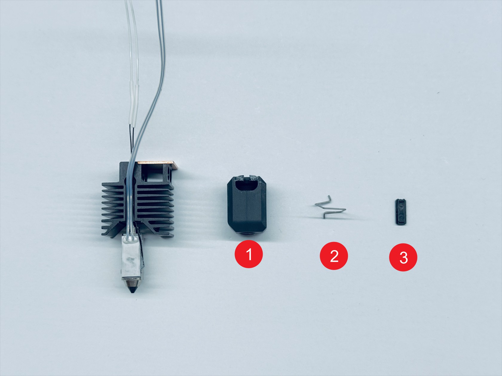
(1) Remove the following parts in order:
-
1: Hot end silicone sock
-
2: Ceramic heater clamp spring
-
3: Hot end wire press strip
(2) Remove the old ceramic heater and thermistor in order.
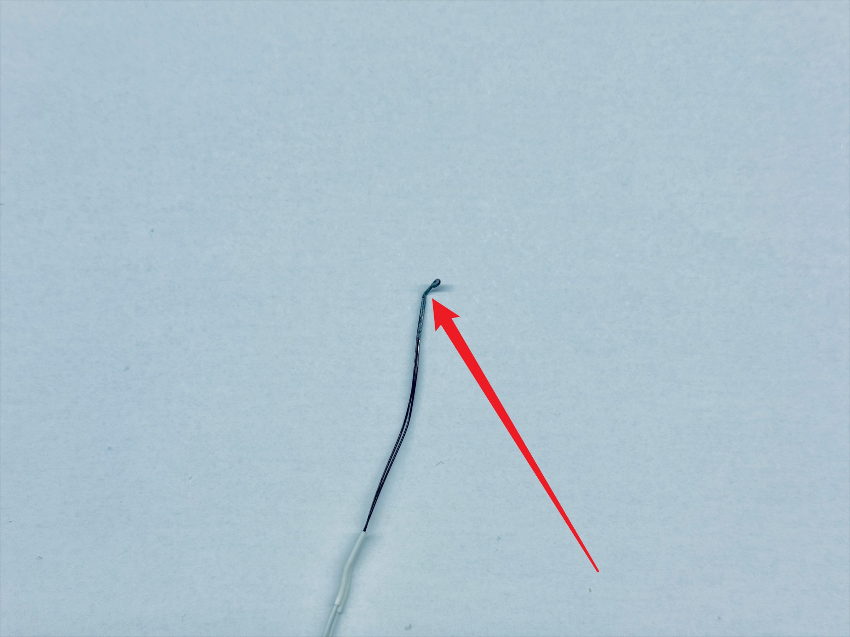
(3) Bend the front end of the new thermistor 90°.
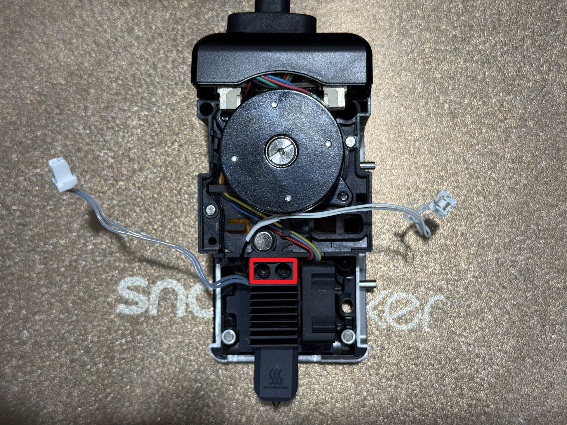
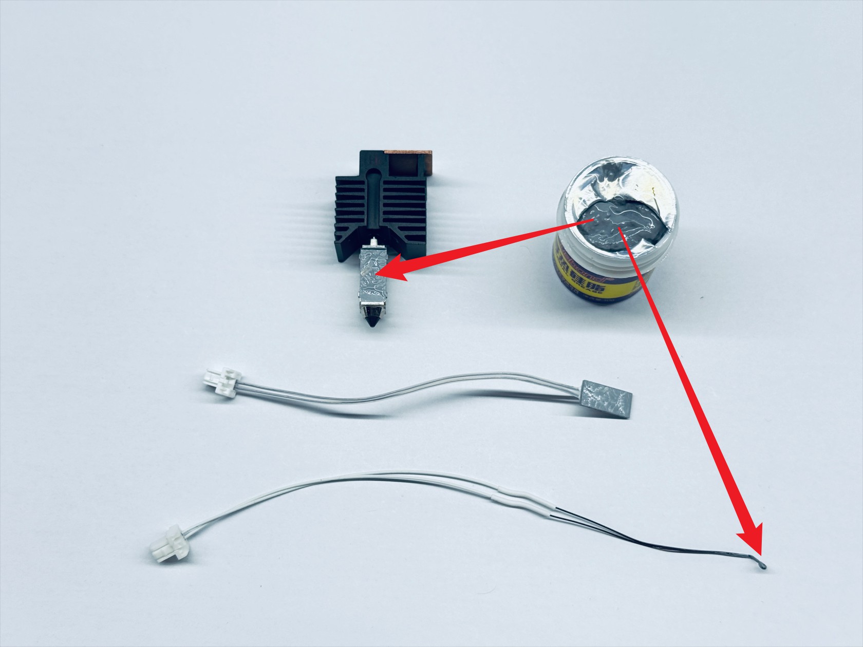
(4) Dip the thermistor probe in an appropriate amount of thermal grease, then evenly apply thermal grease to the ceramic heater mounting area.
(5) Install the new ceramic heater and thermistor.
(6) Reinstall the heater clamp spring, then install the wire press strip and the silicone sock (make sure the silicone sock notch faces the same direction as the wire press strip).
¶ Step 4. Reinstall the hot end
(1) Mount the hot end back in place and tighten the 2 screws with an H2.0 hex key.
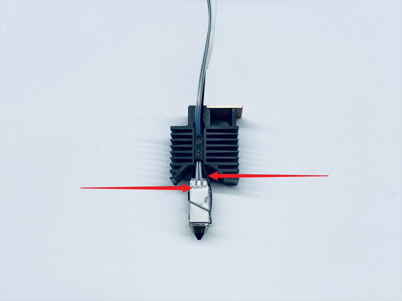
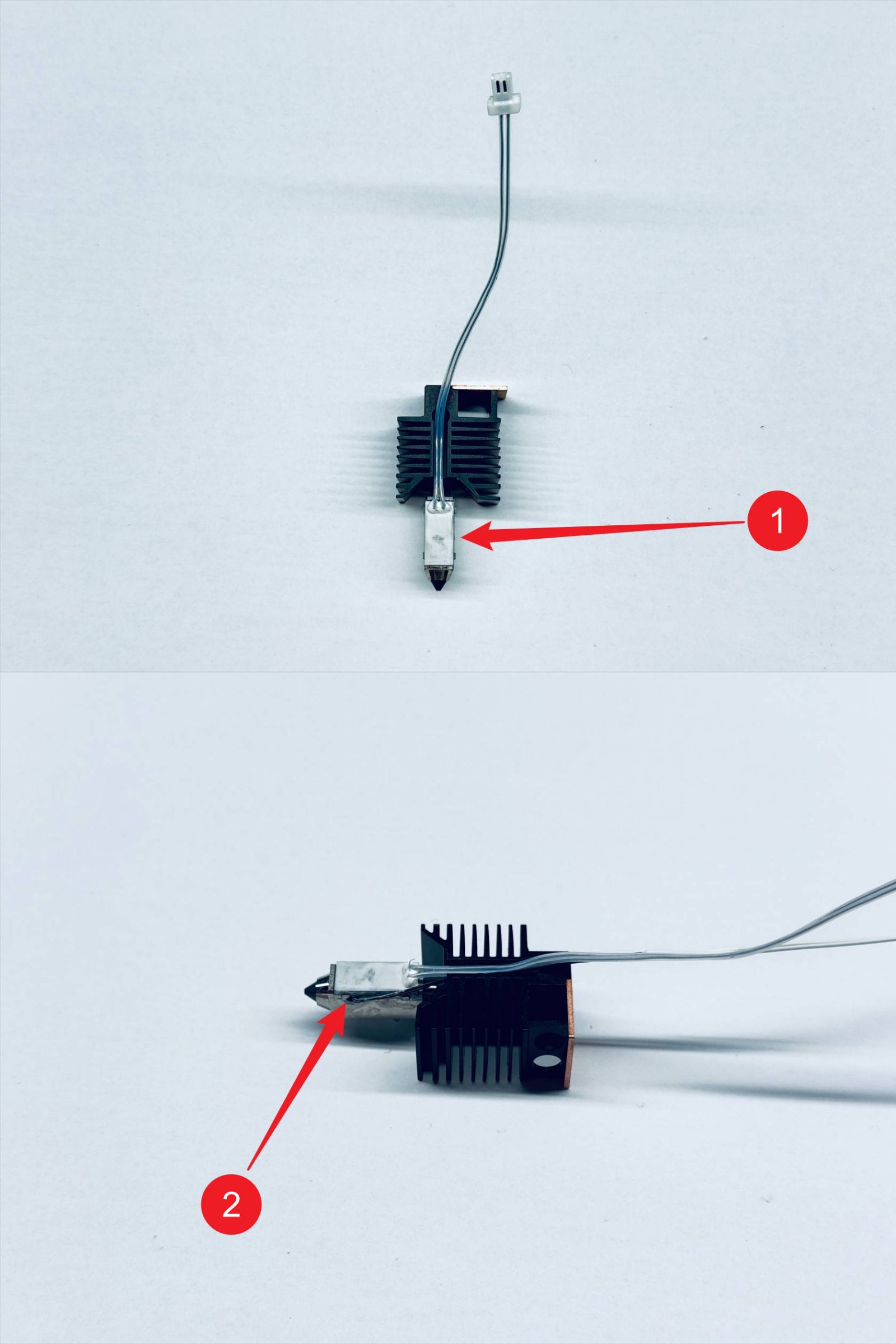
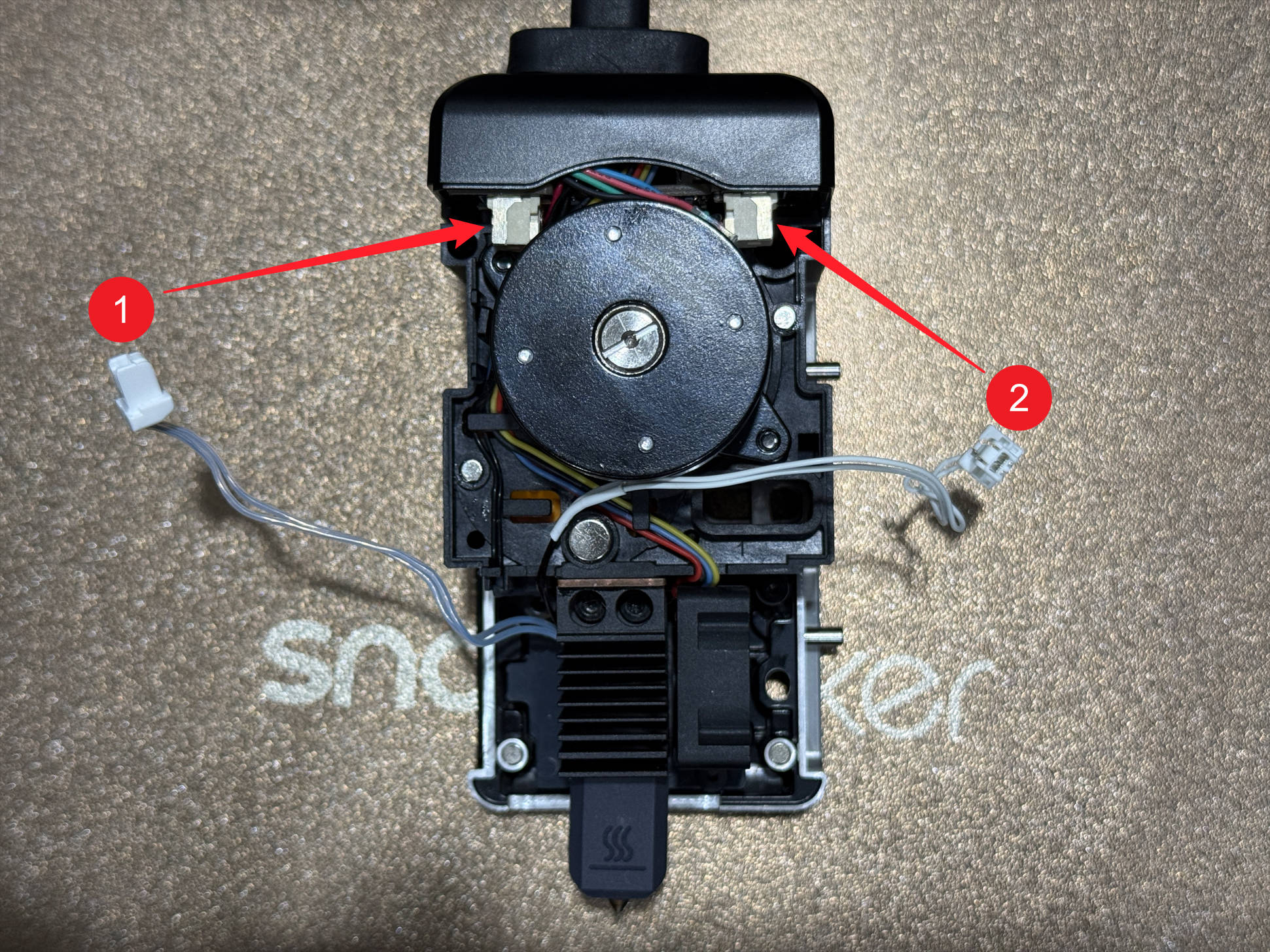
(2) Reconnect the cables:
- 1 – Ceramic heater cable (left port)
- 2 – Thermistor cable (right port)
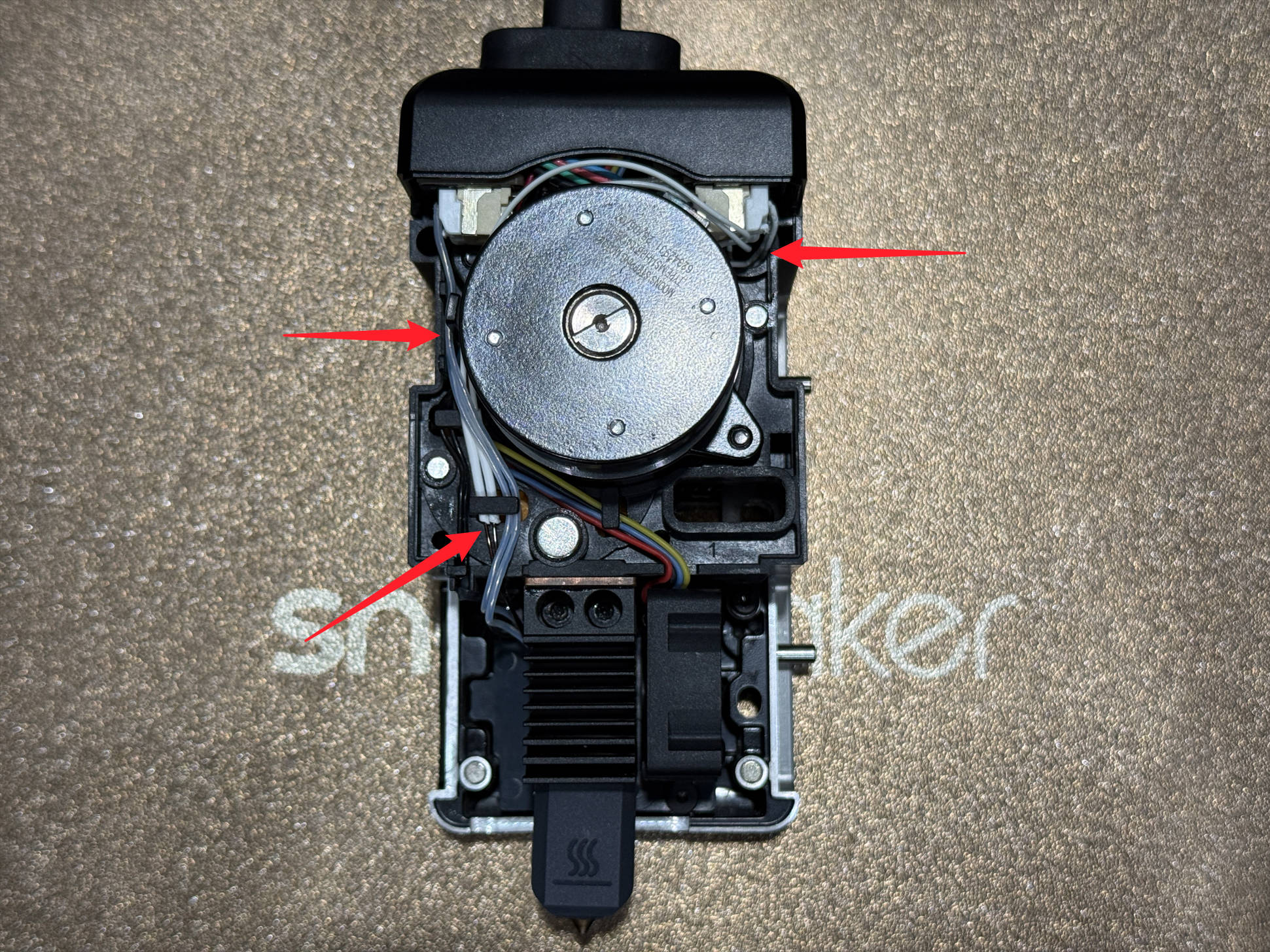
(3) Route the cables properly: press both into the cable clip, and fold the thermistor cable end before pressing it into the extruder unit slot.
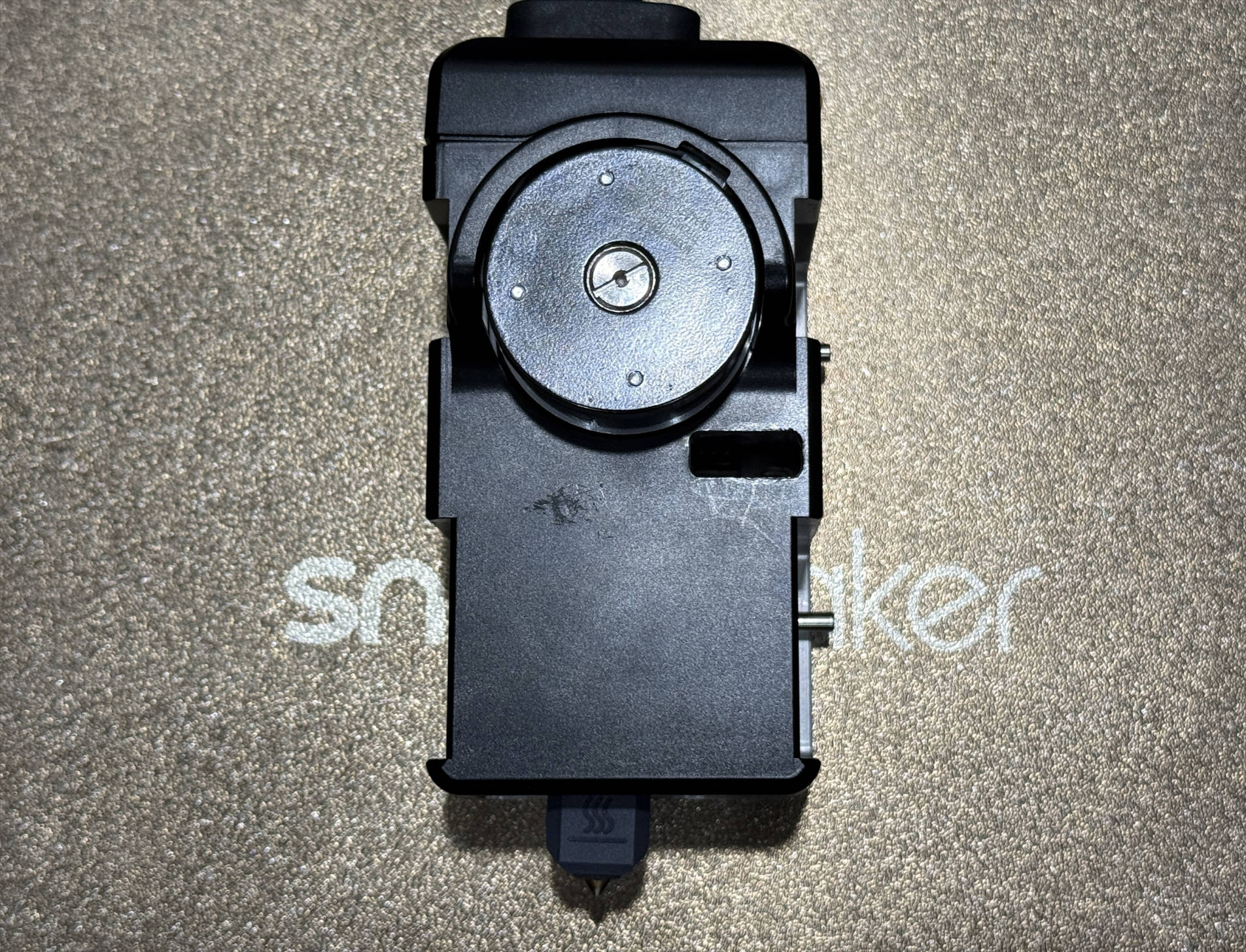
(4) Reinstall the toolhead rear cover.
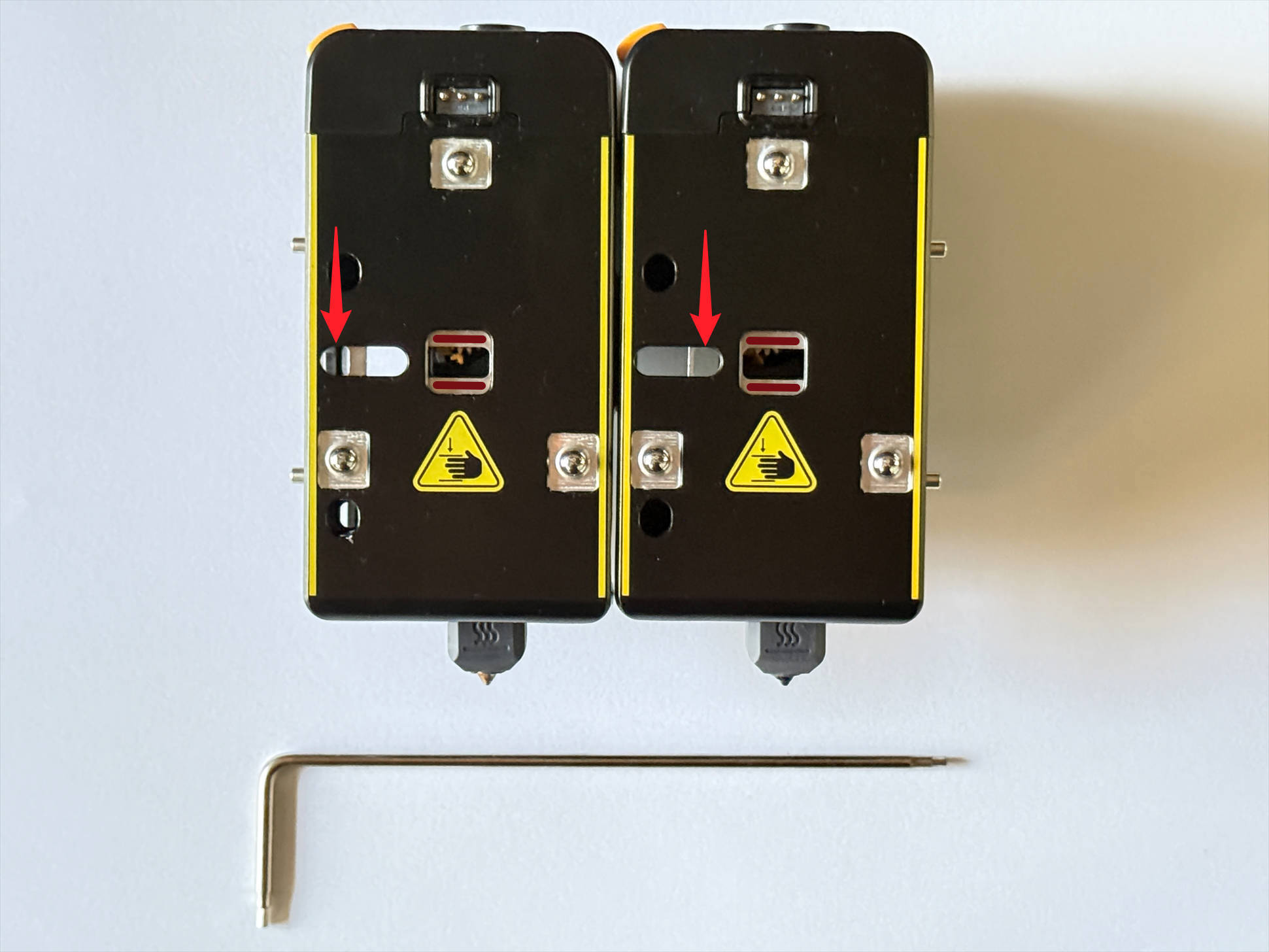
¶ Step 5. Park toolhead
(1) Use an H2.0 hex key to adjust the toolhead latch until two red markings are visible.
- Left:Toolhead 1 – latch to the left limit
- Right:Toolhead 2/3/4 – latch to the right limit
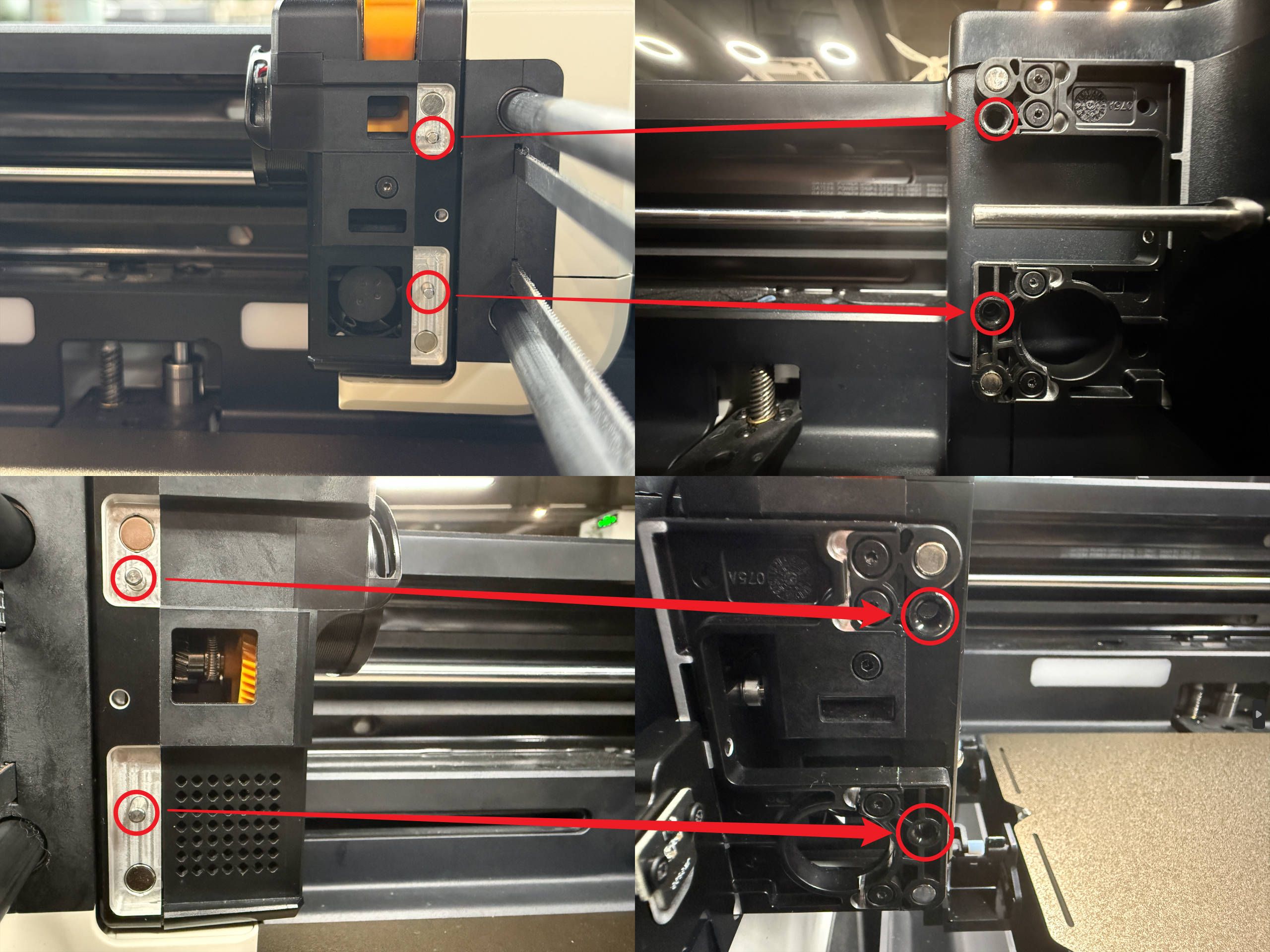
(2) Align the latch hole with the locating pin on the swapper and push the toolhead inward until it stops.
(3) Keep pushing inward and move the toolhead slightly so the 2 side locating pins fit into the bracket holes.
¶ Reach out to Snapmaker Support
After following the troubleshooting steps, if you find it difficult to resolve your issue, kindly submit a support ticket through https://snapmaker.formcrafts.com/u1-troubleshooting-request and share your troubleshooting results with some pictures/videos.
Our dedicated support team will be more than willing to assist you in resolving the issue.