¶ Overview
¶ Location
The active extruder gear assembly is located inside the extruder unit. To access the active extruder gear assembly for replacement, the extruder unit must be removed and disassembled.
¶ Difficulty and Time Estimate
- Difficulty:★★☆☆☆ (Easy)
- Estimated Time:20 minutes
¶ Where to Buy
This accessory is expected to be available on the official Snapmaker online store soon. Please stay tuned.
¶ Tools and Parts Required
- H1.5 hex key
- H2.0 hex key
- New active extruder gear assembly
¶ Procedure
¶ Step 1. Remove the toolhead
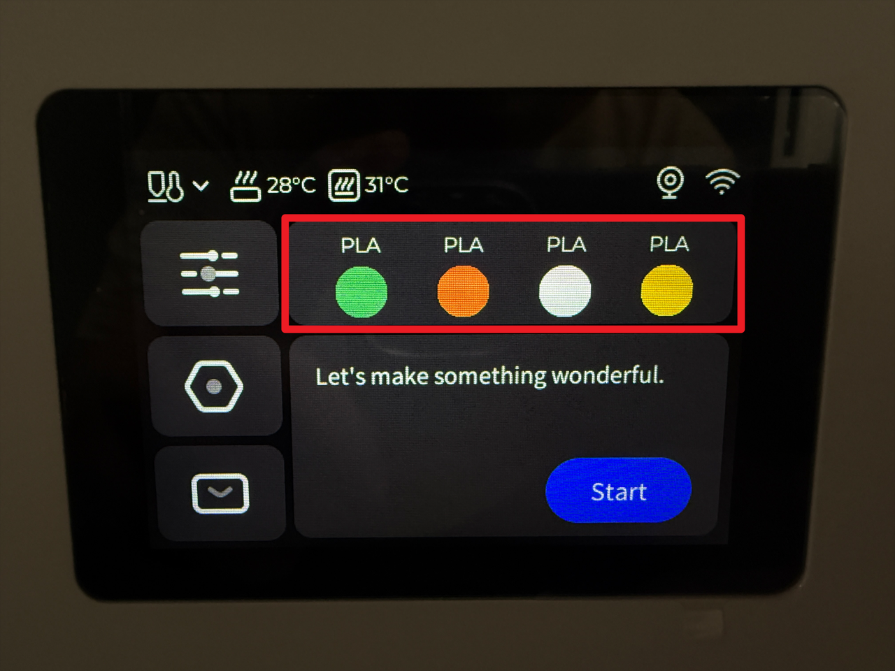
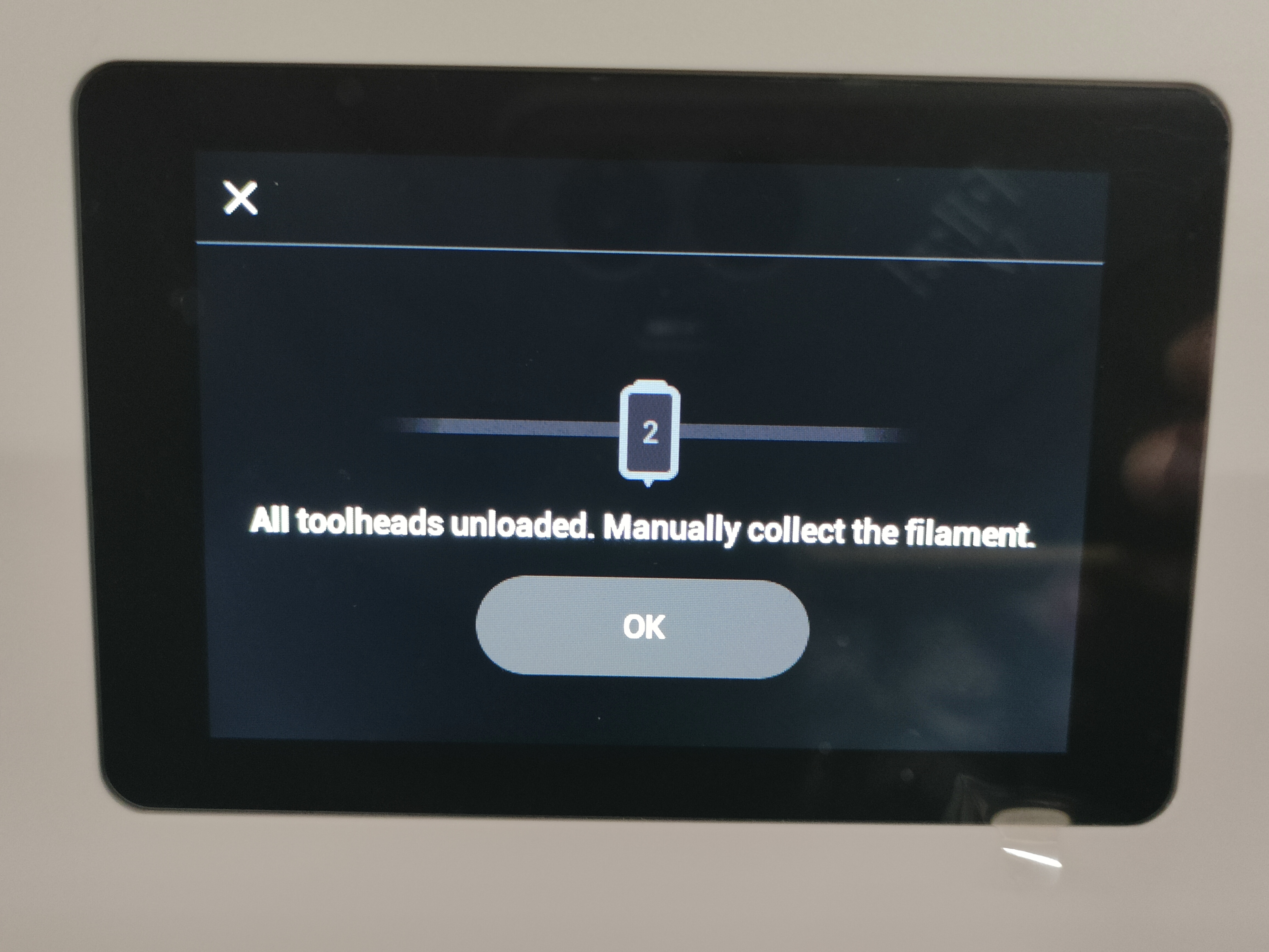
¶ 1.1 Unload filament
- Tap the specified area on the touchscreen (Highlighted in red in the image below).
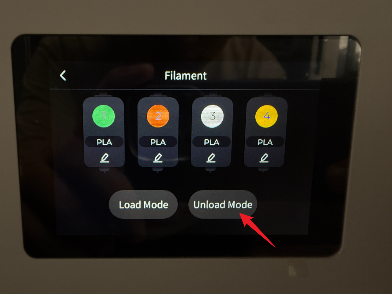
- Tap "Unload Mode".
- Select the target toolhead (e.g., No.2) and tap "Unload".
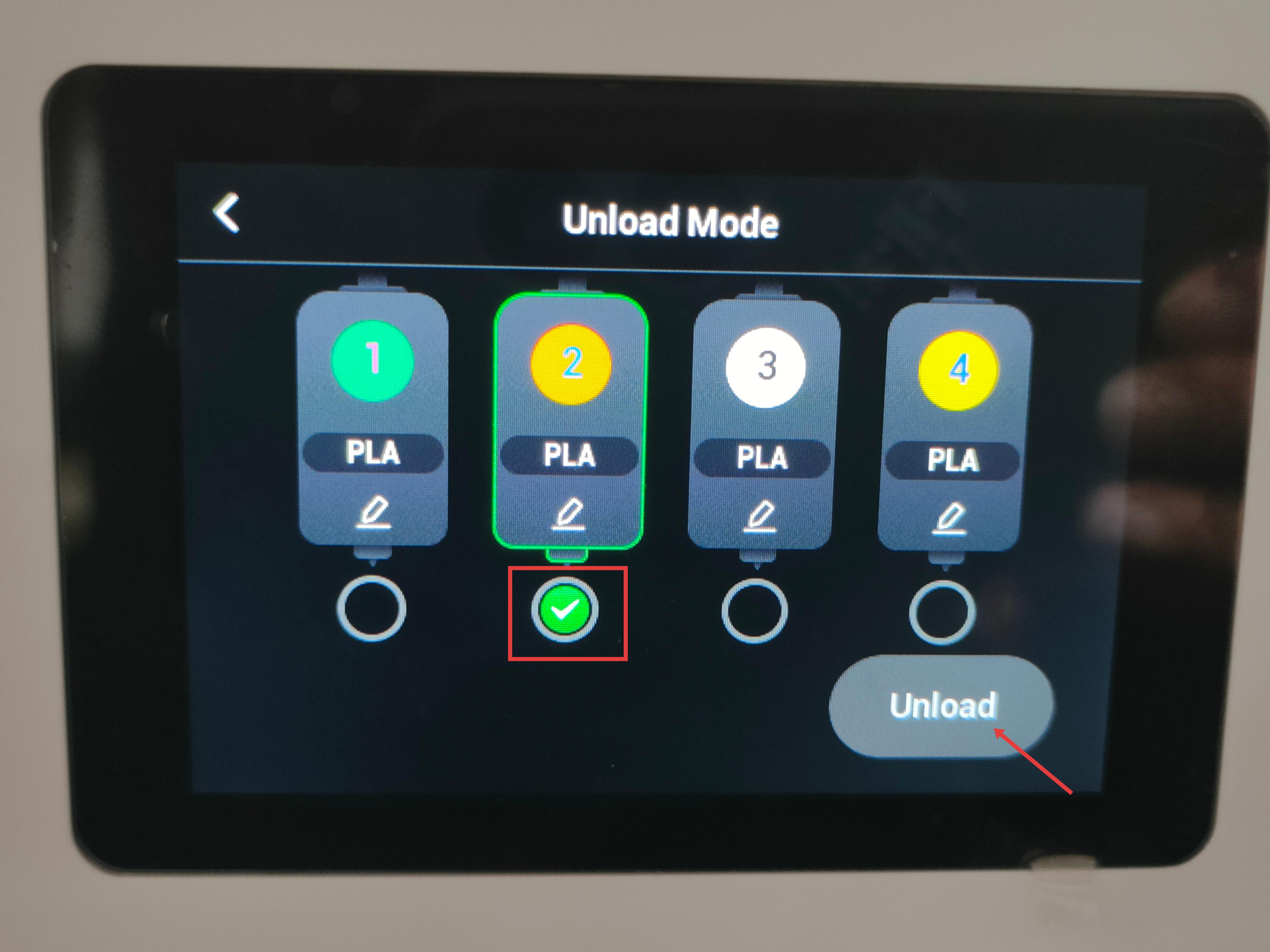
- Wait for the system to automatically complete the filament unloading.
¶ 1.2 Detach the toolhead from the docking bracket
Before proceeding, please turn off the machine and unplug the power cable!

- For head No.1: Slide to the right until the locating pin is fully visible.
- For heads No.2/3/4: Slide the toolhead to the left until the locating pin is fully visible.
¶ 1.3 Remove filament and guide tube
- Remove the three cable clips.
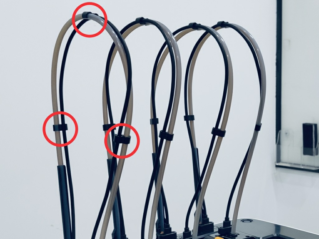
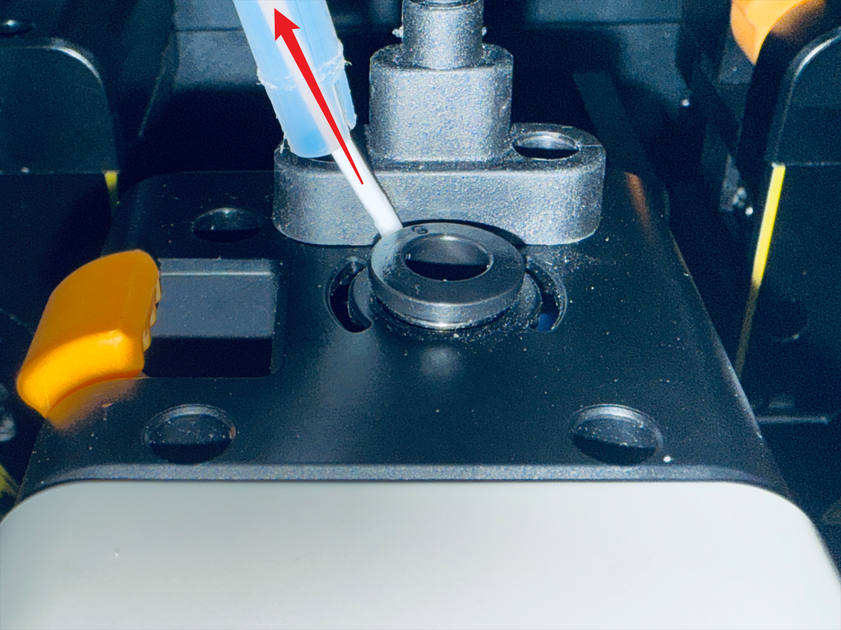
- Press the quick-release fitting.
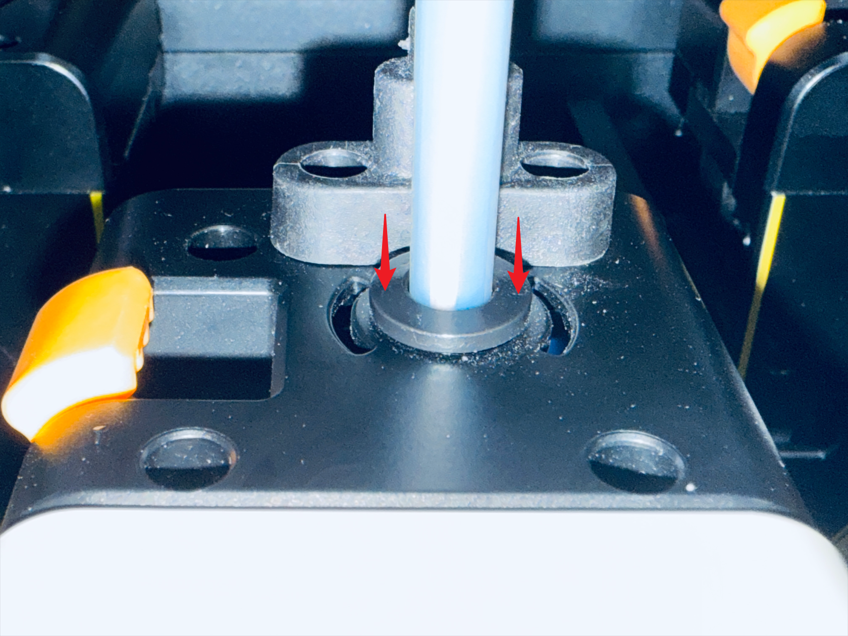
- Remove the filament and the filament tube.
¶ 1.4 Disconnect USB and remove the toolhead
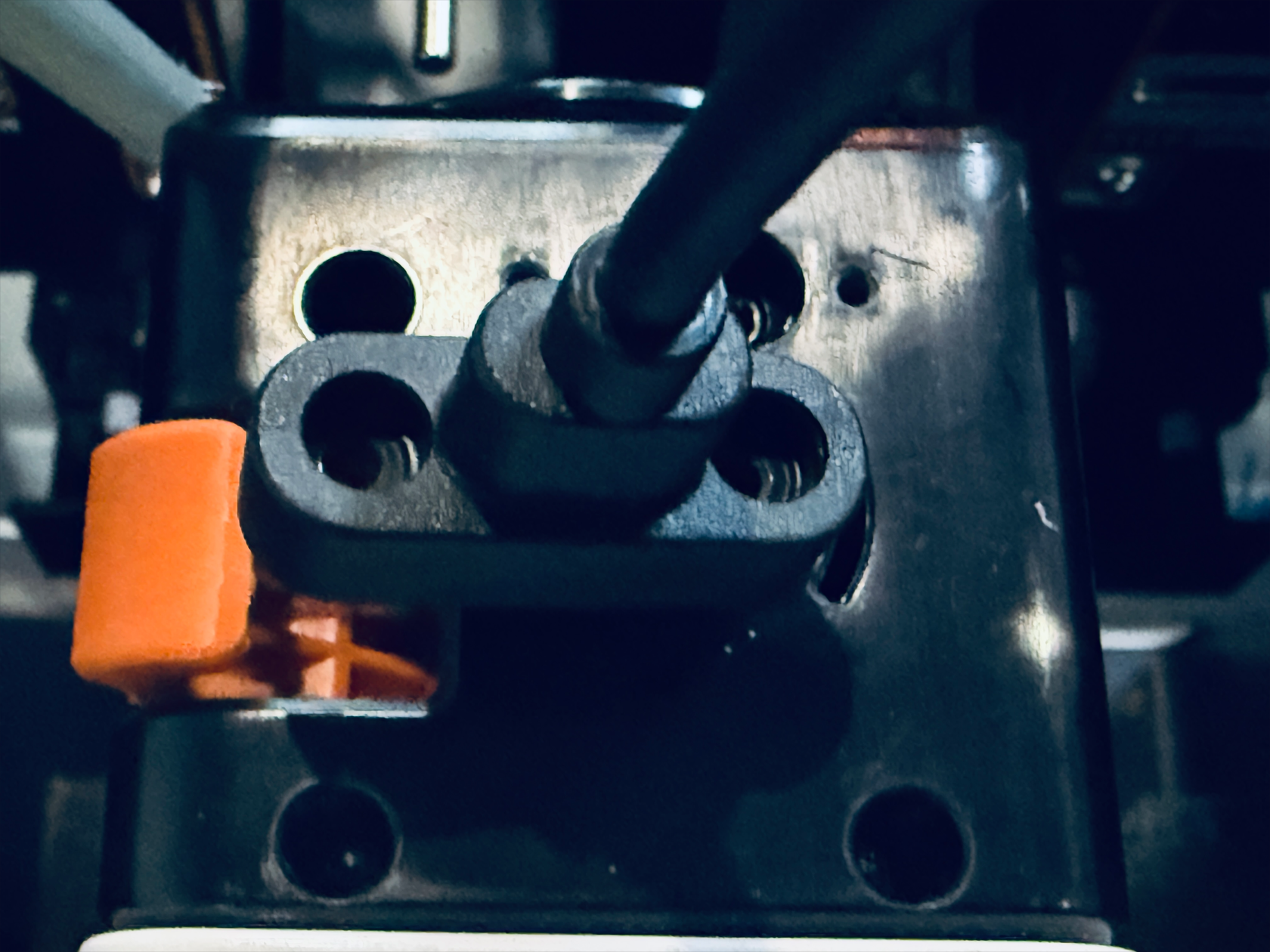
- Use the H2.0 hex key to remove the two mounting screws.
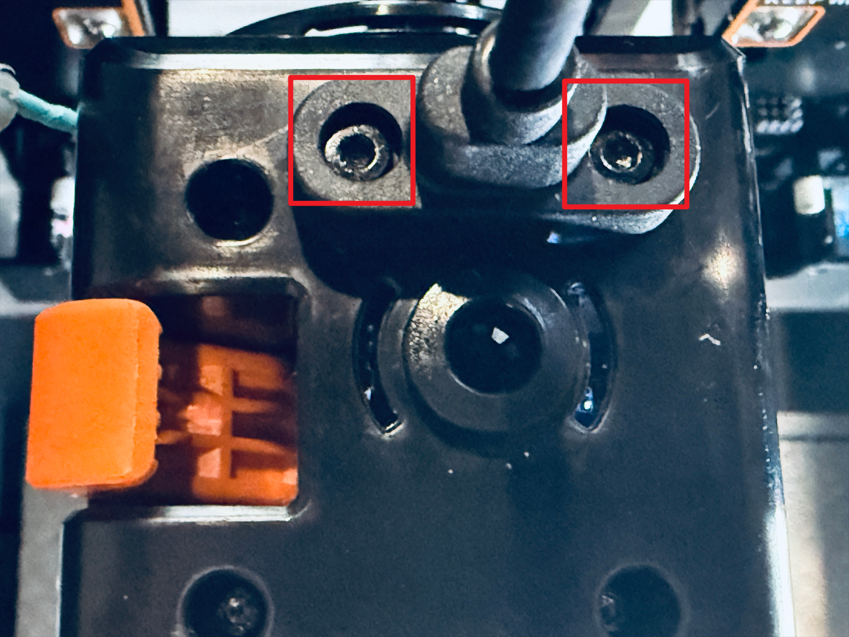
- Unplug the USB cable and then carefully remove the toolhead.
¶ Step 2. Remove the extruder unit
¶ 2.1 Remove top cover and back cover
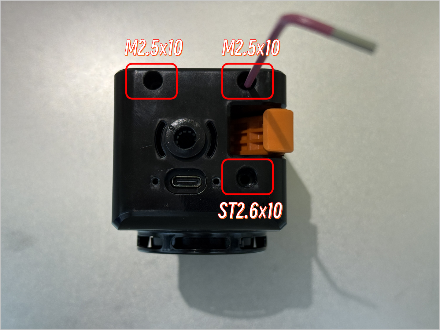
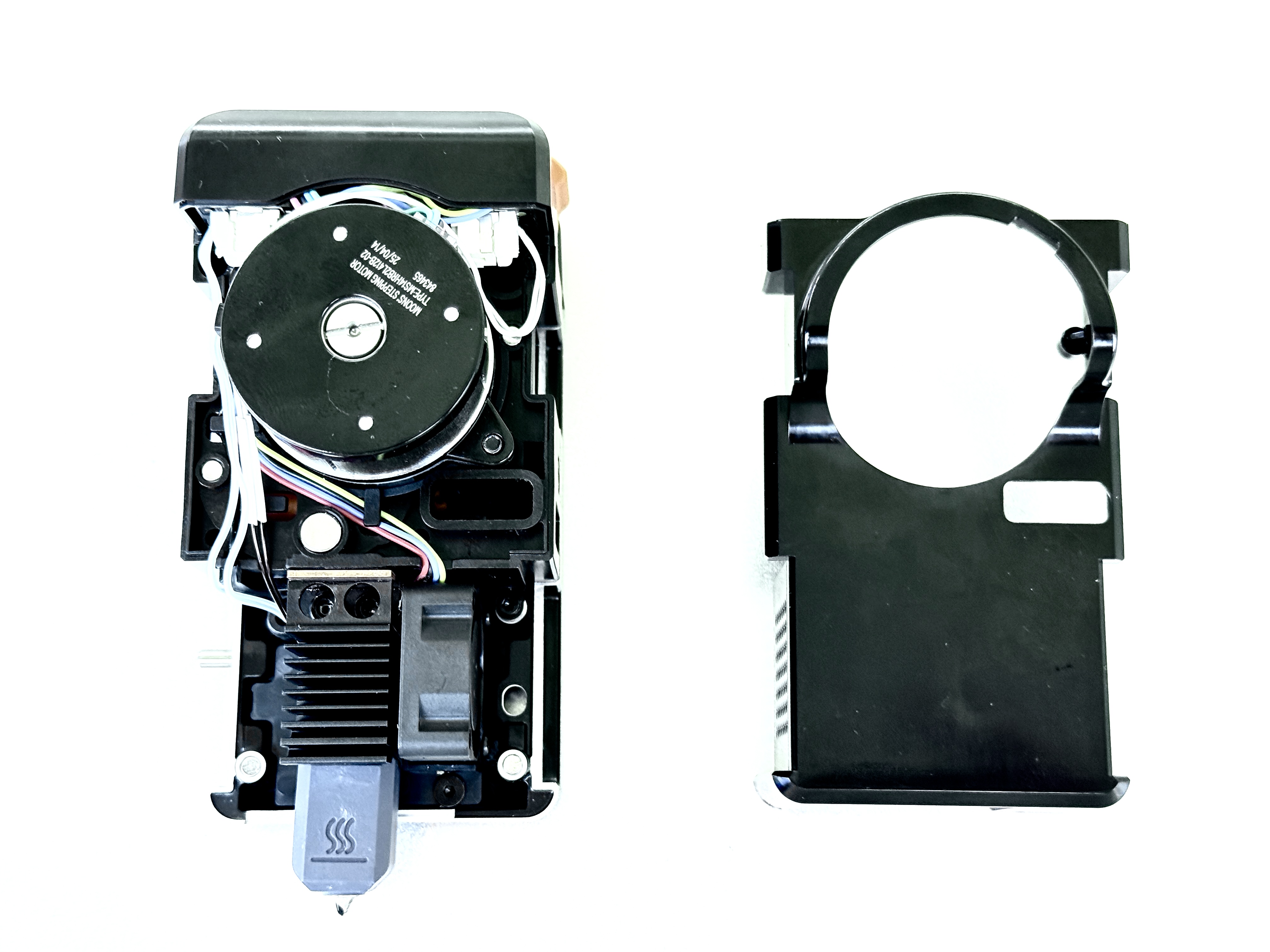
- Use the H2.0 hex key to remove the three screws securing the top cover of the toolhead, then remove the top cover.
- Remove the back cover of the toolhead.
¶ 2.2 Remove the extruder unit
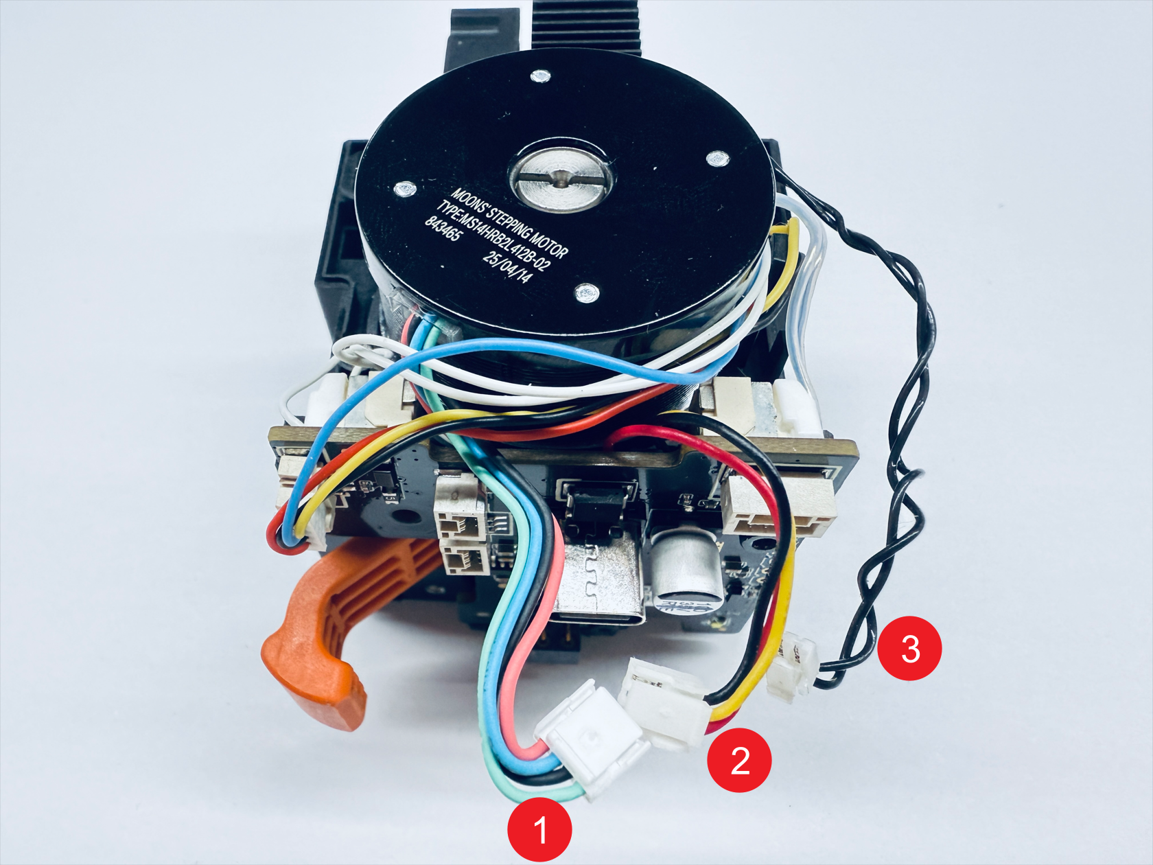
- Disconnect the extruder unit cables.
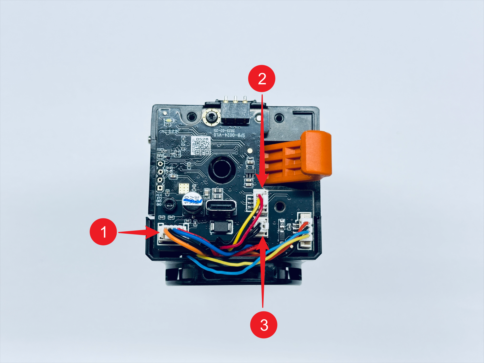
- Use the H1.5 and H2.0 hex keys to unscrew PCB fixing screw 1 and screw 2 respectively.
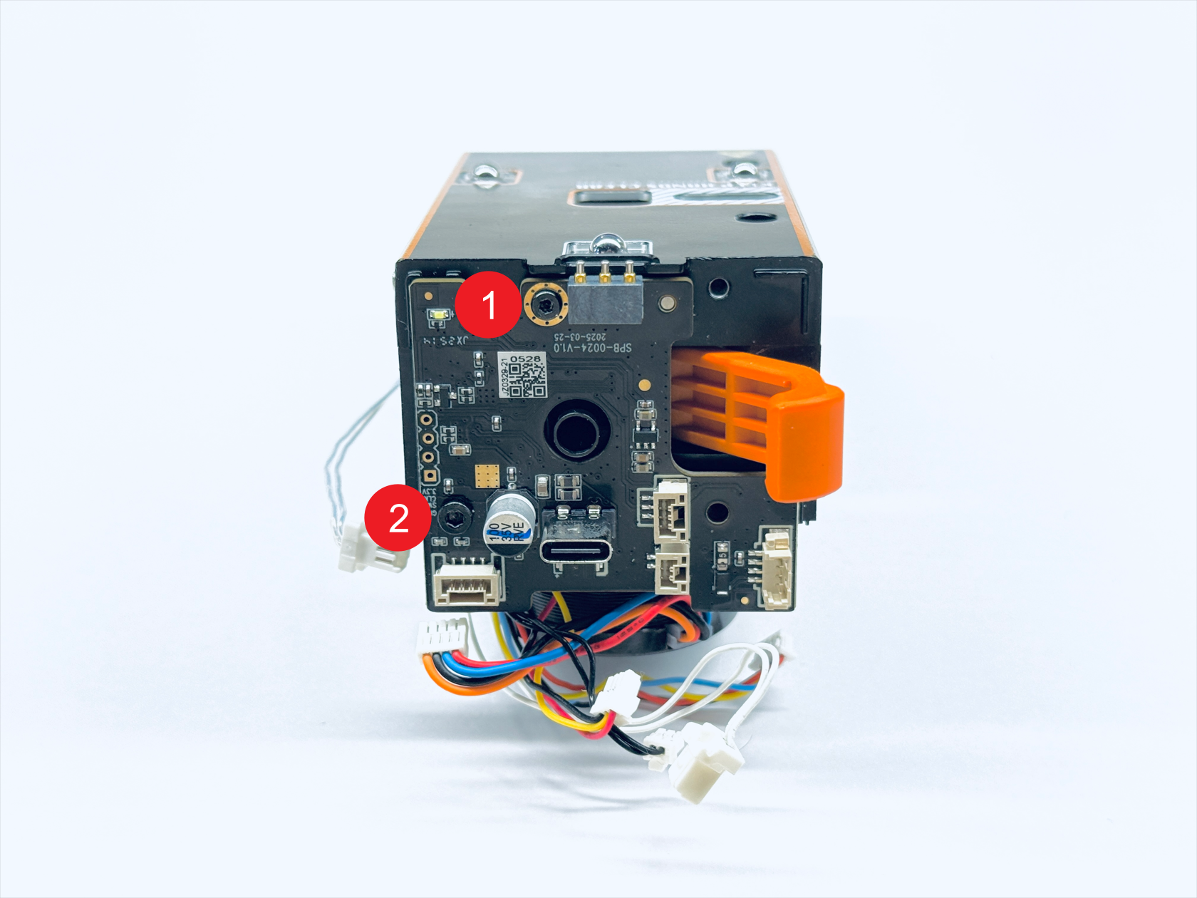
- Pull out the cables from the clips of the extruder unit.
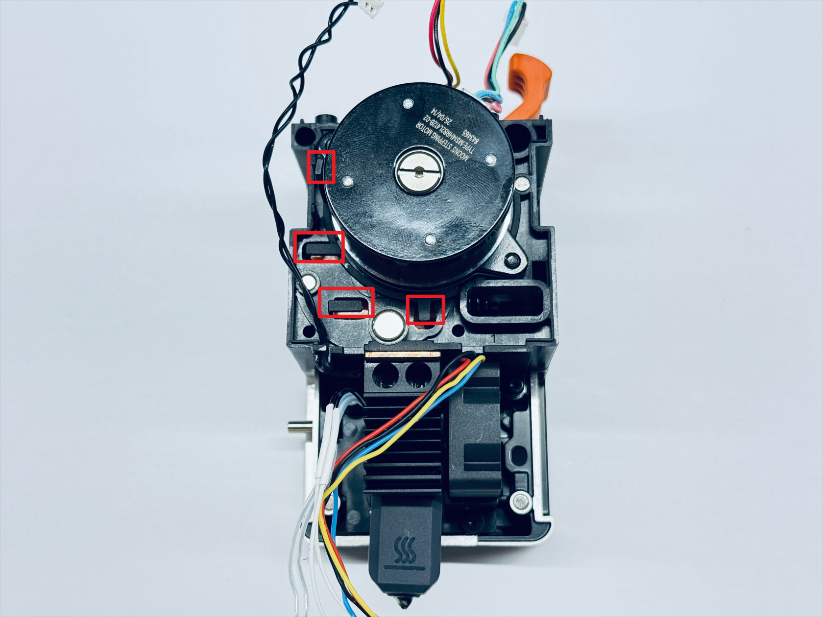
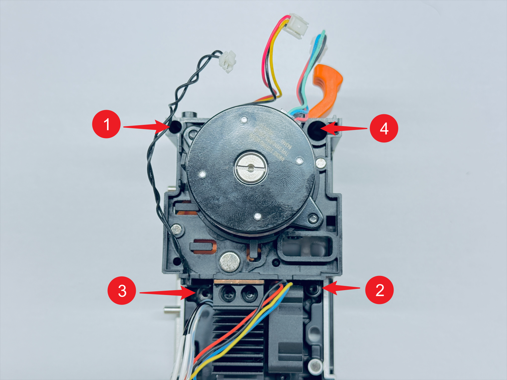
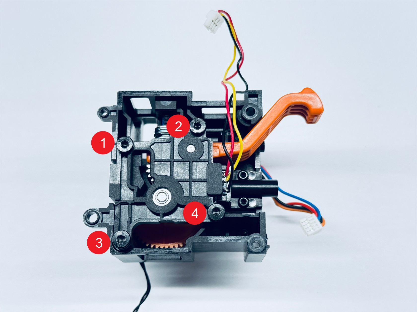
- Use the H1.5 hex key to unscrew fixing screw 1 and screw 2, and use the H2.0 hex key to unscrew fixing screw 3 and screw 4, then remove the extruder unit.
¶ Step 3. Remove the old active extruder gear assembly
- Use the H2.0 hex key to unscrew the 4 fixing screws, then remove the extruder bearing block.

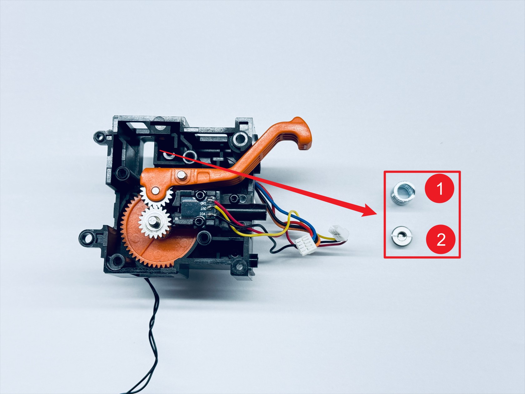
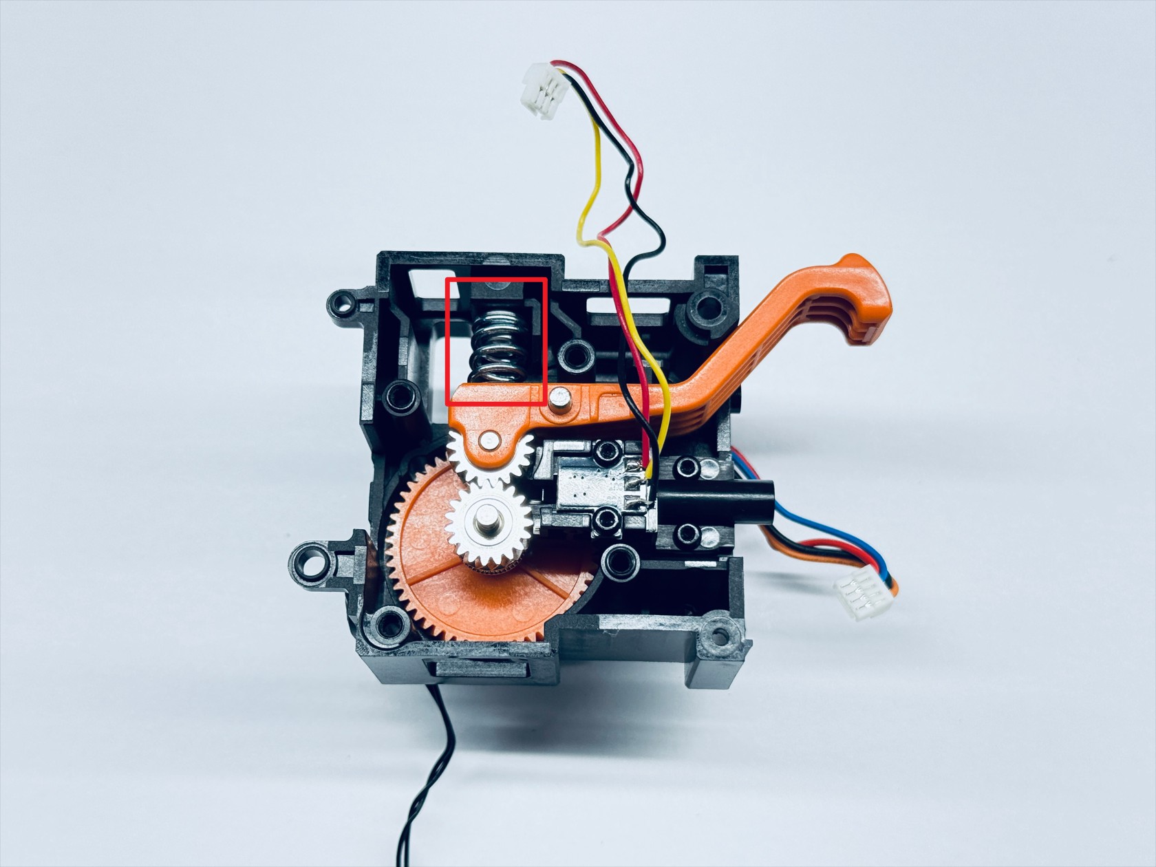
- Use the H2.0 hex key to unscrew the spring fixing screw and remove the compression spring—1 and the spring block—2.

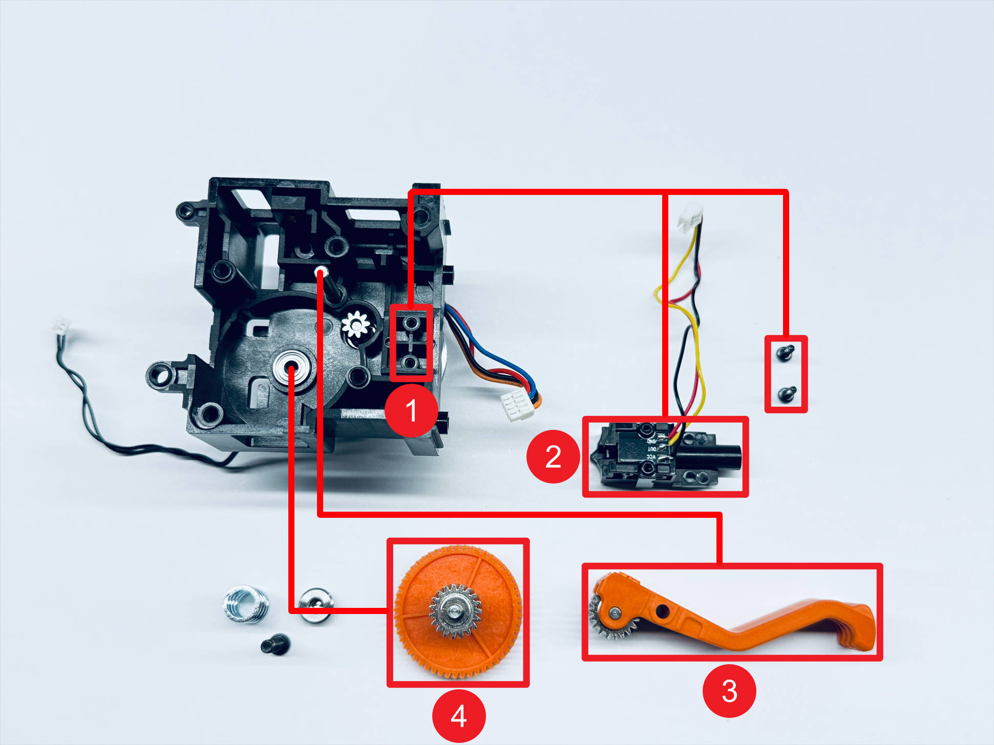
- Use the H1.5 hex key to unscrew the 2 fixing screws and sequentially remove the filament runout sensor—2, the driven extruder gear assembly—3, and the active extruder gear assembly—4.
¶ Step 4. Install the new active extruder gear assembly
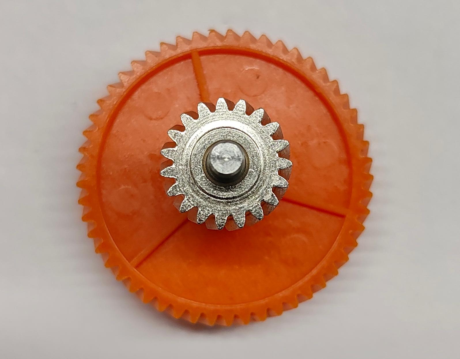
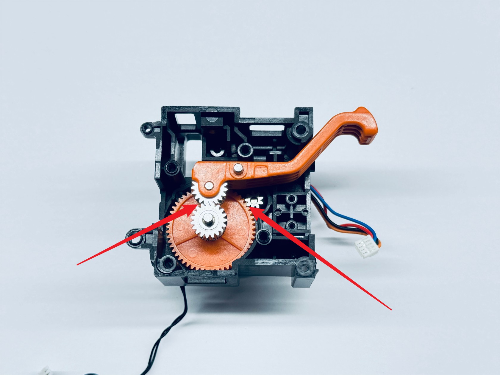
- Install the new active extruder gear assembly and the driven extruder gear assembly sequentially, ensuring that the 3 gears shown mesh correctly. Rotate the active extruder gear to confirm that the other two gears turn smoothly, indicating proper installation.
- Install the filament runout sensor and use the H1.5 hex key to tighten the 2 fixing screws.
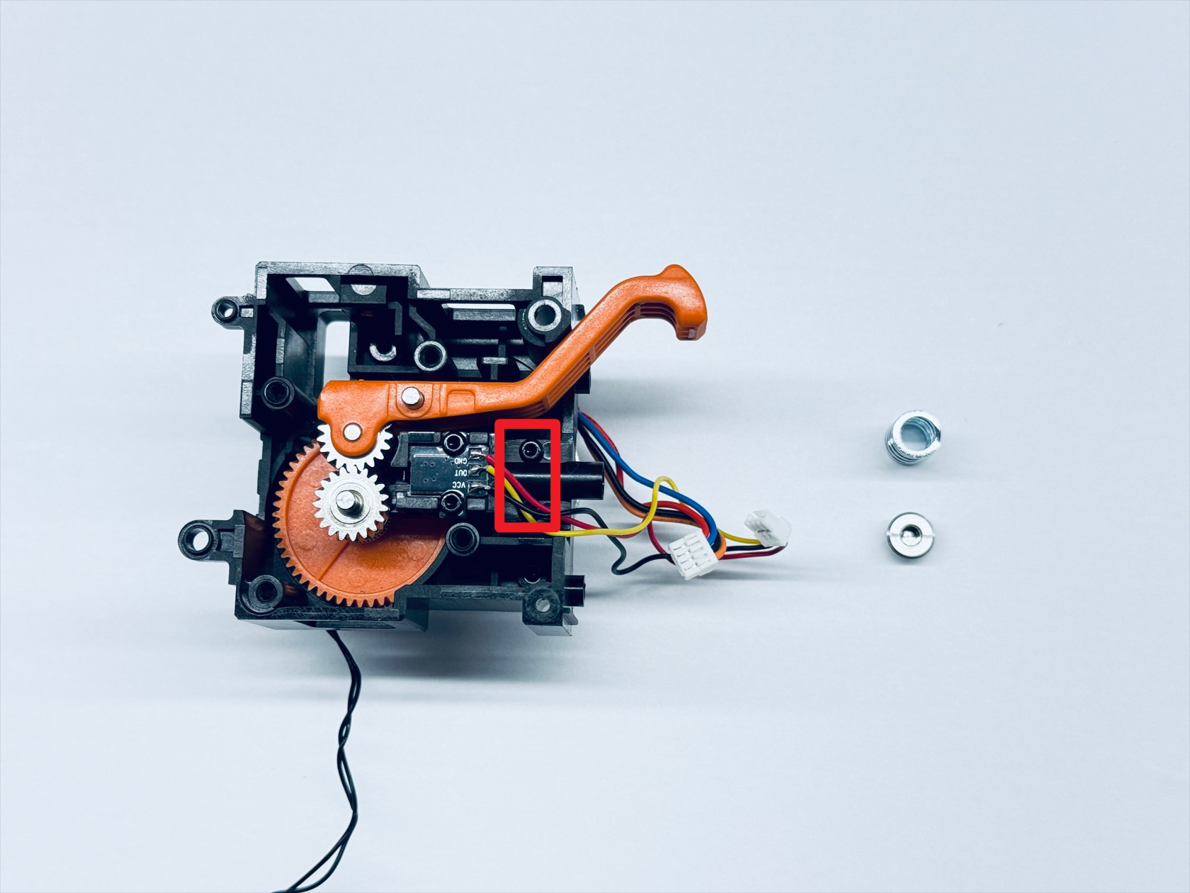
- Install the compression spring and spring block, placing the spring block above the compression spring, and use the H2.0 hex key to tighten the spring fixing screw.
- Reinstall the extruder bearing block and use the H2.0 hex key to tighten the 4 fixing screws.
¶ Step 5. Install the extruder unit
- Place the extruder unit in the position as shown, then use the H1.5 hex key to tighten fixing screw 1 and screw 2, and use the H2.0 hex key to tighten fixing screw 3 and screw 4.
- Reinstall the PCB. Note that the 3 cables of the extruder unit must be routed as shown in the picture.
- Use the H1.5 and H2.0 hex keys to tighten PCB fixing screw 1 and screw 2 respectively.
- Reconnect the extruder unit cables.
- Organize the cables as shown.
- Install the top cover of toolhead.
- Install the back cover of toolhead.
¶ Step 6. Install the toolhead
¶ 6.1 Place the toolhead onto the docking bracket
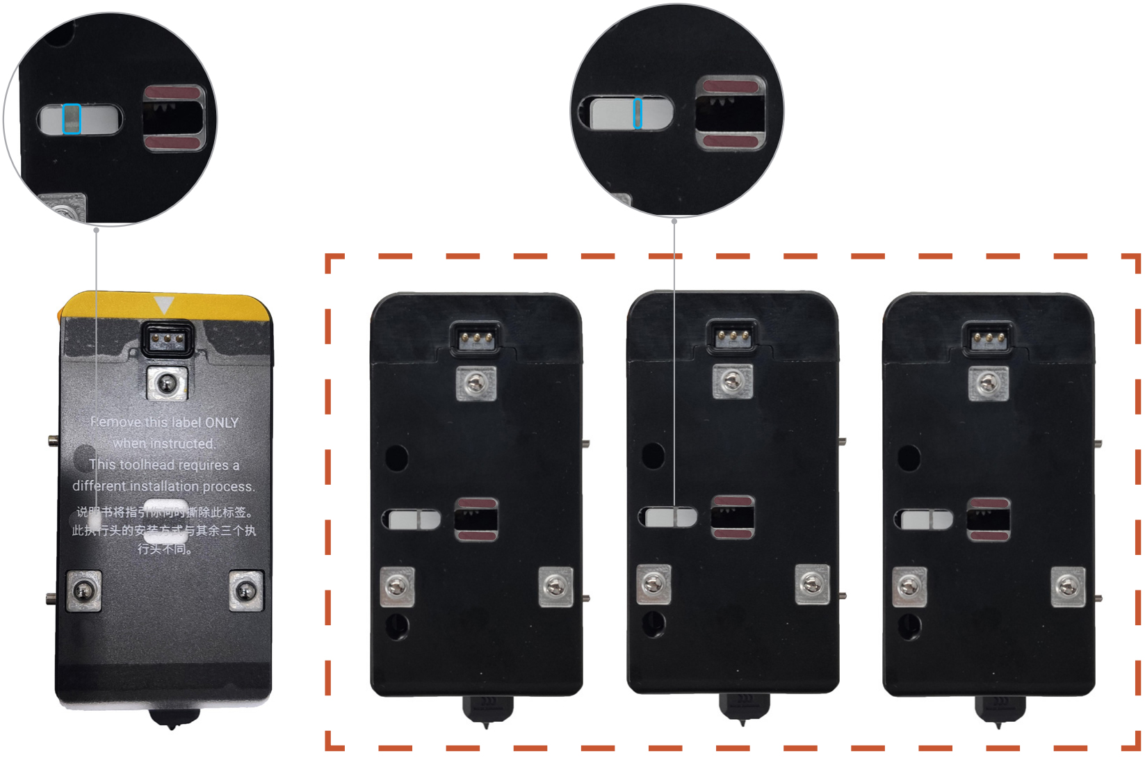
Before installing the toolhead, please make sure the sliders are in the correct positions. The slider for Toolhead No. 1 should be set to the far left, while the sliders for Toolheads No. 2, 3, and 4 should all be set to the far right.
You can use a hex key to adjust the slider and make sure the red mark on the slider is visible.
- Align the hole on the toolhead with the long locating pin on the docking bracket, and push inward until it stops.
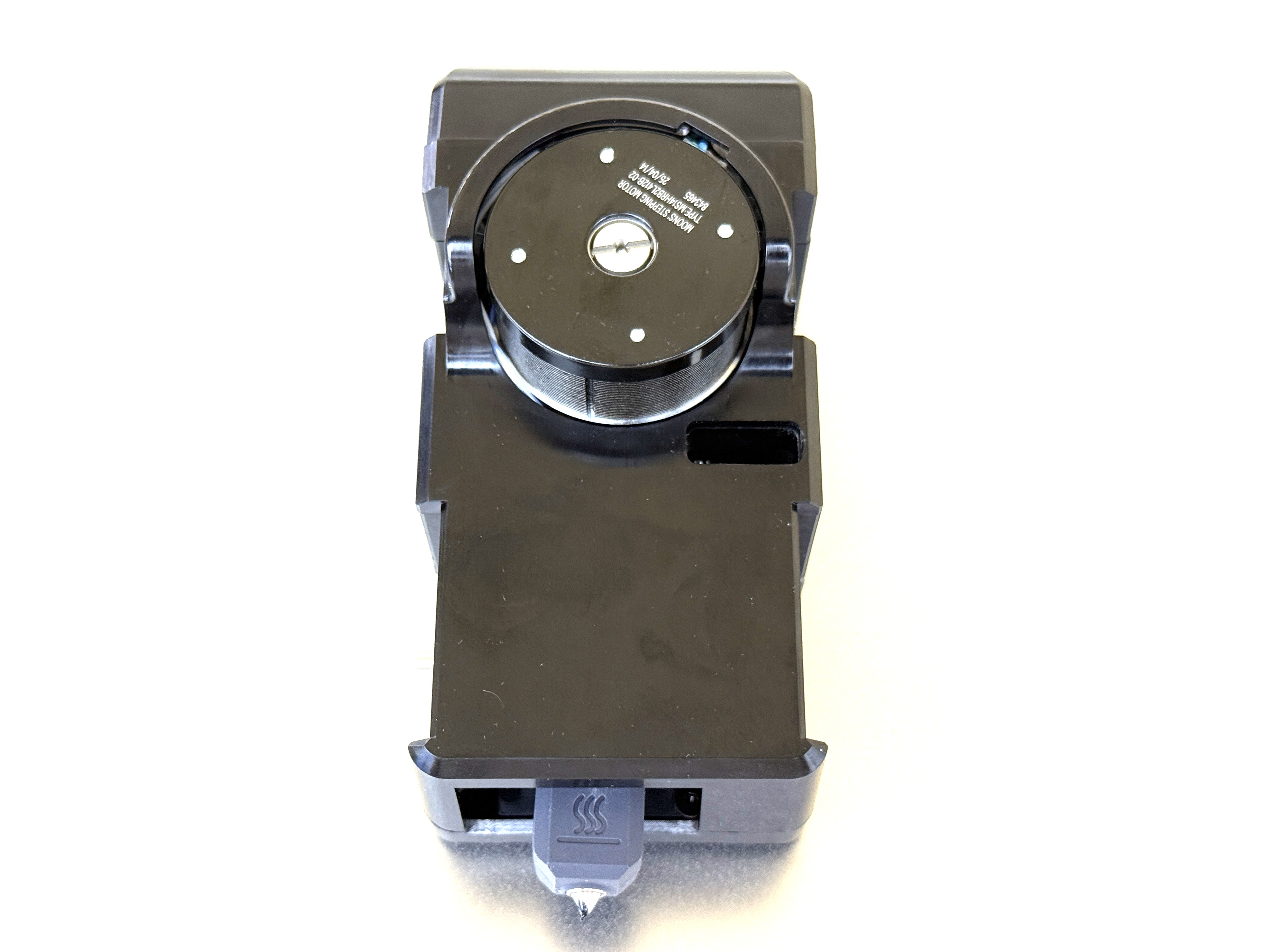
The illustrated side of the toolhead should face inward.
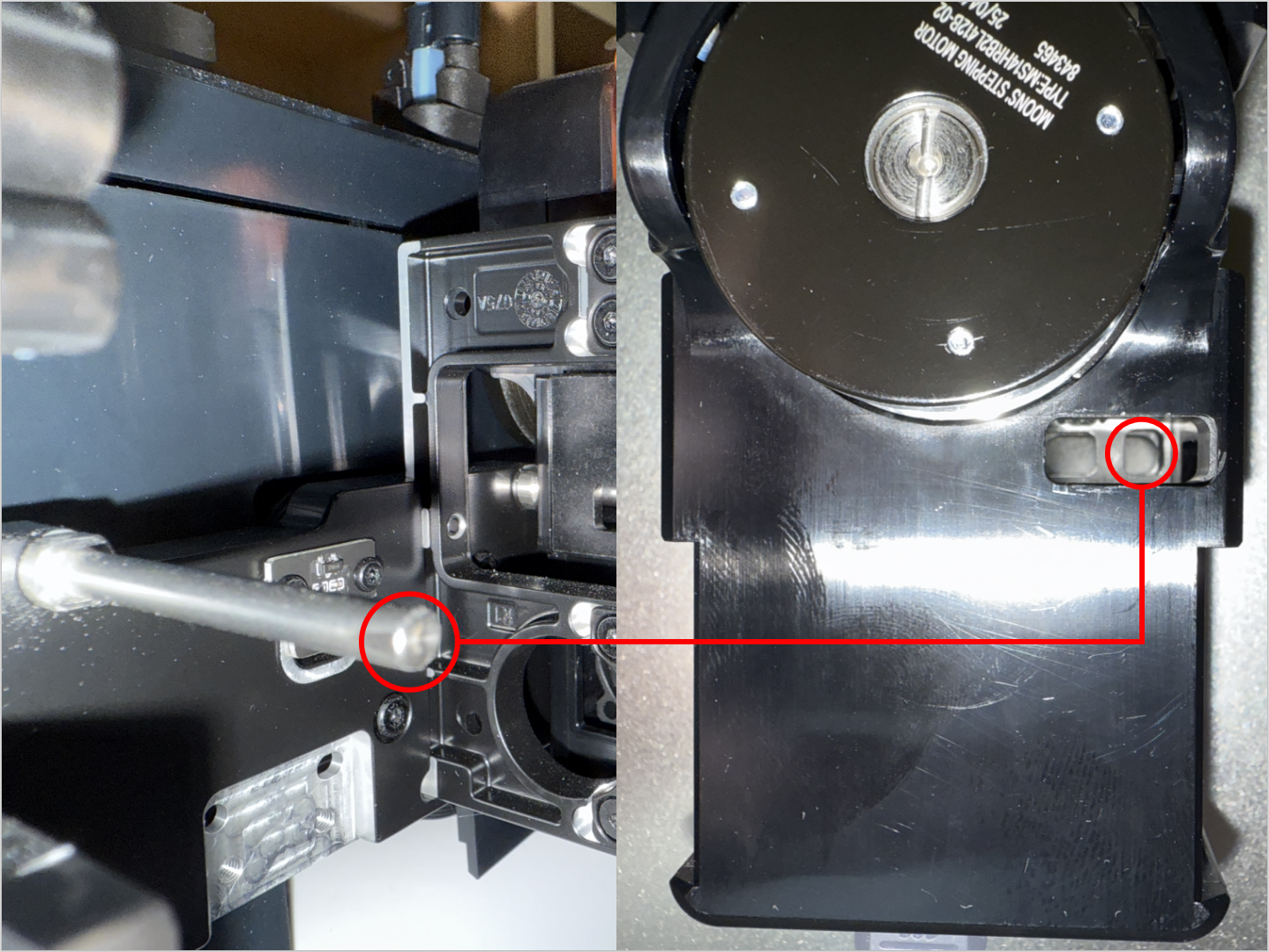
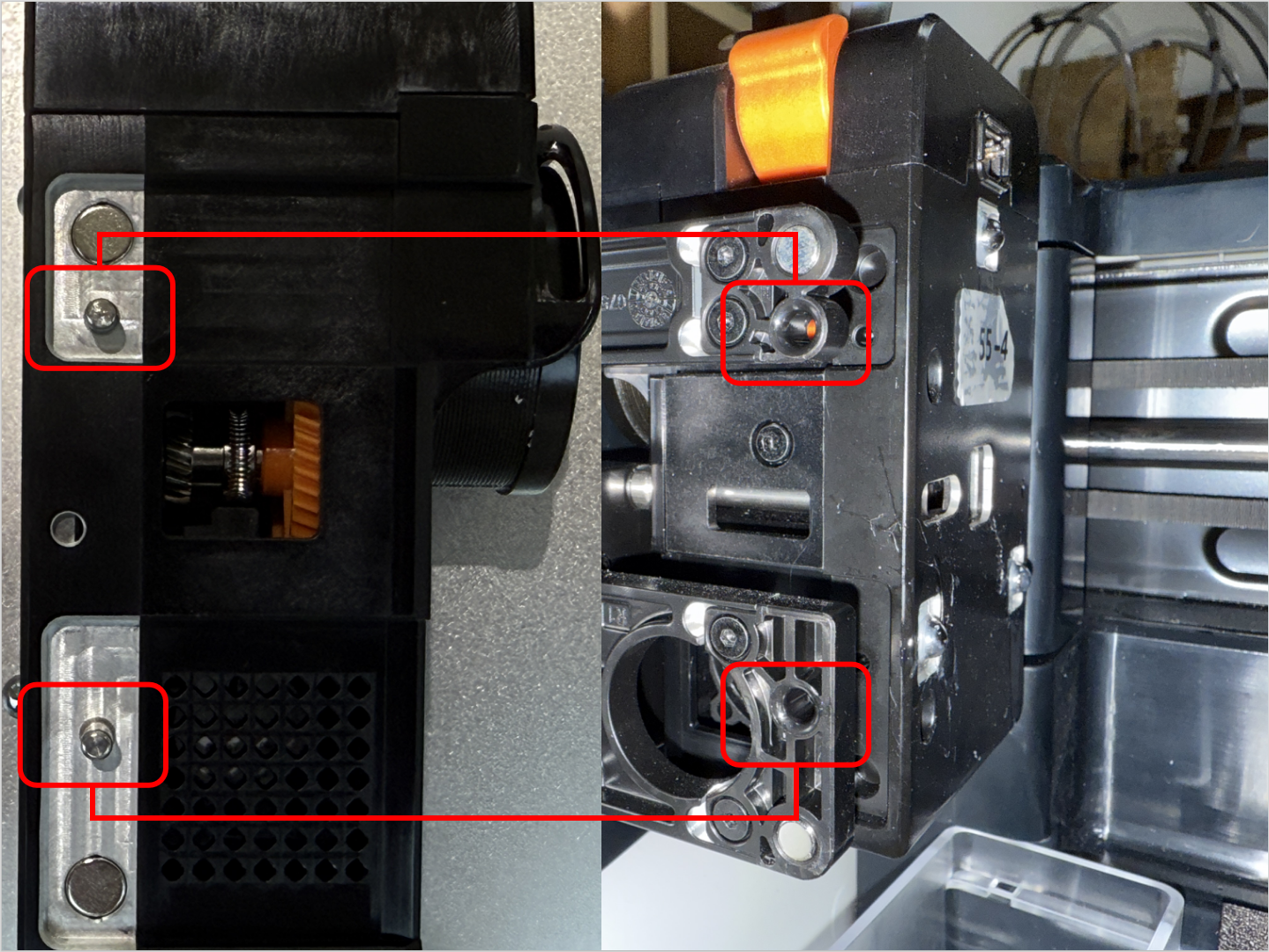
- Align the two locating pins on the toolhead with the holes shown on the mount.
For No.1 head: hole is to the left of the pins
For No.2/3/4 heads: hole is to the right of the pins
¶ 6.2 Connect and secure the USB cable
- Plug in the USB cable and fasten the two screws with the H2.0 hex key.
¶ 6.3 Load filament
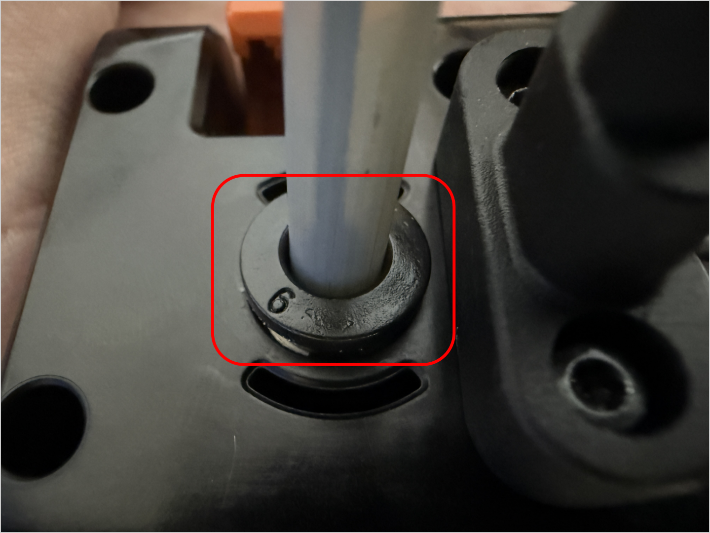
- While pressing part 1, as highlighted in the image below, insert the filament into part 2 until it reaches the end.
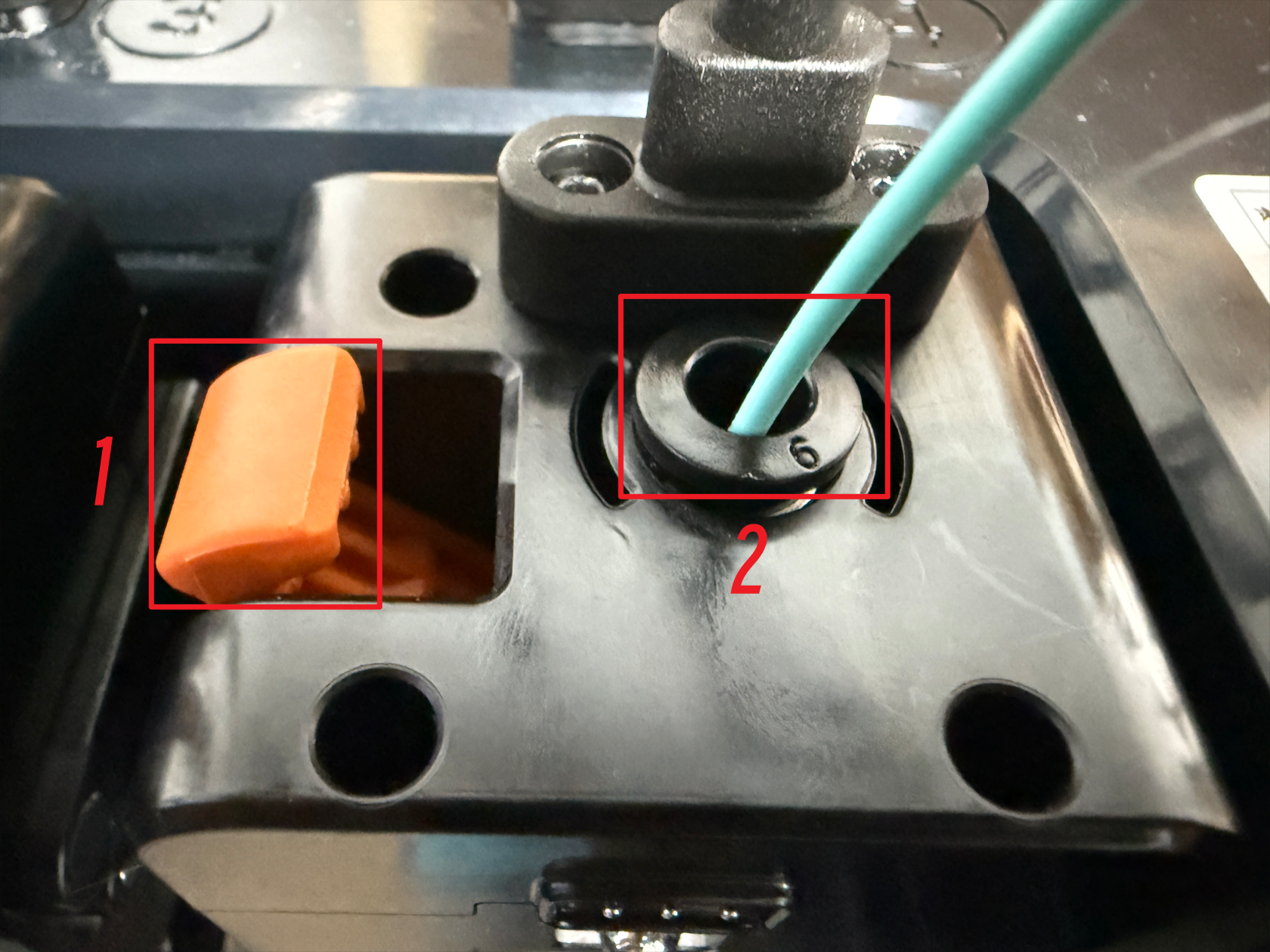
- Finally, connect the filament tube. The toolhead installation is now complete.
¶ Reach out to Snapmaker Support
After following the troubleshooting steps, if you find it difficult to resolve your issue, kindly submit a support ticket through https://snapmaker.formcrafts.com/u1-troubleshooting-request and share your troubleshooting results with some pictures/videos.
Our dedicated support team will be more than willing to assist you in resolving the issue.