¶ Compatibility
This article applies to the following models and modules. Please pay attention to the details when referring to it:
Model:J1
¶ Issue Description
-
The first-layer adhesion is inconsistent. On the right side, the nozzle is too far from the bed, and on the left side, the bed is too close, resulting in under-extrusion.
-
The back right corner of the print bed is higher, causing the nozzle to drag in that area, while printing is fine on the front and left side.
¶ Possible Causes
- Residue of filament on the nozzle or heated bed PCB may cause inaccurate calibration data.
- The heated bed clamps or their bases may be cracked or damaged.
- There could be play in the Z-axis guide rail bearings.
- The print platform or heated bed PCB may be uneven.
- The heated bed temperature is not set correctly.
¶ Troubleshooting Steps
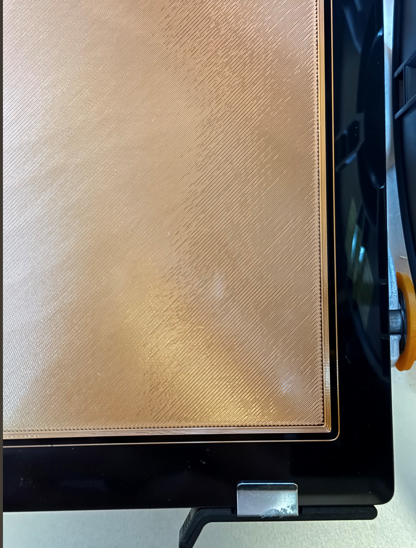
¶ 1. Before calibration, check the nozzle and heated bed for any remaining filament.
If there is any, use the appropriate tools to clean the nozzle or heated bed PCB. Be careful not to damage the heated bed.
¶ 2. Check all platform clips and the base of the platform clips on the heated bed for cracks or damage.
If the clips or their bases are damaged, it can cause the heated bed to become loose, which will lead to inaccurate calibration data.
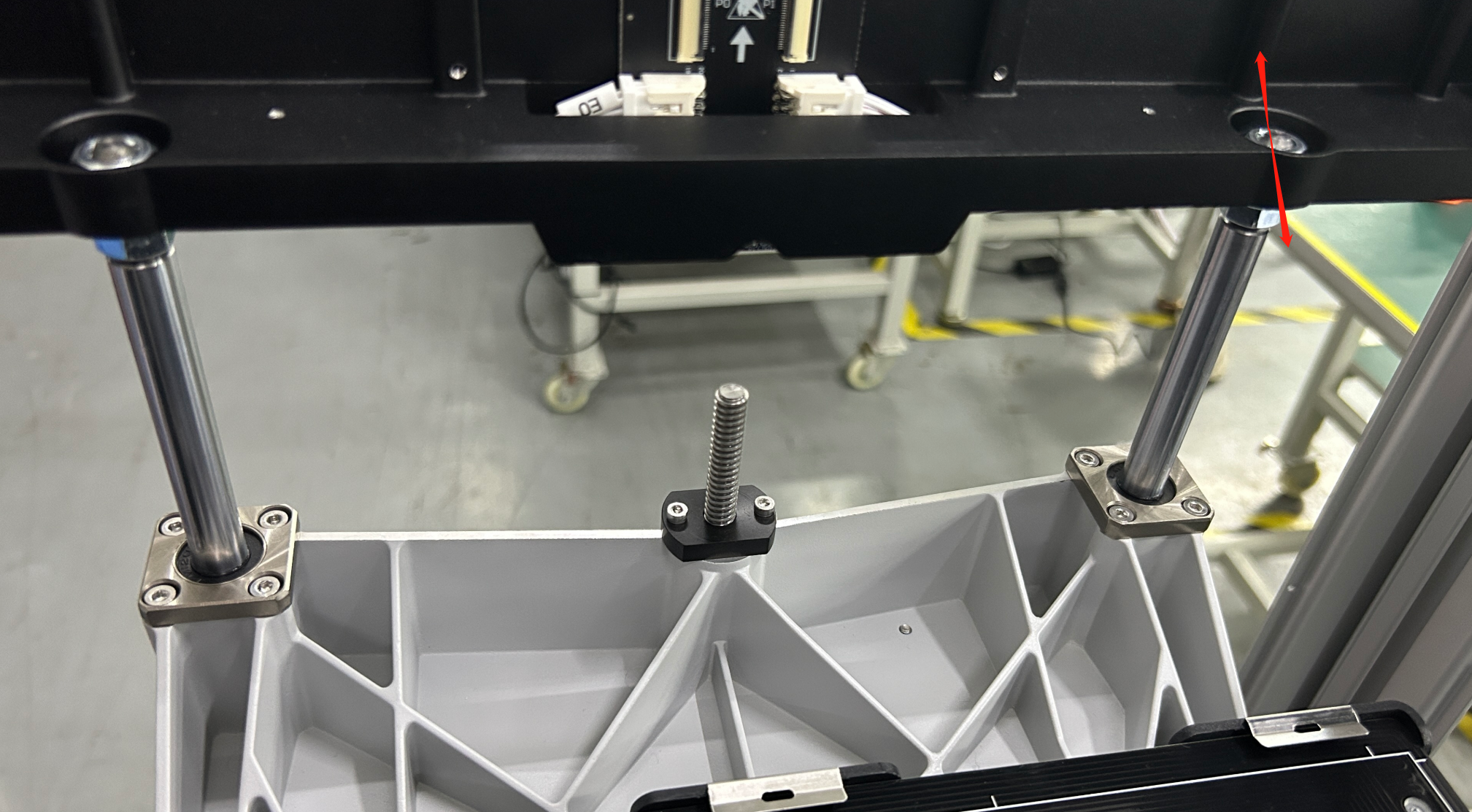
¶ 3. Check if there is any play in the Z-axis guide rail bearings.
Raise the Z-axis to the highest point, then gently move the heated bed bracket up and down to check if there is any looseness at the Z-axis guide rail bearings or if you hear any clicking sounds. Please refer to the video below for guidance.
Here is a video showing how to check for looseness in the Z-axis guide rail bearings
If you notice that the Z-axis guide rail bearings are loose as shown in the video, please follow the steps below to adjust and fix the issue:
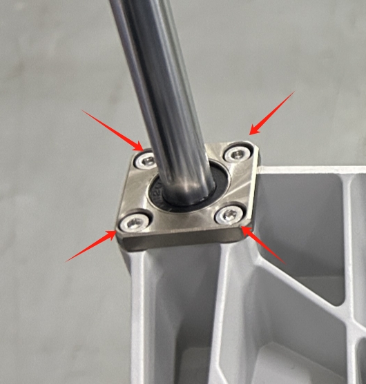
- Use a socket wrench to loosen the screw on the guide rail where the wobble occurs. After loosening, adjust the guide rail forward or backward along the Y-axis and check if the wobble improves.
- If the wobble improves, loosen the four screws on the linear bearing flange to let it self-adjust, then tighten them again.
¶ 4. Check if the printing platform and the heated bed PCB are flat:
4.1 Check the printing platform
Rotate the glass plate 180 degrees horizontally and then re-calibrate and print. Check if the issue moves to another corner. For example, if the right top corner was previously too far from the heated bed, does it now become the left bottom corner after rotating the glass plate 180°?
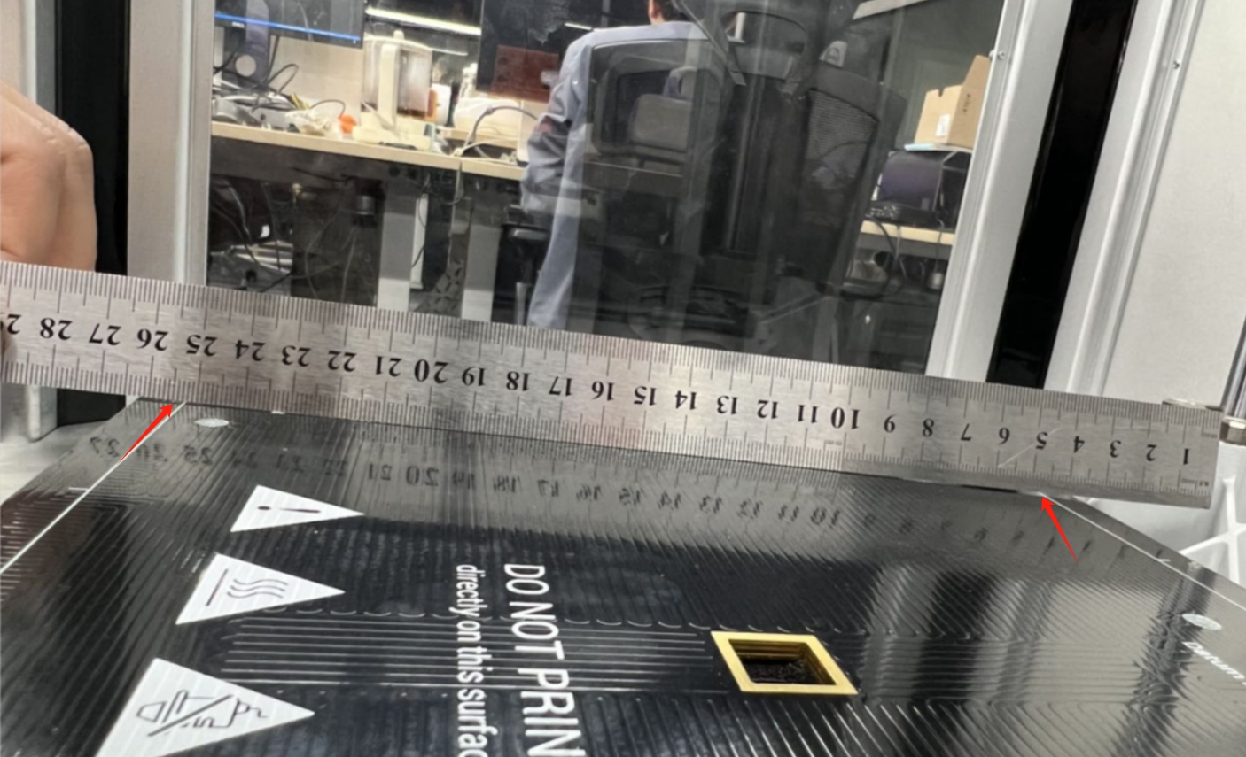
If the issue moves, you can use a long ruler (one that spans the entire printing platform). Place the printing platform on a flat surface and lay the ruler across it. Check for any visible gaps to determine if the printing platform is uneven.
4.2 Check the heated bed PCB
Place the long ruler on the PCB. Observe for any visible gaps to check if the PCB is uneven.
Heat the bed to 70°C, then wait for 15 minutes before measuring again to see if the heated bed PCB is uneven.
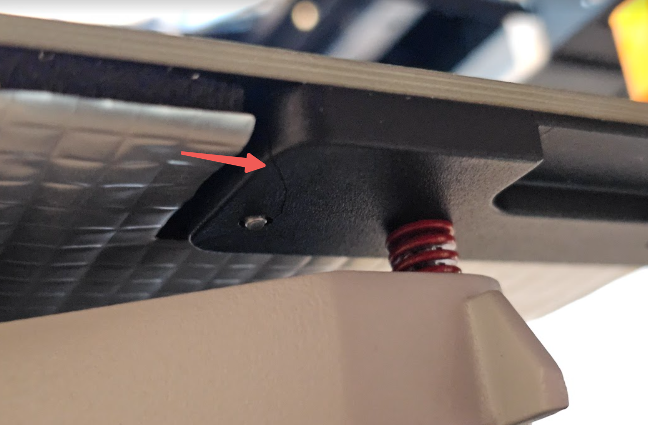
¶ 5. Adjust the hand-twist knob under the heated bed
After calibration is completed, placing the printing platform onto the heated bed PCB may cause slight changes in the height at each corner, so fine-tuning is necessary:
- Please download and print the gcode from the link below:
-
After printing, use a caliper to measure the thickness of the model at all four corners, and use a marker to write the measured thickness on the corresponding printed squares.
-
If the thickness at any of the four corners is not 0.2 mm, you will need to manually adjust the corresponding black hand-twist knob under the heated bed:
A. There are 10 notches on the black hand-twist knob, and each notch represents a 0.05 mm height adjustment.
B. Based on the measured values, rotate the black hand-twist knobs accordingly to fine-tune the bed height.
¶ Reach out to Snapmaker Support
After following the troubleshooting steps, if you find it difficult to resolve your issue, kindly submit a support ticket through https://snapmaker.formcrafts.com/support-ticket and share your troubleshooting results with some pictures/videos.
Our dedicated support team will be more than willing to assist you in resolving the issue.