¶ When to Calibrate
Refer to the table below to learn about when to do what calibration to ensure your 3D printer works properly.

¶ Thickness Measurement Calibration
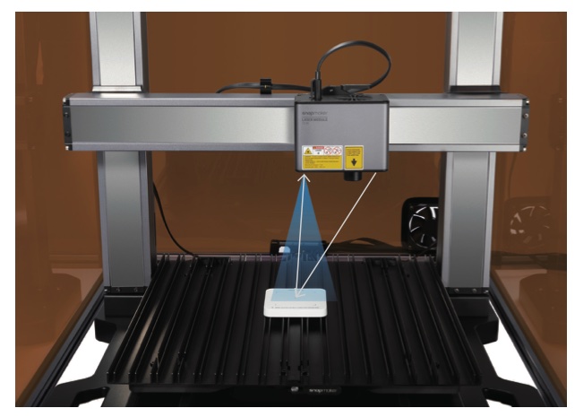
The 10W Laser Module features a thickness measurement system that uses the triangulation technique. The system includes a red laser emitter that projects a red dot on the material surface and a camera that captures the red dot image to calculate the material thickness.
The Thickness Measurement Calibration adjusts the parameters in the thickness measurement system to ensure accuracy. In this process, a laser calibration plate with known thickness is first used to help the machine determine the height of the laser engraving and cutting platform and then as a measured object to calibrate the system parameters.
Before you use the thickness measurement system for the first time, you need to calibrate its initial parameters.

The red laser emitter is a Class 2 laser product. Do NOT look directly into its aperture when the laser beam is being emitted.
To calibrate the thickness measurement system:
- On the Touchscreen, tap Calibration > Thickness Measurement Calibration.
- Follow the on-screen instructions to calibrate.
¶ Platform Height Calibration
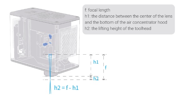
The focal length is the distance from the center of the lens to the focal point of the lens. For the 10W Laser Module, the focal length (f) is a fixed value. Besides, the distance (h1) from the center of the lens to the bottom of the air concentrator hood is also known to the machine. Based on these two values, the machine can calculate the lifting height (h2) of the toolhead after the toolhead touches the calibration plate during the platfrom height calibration.

To calibrate the platform:
- On the Touchscreen, tap Calibration > Platform Height Calibration.
- Follow the on-screen instructions to calibrate.
¶ Camera Calibration
The 10W Laser Module contains a wide-angle HD camera to capture the image of the work area, generating a background to edit the laser engraving and cutting objects. By using Camera Capture, you can position the laser engraving and cutting area.
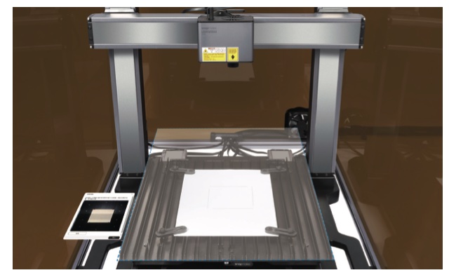
Camera Calibration adjusts the scale of the captured image to display a proper view of the work platform after Camera Capture. During this process, the machine will engrave a square on a piece of blank paper and capture its image to calibrate the camera.
To calibrate the camera:
- On the Touchscreen, tap Calibration > Camera Calibration.
- Follow the on-screen instructions to calibrate.
