¶ Before You Start
Detach the Dual Extrusion Module from the machine first.
¶ Tools & Accessories Required
- Filament runout sensor components pack × 1
- H2.0 screwdriver × 1
- H1.5 screwdriver × 1
- Tweezers × 1
¶ Procedures
¶ Video Tutorial
Please watch this video for visual instructions.
¶ Text Version of the Video
¶ Step 1. Detach the old filament runout sensor.
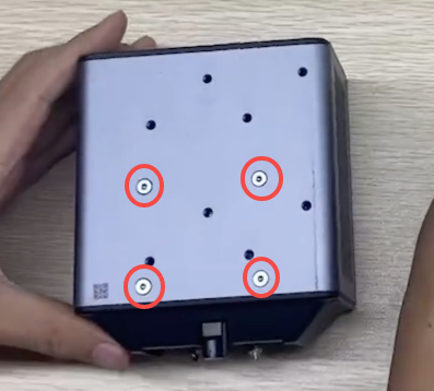
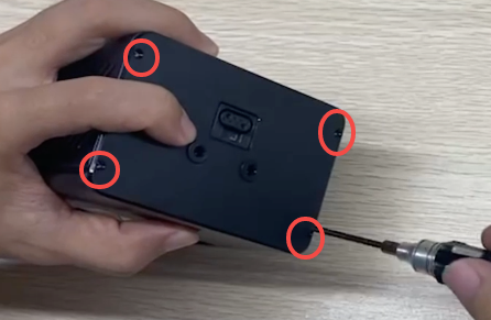
- Use the H2.0 screwdriver to remove the four screws on the back of the module.
If a quick-swap plate is installed, you need to detach it first.
-
Detach the hot ends.
-
Use the H1.5 screwdriver to remove the four screws on the top of the module.
-
Detach the front cover and shell.
-
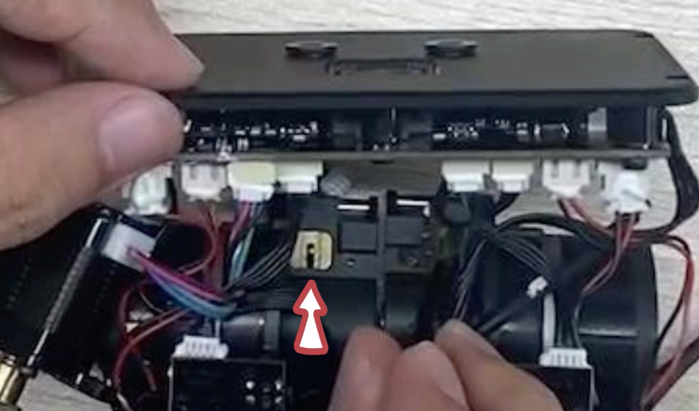
Disconnect the two motor cords.
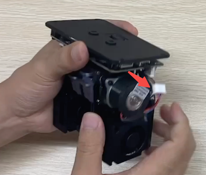
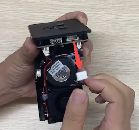
-
Use the H2.0 screwdriver to remove the two motor securing screws, then take out the motor.
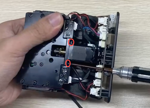
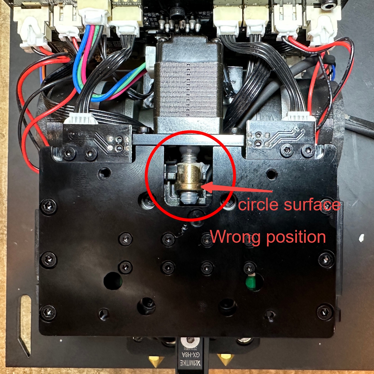
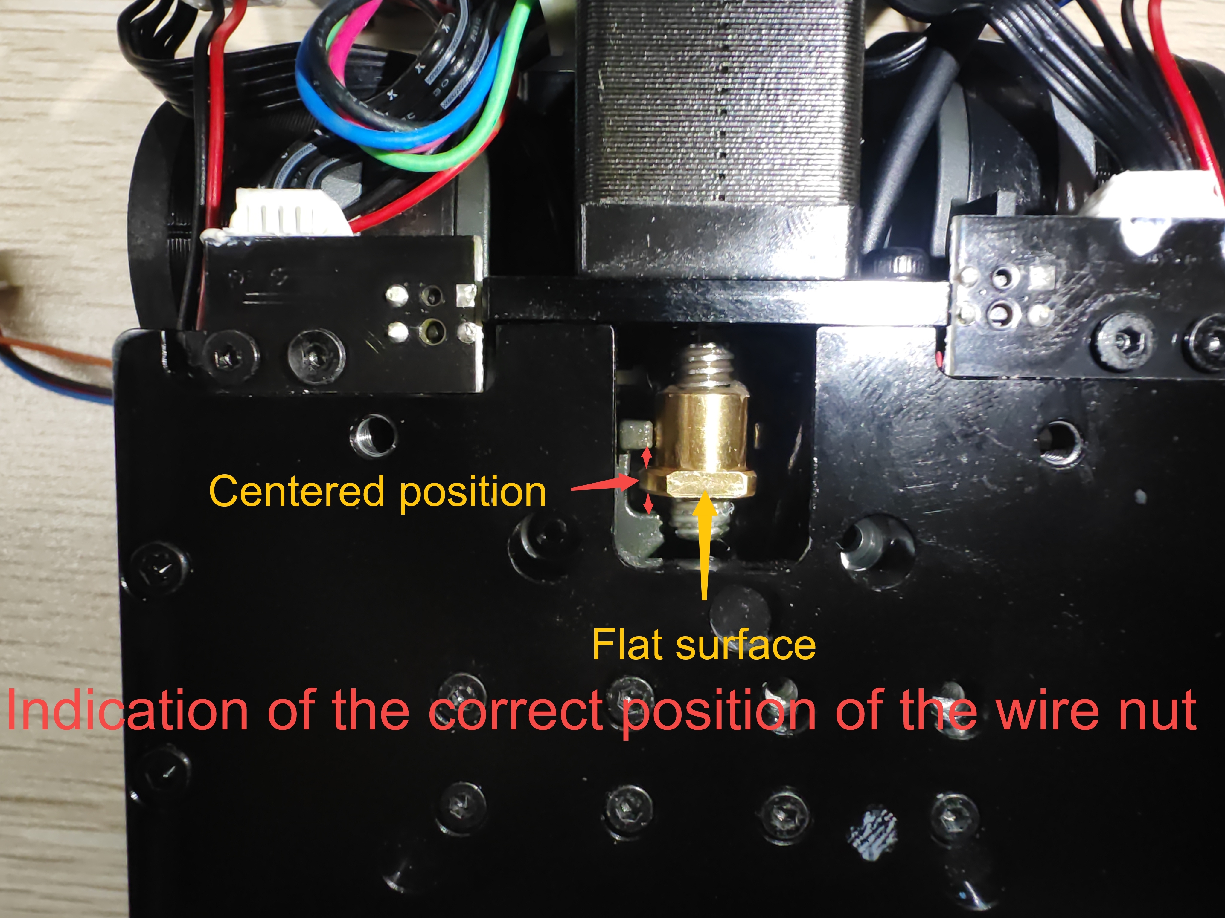
Be careful not to change the position of the lead screw nut of the motor during the operation.
-
Use the H1.5 screwdriver to remove the two sensor securing screws, then take out the sensor.
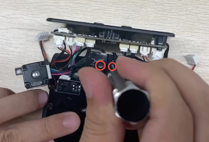
-
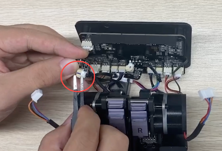
Use tweezers to remove the adhesives around the connectors, and then disconnect the cords. The old filament runout sensor is now detached.
¶ Step 2. Install the new filament runout sensor.
-
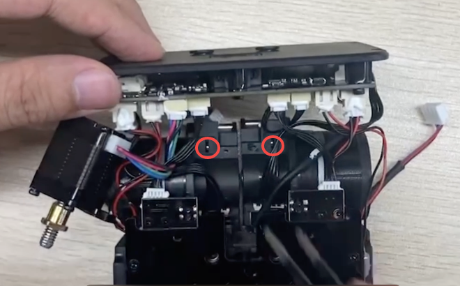
Install the trigger pads.
-
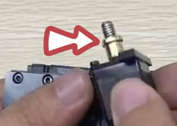
Install the copper blocks to secure the trigger pads.
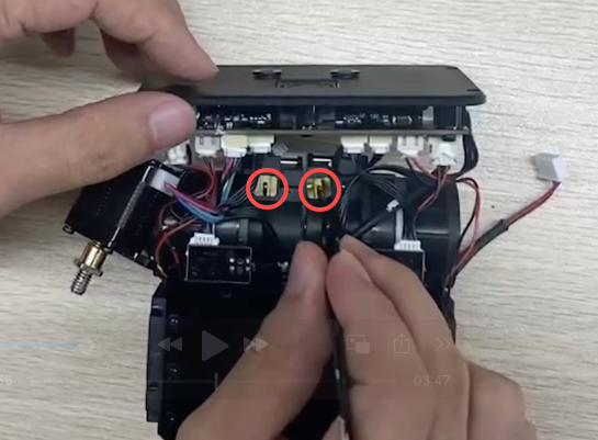
The opening of the copper block should face downwards.
-
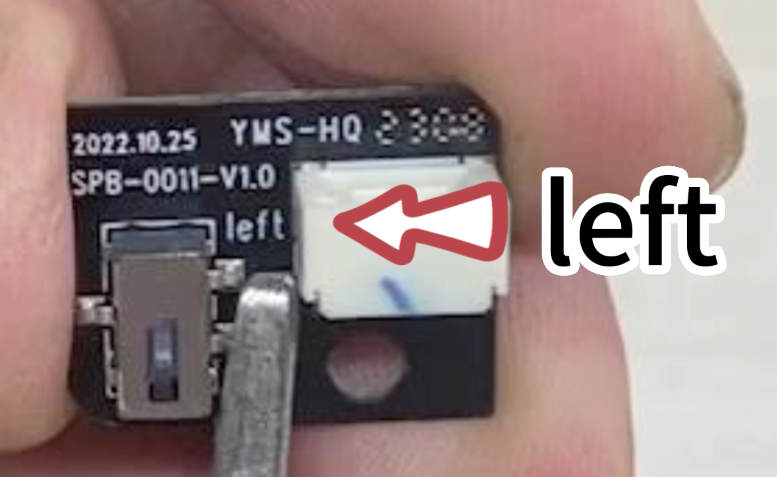
Take out and differentiate the right and the left filament runout sensor.
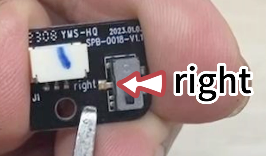
-
Place the plastic spacer column, then place the correct sensor on top of it.
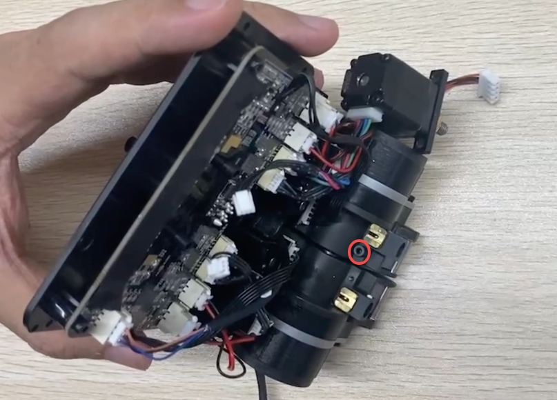
-
Reinstall the securing screw, yet do not fully tighten it.
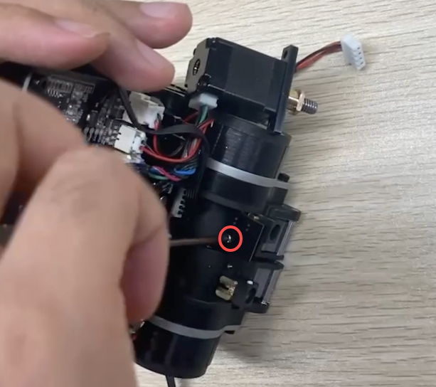
You can insert a segment of filament to check whether the sensor screws are properly tightened. If the filament cannot be pulled up and down, the screws need to be loosened accordingly.
-
Repeat the above steps on the other side.
-
Replug the cord of the filament runout sensor.
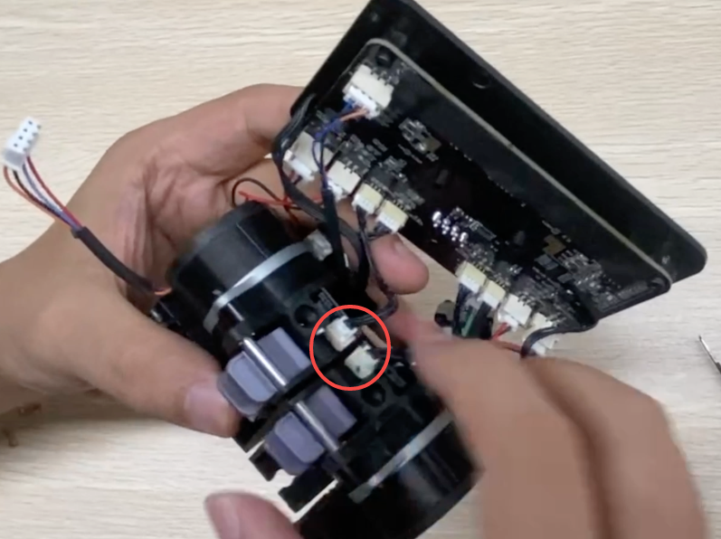
¶ Step 3. Restore the module.
- Refix the motor with the H2.0 screwdriver.
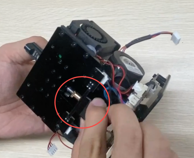
If the lead screw nut is outside the iron buckle, you need to push the right extruder inward and install the motor in place.
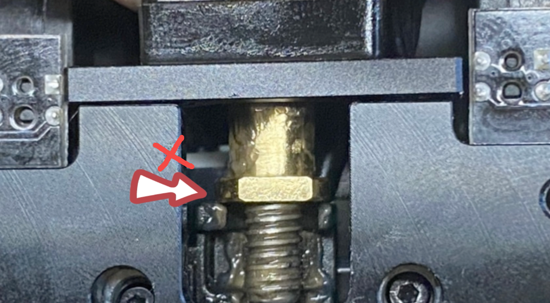
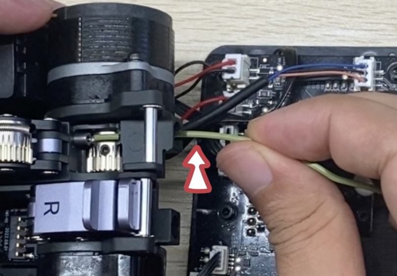
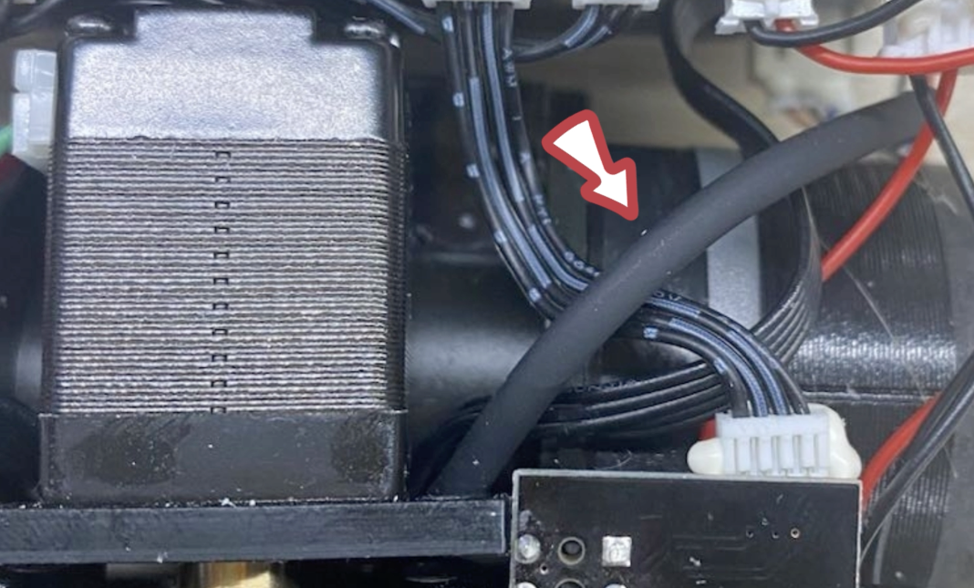
For the 2.0 Dual Extrusion Module, avoid clamping the proximity sensor cord when fixing the motor.
-
Replug the two motor cords.
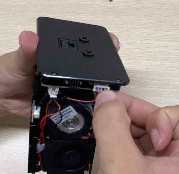
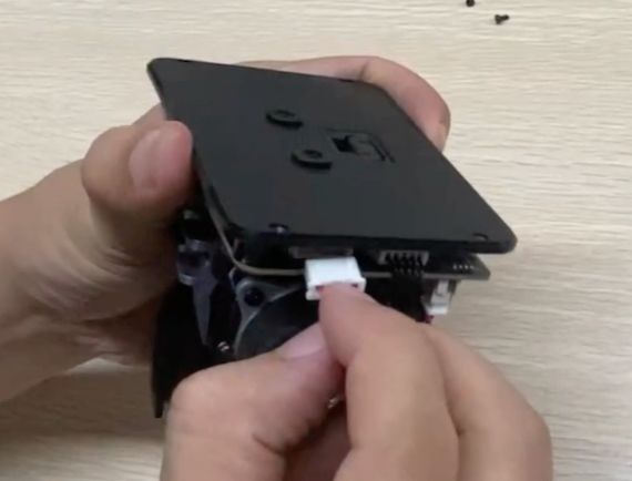
-
Now, all that's left is to install the shell and front cover. However, before proceeding, please follow these steps to test the functionality of the new filament runout sensor and check if the right extruder can lift normally:
- Turn off the machine and plug in the module. Then, turn on the machine.
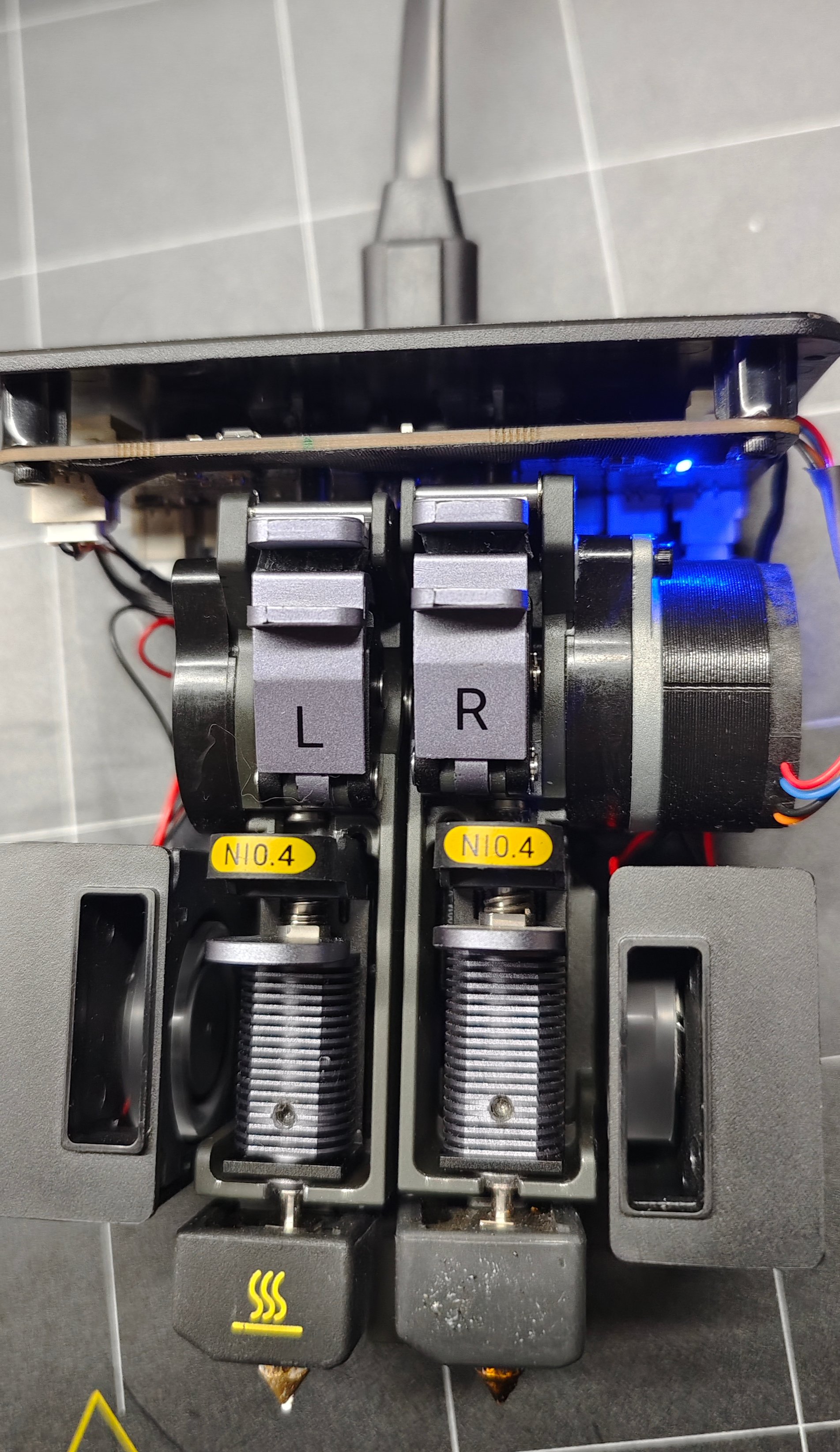
Exercise caution during the following procedure, and use a insulating glove if available.
The machine will initiate a homing procedure upon powering on, and during this process, the right extruder should lift up. If the right extruder fails to lift during homing, please verify the correct installation of the wire nut in Step 3.
- Insert a piece of filament into the extruder and observe if the red light on the control board illuminates. It should light up if the filament sensor is functioning properly. If not, inspect the installation of the trigger pads and copper blocks in Step 2. Repeat these checks for both the left and right filament runout sensors.
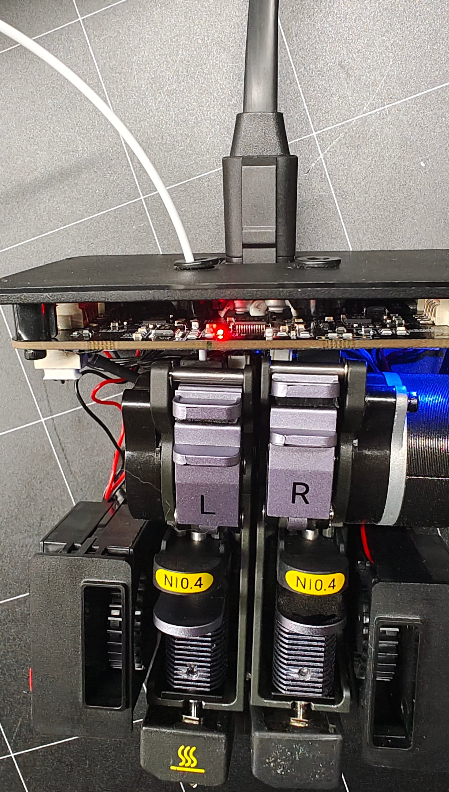
-
Attach the shell and the front cover, and use the H1.5 and H2.0 screwdriver to reinstall all the screws to the top and the back.
-
Attach the hot ends.
