Only when you use 1.6W/10W laser module, Camera Capture function will appear on top toolbar. 2W IR, 20W and 40W laser module do not support this function.
This feature takes effect when you connect Luban with the machine via Wi-Fi. If the connection is via the serial port, you will not be able to use this function.
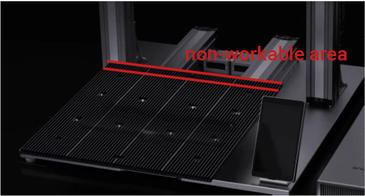
When you use Quick Swap Kit, the workable area of Y-aixs will reduce 15mm. When you use Bracing Kit, the workable area of Y-axis will reduce 12mm. Currently, Luban cannot detect the actual workable area when quick swap kit or bracing kit is installed. Be careful not to put your design in the non-workable area.
¶ Procedures
Before using the camera capture, please make sure that you have measured the focal length and calibrated the camera.
-
On Luban homepage, click Laser > 3-axis to enter the Laser G-code Generator.
-
Complete the Job Setup and click Confirm.
-
Drag the object file into Luban.
-
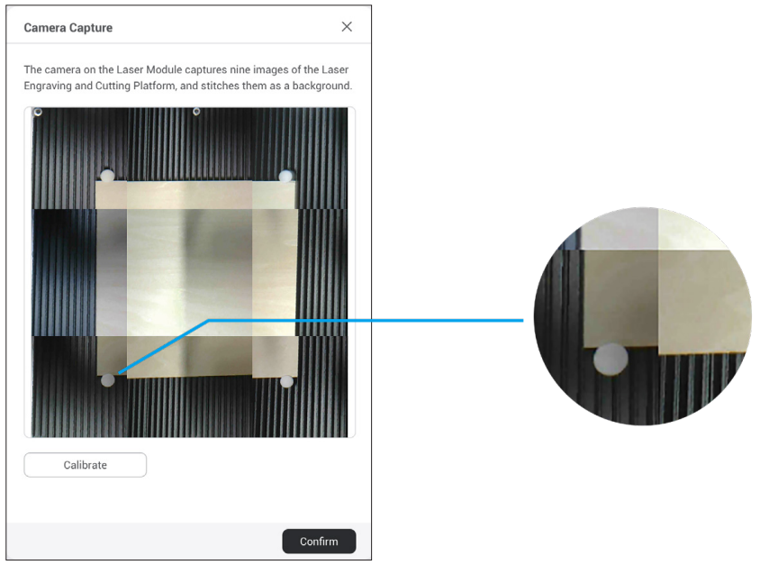
Go to the main toolbar and click Camera Capture > Add Background. Then click Start. Wait for the machine to take photos and stitch them into a panorama of the platform, then click Confirm.
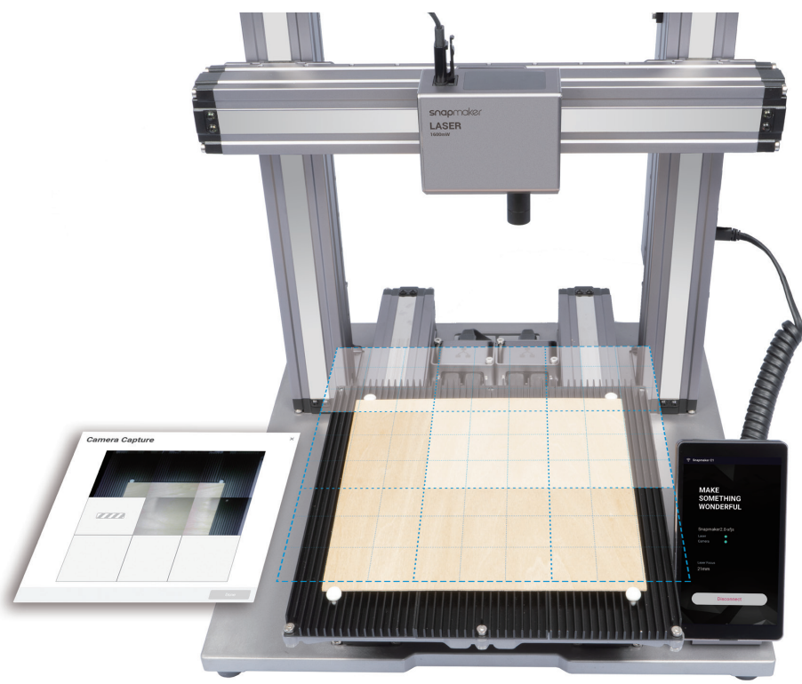
- If the edges of the captured image are not aligned, click Calibrate to manually calibrate the camera.
- Zoom into the image and move the lines until they perfectly match the square, then click Confirm -> Apply to see the finished image.
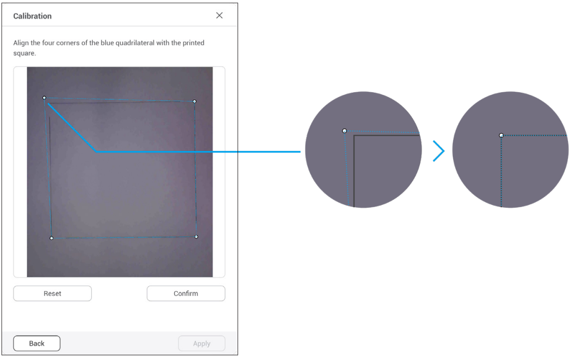
When calibrating the frame, align it with the engraved square(the blue square), not the background rectangle.
If there is only "Apply", but no "Confirm" button in the interface, it might be due to your computer's resolution. You can try adjusting the resolution.
- Click Confirm, and the finished image will be loaded in the coordinate system. You can repeat the steps above if the edges of the captured image are still not aligned.
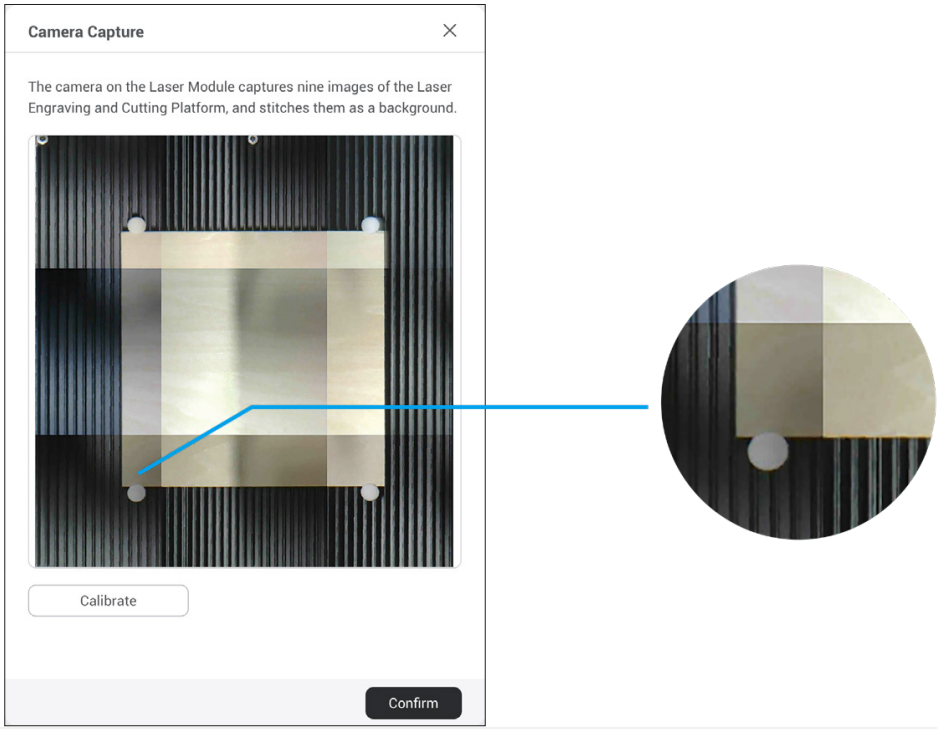
-
Drag the image to where the cutting will take place on the captured platform.
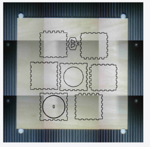
-
Edit the object if needed, then click Next.
-
Click Process > Create Toolpath, click Save when finished.
-
Click Generate G-code file to preview the toolpath.
Before using the camera capture, please make sure that you have finished toolhead focus calibration, thickness measurement system calibration and camera calibration.
-
On Luban homepage, click Laser > 3-axis to enter the Laser G-code Generator.
-
Complete the Job Setup and click Confirm.
-
Drag the object file into Luban.
-
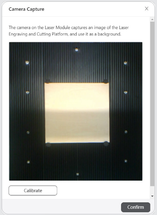
In the menu bar, click Camera Capture > Add Background > Normal Mode > Start. The machine will take a photo of the work area and use it as the background for the object to be engraved or cut. After the photo is captured, click Confirm.
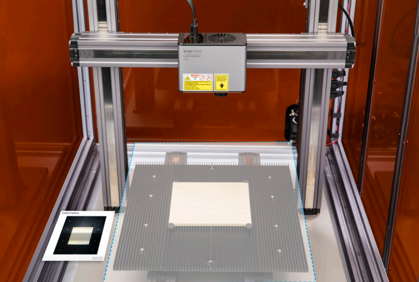
For 10W laser module, Luban supports two ways for camera capture: Normal Mode and Thickness Compensation Mode. Normal Mode is suitable for thinner workpieces < 2mm, while Thickness Compensation Mode is suitable for thicker workpieces (> 2mm), but can also achieve precise results on thinner workpieces. Depending on the material's thickness and transparency, this mode may not be able to adjust large workpieces properly.
If the captured image is twisted out of shape, click Calibrate to manually calibrate the camera.
①Zoom into the image and move the lines until they perfectly match the square, and then click Confirm > Apply to see the finished image. If the object in the photo remains twisted, click Calibrate and repeat this step.
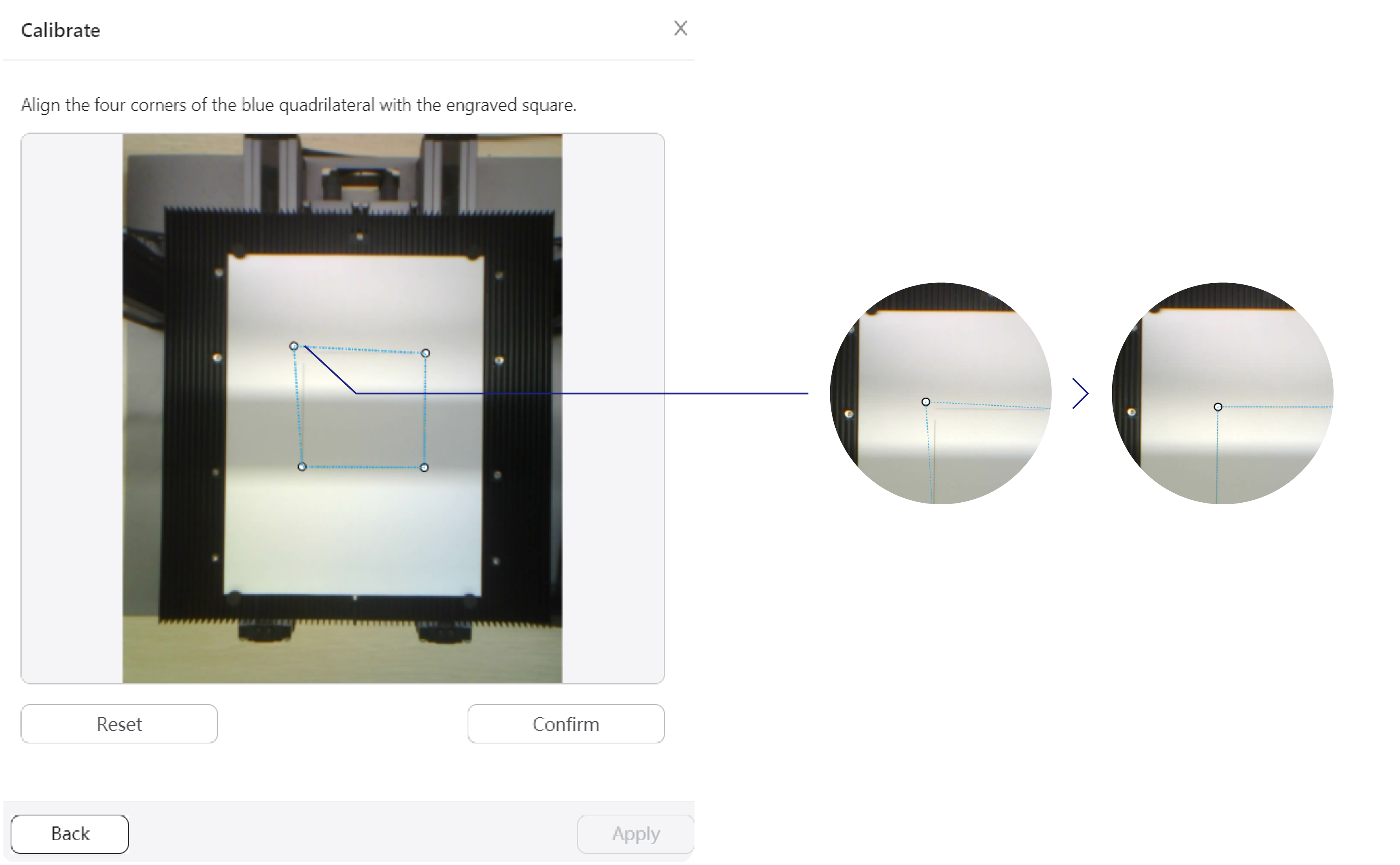
When calibrating the frame, align it with the engraved square(the blue square), not the background rectangle.
If there is only "Apply", but no "Confirm" button in the interface, it might be due to your computer's resolution. You can try adjusting the resolution.
②After you obtain a normal-shaped image, click Confirm. The finished image will be loaded in the coordinate system.
-
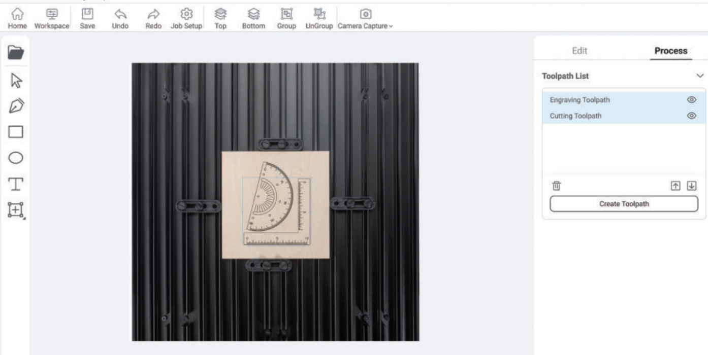
With the captured image as the background, press Ctrl + A on the keyboard to select all the objects on the canvas and drag them to the area where you want to laser engrave and cut.
-
Click Create Toolpath, use Luban's default settings and click Save.
-
Click Generate G-code file to preview the toolpath.
